
Abstract
It is well known from Maxwell theory that electromagnetic radiation is emitted whenever electric charges are accelerated in free space. This radiation assumes quite extraordinary properties whenever the charged particles move at ultrarelativistic speed: The radiation becomes very powerful and tightly collimated in space, and it may easily cover a rather wide spectrum ranging from the THz into the hard X-ray regime. When generation of such radiation is intended rather than being a side effect, the charged particles are normally electrons, thus kinetic energies are then typically in the multi-MeV range.
You have full access to this open access chapter, Download chapter PDF
11.1 Synchrotron Radiation and Free-Electron Lasers
11.1.1 Synchrotron Radiation
11.1.1.1 Basic Properties of Synchrotron Radiation
It is well known from Maxwell theory that electromagnetic radiation is emitted whenever electric charges are accelerated in free space. This radiation assumes quite extraordinary properties whenever the charged particles move at ultrarelativistic speed: The radiation becomes very powerful and tightly collimated in space, and it may easily cover a rather wide spectrum ranging from the THz into the hard X-ray regime. When generation of such radiation is intended rather than being a side effect, the charged particles are normally electrons, thus kinetic energies are then typically in the multi-MeV range.
The theoretical treatment of synchrotron radiation starts traditionally from retarded Lienard-Wiechert potentials [1], allowing quantitative determination of radiation properties in detail:
Here, q is the accelerated point charge, ε 0 is the dielectric constant, and \( \overrightarrow{R} \) is the distance vector from the charge to the observer, with the unit vector \( \overrightarrow{n}=\overrightarrow{R}/R \) and \( \overrightarrow{\beta}=\overrightarrow{v}/c \) the particle’s velocity \( \overrightarrow{v} \) normalized to the vacuum speed of light c, see Fig. 11.1. For simplicity, and without loss of generality, we assume the observer is located at the origin at R = 0.

Geometry of actual and retarded position of moving particle, and position of observer
All quantities in Eq. (11.1) must be taken at the retarded time t′ = t − R/c, i.e. not at the time t of observation but at the time when a signal moving at speed c must be emitted from the charge’s position in order to reach the observer at time t. This latter fact is actually the origin for many peculiarities of synchrotron radiation.
The electric and magnetic fields are derived from Eq. (11.1) using γ 2 = 1/(1 − β 2), \( \overrightarrow{E}=-\nabla \phi -\partial \overrightarrow{A}/\partial t \) and \( \overrightarrow{B}=\nabla \times \overrightarrow{A} \):
and
While Eqs. (11.2) and (11.3) are well suited to calculate quantitatively the field of a charge moving on a well-known path, some general properties of the field are more conveniently determined from the equivalent expression Eq. (11.4) given in [2]:
The first term describes the static Coulomb field, scaling with R −2. The second term modifies the field direction of the Coulomb field such that, in case of a charge moving at constant speed, the Coulomb field is NOT directed towards the retarded position of the particle (as it might be suggested by the first term) but rather to the instantaneous position of the charge just at the time t of observation. This will be shown below.
All radiation is described by the third term, and since it contains a contribution scaling with R −1, it is the dominant field at large distances from the source. Thus, in order to consider properties of synchrotron radiation qualitatively, it is sufficient to understand the behaviour of
Since the unit vector \( \overrightarrow{n} \) cannot change its length, one can see [2] that \( {d}^2\overrightarrow{n}/d{t}^2 \) is always perpendicular to \( \overrightarrow{n} \), i.e. to the retarded position of the particle if observed from a far distance. The fact that \( {\overrightarrow{E}}_{\mathrm{rad}}\left(0,t\right) \) is perpendicular to \( \overrightarrow{n} \) is also seen from the second term of Eq. (11.2) (describing the radiation in far zone) which would yield zero if scalar multiplied by \( \overrightarrow{n} \). Together with Eq. (11.3) it is seen that the Poynting vector \( \overrightarrow{S}=\left(\overrightarrow{E}\times \overrightarrow{B}\right)/{\mu}_0 \) is parallel to \( \overrightarrow{n} \). It is thus immediately clear that the radiation detected by the observer always seems to be originating from the retarded position of the particle, i.e. the retarded position is the apparent origin of the radiation, as it is intuitively expected when the speed of light is taken into account.
Equation (11.5) suggests that one just has to inspect the acceleration of the charge transverse to its apparent line of sight in order to understand the behaviour of the electric field component. For example, it is thus easily seen that radiation from an electron moving on a circular orbit is linearly polarized in the plane of the circle if the observer is located in the same plane. If, however, the radiation is observed from a position elevated out of this (say, horizontal) plane, one expects also a vertical field component.
Since Eqs. (11.2) and (11.4) look so differently, it is useful to sketch how Eq. (11.2) can be derived from Eq. (11.4): a key point is that Eq. (11.2) requires all derivations to be taken with respect to the retarded time t′ = t − R/c while Eq. (11.5) contains derivatives with respect to the time of observation t. Explicitly, this reads
From t′ = t − R/c it follows: dt′/dt = 1 − (dR(t)/cdt′)(dt′/dt). Solving for dt′/dt yields: dt′/dt = 1/(1 + dR/cdt′).
Due to \( \overrightarrow{n}\perp d\overrightarrow{n}/d{t}^{\prime } \) we get from Eq. (11.6): \( dR/ cd{t}^{\prime }=-\overrightarrow{n}\cdotp \overrightarrow{\beta} \) and thus
For ultrarelativistic motion, and in particular in forward direction \( \overrightarrow{n}\parallel \overrightarrow{\beta} \), dt' and dt differ by a really large factor
thus resulting in a huge compression of the time scale at which radiation properties are observed compared to the one at which electron motion takes place. It should be noted that this has nothing to do with any Lorentz transform but is rather a property of relativistic Doppler shift. The particle position at the retarded time is just a different point in space-time.
With Eq. (11.7) in mind, Eq. (11.4) can be rewritten (note we write (nβ) for \( \left(\overrightarrow{n}\cdotp \overrightarrow{\beta}\right) \) everywhere):
It is interesting noting that not only the last line but also all expressionsafter \( 3\overrightarrow{n}(n\beta)^3\) in the curly bracket stem from the “radiation term” \( \frac{1}{c^2}\frac{d^2}{d{t}^2}\overrightarrow{n} \).
After expanding \( \overrightarrow{n} \) by \( \frac{{\left[1-\left( n\beta \right)\right]}^3}{{\left[1-\left( n\beta \right)\right]}^3} \), the curly bracket in Eq. (11.9) can be simplified into \( \left\{\ \right\}=\frac{1}{{\left[1-\left( n\beta \right)\right]}^3}\frac{\overrightarrow{n}-\overrightarrow{\beta}}{\gamma^2} \), completing the proof that Eqs. (11.2) and (11.4) are equivalent.
In the following, we will restrict ourselves to properties of the radiation field \( {\overrightarrow{E}}_{\mathrm{rad}} \) described by the second term in Eq. (11.2) or by Eq. (11.5), which are equivalent if the observation is made at sufficiently large distance R from the charge (“far-zone approximation”), since in this case the contribution from the curly bracket in Eq. (11.9) to Eq. (11.5) can be neglected:
It should be emphasised that there are indeed practical cases where this approximation is not valid, e.g. if radiation from an undulator (see below) of length L u is observed from a distance not much larger than L u [3].
In most experimental cases the time evolution of the electric field vector is not observable but only the radiation power and its angular or spectral distribution.
In discussing properties of synchrotron radiation it is important to distinguish the instantaneously emitted power (and its angular distribution) from the time development of the power observed by an experimentalist fixed in the lab system. While the first is described in terms of the retarded time t', the latter is observed on the time scale t, which makes a big difference for ultrarelativistic motion, see Eq. (11.7). We point out again that this has nothing to do with a Lorentz transform.
Radiation Power and Its Angular Distribution
The radiation power density is described by the Poynting vector \( \overrightarrow{S}=\left(\overrightarrow{E}\times \overrightarrow{B}\right)/{\mu}_0={\varepsilon}_0c{\left({\overrightarrow{E}}_{\mathrm{rad}}\right)}^2\overrightarrow{n} \) , where \( {\overrightarrow{E}}_{\mathrm{rad}} \) is the far zone radiation field given in observer time t according to Eq. (11.10). In the present section, we want to refer the radiation power P in far zone to the motion of the electron (i.e. to an emission time interval dt'), so we need to consider
where dΩ is the solid angle element into which the power is emitted. Thus,
This is the most general expression for the angular dependence of the energy loss into radiation of an accelerated point charge in far-field approximation.
There are essentially two different acceleration mechanisms which need to be distinguished: Acceleration \( {\dot{v}}_{\perp } \) perpendicular to the direction of motion, usually provided by a magnetic field B ext, and acceleration \( {\dot{v}}_{\parallel } \) by an electric field E ext parallel to the momentarily velocity.
The total radiation power due to \( {\dot{v}}_{\perp } \) can be shown to be
Here, \( \varrho =\left|\overrightarrow{p}\right|/\left(q{B}_{\mathrm{ext}}\right) \) is the bending radius of the particle with momentum \( \overrightarrow{p} \) and charge q in presence of a magnetic field B ext directed perpendicular to \( \overrightarrow{p} \).
The total radiation power due to \( {\dot{v}}_{\parallel } \) is, on the other hand,
with dγ/ds the acceleration due to the longitudinal electric field. In almost all practical cases this radiation power is much smaller than the one generated in a magnetic field of 1 T.
Thus, for the remainder of this paper, we restrict ourselves to acceleration due to magnetic fields.
For circular accelerators the total energy loss U rad during one turn of the charged particle due to synchrotron radiation is an important quantity. From Eq. (11.13) one calculates
where the integral extends over all bending magnets. The last expression represents the radiation loss in practical units in the case of electrons or positrons, with E 0 the particle energy. For simplicity is has been assumed that ρ is constant in all bending magnets.
According to the γ 4-scaling of Eqs. (11.13) and (11.15), synchrotron radiation constitutes a massive challenge on the construction of electron/positron synchrotrons in the multi-GeV range. As an extreme example, in the electron-positron storage ring LEP at CERN each particle lost approximately U rad = 2850 MeV per turn when running at its maximum particle energy of E 0 = 100 GeV, even though the bending radius was as large as ρ = 3100 m.
On the contrary, emission of synchrotron radiation is a negligible effect for hadrons in most practical cases.
In a magnetic field, the acceleration is always perpendicular to the velocity: \( \dot{\overrightarrow{\beta}}\perp \overrightarrow{\beta} \). Then, Eq. (11.12) can be expressed in more practical units, reflecting the geometry illustrated in Fig. 11.2:

Geometry and definition of parameters used in Eq. (11.16)
The direction of observation \( \overrightarrow{n} \) is expressed here in terms of the angles φ,θ as illustrated in Fig. 11.2.
For ultrarelativistic particles, i.e. if 1 − β ≪ 1, the denominators 1 − β cos θ get very small around θ ≈ 0 such that the radiation is concentrated very much in the direction of \( \overrightarrow{\beta} \).
Figure 11.3 illustrates the directivity of synchrotron radiation according to Eq. (11.16) for two different particle energies.

Synchrotron radiation emitted by an ultrarelativistic charged particle is concentrated into a narrow cone with opening angle 1/γ
It should be pointed out that the directivity of synchrotron radiation described by Eq. (11.16) is an instantaneous property of emission, thus is depends only on the local magnetic field strength in the very moment of emission. An observer located in far distance may in fact observe field contributions stemming from several sections of the electron’s trajectory. This will be discussed later.
For γ ≫ 1 and θ ≪ 1 we get 1 − β cos θ ≈ (1 + γ 2 θ 2)/(2γ 2) and thus:
Equation (11.17) illustrates even more that the emission is concentrated into a cone of opening angle θ ≈ 1/γ with respect to the forward direction. A rigorous calculation shows that the rms-opening angle is indeed exactly 1/γ [4].
For practical calculations it might be useful to replace \( \left|\dot{\overrightarrow{\beta}}\right| \) by β 2 c/ρ ≈ c/ρ with 1/ρ = qB/p 0 describing the bending radius ϱ.
An observer in far distance sees a radiation field only during the short time when the cone passes the observer’s aperture, see Fig. 11.4.

Scenario of synchrotron radiation detection by a distant observer
For an observer in the plane of deflection, the radiation field has only a non-zero component E x(t) in this plane, as can be understood easily from Eq. (11.5). It is thus linearly polarized. Due to the strong retardation effect described by Eq. (11.7), this time duration is indeed much smaller than the time ∆t′ ≈ (2/γ)(ρ/c) the electron needs to cover an angle of 2/γ on its curved trajectory, namely shorter by a factor 2γ 2. Thus one expects a radiation pulse duration ∆t ≈ (2ρ)/(cγ 3). More precisely, the time profile (in the plane of deflection) is illustrated in Fig. 11.5 [4]. It consists essentially of a single spike with a characteristic duration 1/ω c. The “critical frequency” ω c is defined by

Time profile of radiation field experienced by a distant observer
11.1.1.2 Spectrum of Synchrotron Radiation from a Long Bending Magnet
In most practical cases, a user of synchrotron radiation is interested in the spectral properties rather than in time domain features. Since the user refers to radiation properties at the location of the observer, we have to investigate the expression
instead of Eq. (11.11). P(t) = ∆W/∆t describes the amount of energy ∆W radiated within the observer’s time interval ∆t. The total energy radiated per passage into the solid angle dΩ is thus
With the help of Parseval’s theorem, the r.h.s. of Eq. (11.20) can be turned into frequency domain: \( \underset{-\infty }{\overset{\infty }{\int }}{\left|\overrightarrow{E}(t)\right|}^2 d t=\underset{-\infty }{\overset{\infty }{\int }}{\left|\overrightarrow{E}\left(\omega \right)\right|}^2 d\omega \). Here, the Fourier transform of the electric field \( \overrightarrow{E}(t) \) is used:
The energy radiated into the solid angle dΩ and frequency interval dω is thus given, in far field approximation, by
The factor of 2 appears since \( \overrightarrow{E}(t) \) is a real quantity, such that negative frequencies are not considered. According to Eq. (11.10), this means that the expression
needs to be evaluated. The term (t − R/c) appears in the exponent since all quantities \( \overrightarrow{n} \), \( \overrightarrow{\beta} \), \( \dot{\overrightarrow{\beta}} \), R must be evaluated at the retarded time. It should be noted that, in order the solid angle dΩ to be well defined in Eq. (11.20), the relevant part of the trajectory should remain for all times within a volume of diameter much smaller than R, e.g. in a circular accelerator.
For motion on a circle in a constant magnetic field, the result reads [1]:
with the abbreviation
\( {K}_{2/3}^2 \) and \( {K}_{1/3}^2 \) are Bessel functions of fractional order.
Equation (11.24) is of course not any more an instantaneous property but refers to the average over the entire passage of the electron. The angle θ describes the elevation of the observer with respect to that tangent to the circle of motion where \( \overrightarrow{n}\cdotp \overrightarrow{\beta} \) becomes maximum in Fig. 11.2 (corresponding to φ = 90°).
It should also be noted that, although the integral in Eq. (11.23) extends from minus to plus infinity, it does not consider the fact that the electron (normally) performs multiple revolutions in the synchrotron, such that the radiation cone passes the observer many times per second. This fact can be accounted for by multiplying Eq. (11.23) by the revolution frequency which would turn the radiated energy per passage into an average radiation power, and the spectrum would become a discrete one.
The term with K 2/3 describes the radiation polarized in the (horizontal) plane of deflection (σ-polarization), while the K 1/3 contribution is vertically polarized (π-polarization). As mentioned before and inferred from Eq. (11.5), the π-polarization has no intensity in the plane of deflection (θ = 0), while the horizontal polarization has its maximum there. Both components have a rather broad spectral distribution with a maximum close to ω c.
According to Eq. (11.25), the functional dependence of d 2 W/(dΩdω) on ω and θ is a universal one if these quantities are normalized to ω c and 1/γ, respectively. Using such normalized variables, the frequency and angular dependence of the polarization components are illustrated separately in Fig. 11.6. The vertical opening angle decreases with rising frequency and is about ±1/γ around ω = ω c.

σ-polarization (left) and π-polarization (right) component of synchrotron radiation from a bending magnet. The axis to the left describes the frequency normalized to the critical frequency ω c, while in the plane perpendicular to ω/ω c, the directivity of intensity is depicted, with the angle θ taken in normalized γθ units. The intensity is in arbitrary units
Since in most practical cases γ is very big and the opening angle is thus very small, the angular dependence is often not resolved by users. Integration of Eq. (11.24) over the vertical angle θ yields the spectral power density
Equation (11.26) summarizes both polarization components. Again, if the frequency is normalized to ω c, the spectral power density can be expressed by the universal function
see Fig. 11.7 (note that, in contrast to Fig. 11.6, a double logarithmic scale is used). For a discussion of the individual σ- and π-components see, for instance, [4].

Normalized power spectrum see Eq. (11.27) (solid line) and photon number spectrum (broken line) of synchrotron radiation
Photon Distribution
Sometimes it is necessary to pay attention to the fact that synchrotron radiation is emitted, as any electromagnetic radiation, in quanta (photons) of energy ε γ = ℏω, where ℏ is Planck’s constant. The spectral angular photon flux can be obtained from Eq. (11.24), dividing by ℏ:
Equation (11.28) calculates the number of photons N γ emitted per unit solid angle into a relative photon energy interval dε γ/ε γ. Again it is noted that this quantity refers to a single turn in the synchrotron.
The angular-integrated spectral photon spectrum corresponding to Eq. (11.26) can be expressed in the form
with the fine structure constant α = 1/137.036. This spectrum is also depicted in Fig. 11.7.
Integrating Eq. (11.29) over all frequencies yields the total number N γ of photons emitted per electron per turn in the synchrotron:
It is interesting to note that N γ is typically about 100, i.e. it is a rather small number, although the photon number spectrum diverges for ω → 0, see Eq. (11.29) and Fig. 11.7.
The mean photon energy is given by
The considerable granularity in the emission process has quite some impact on the electron beam parameters in electron storage rings [5].
11.1.1.3 Simple Means of Changing the Emission Spectrum
Users often don’t appreciate the spectrum of synchrotron radiation, either because of its large frequency width or because it might not contain sufficiently high frequencies for the particular application. In the latter case, the most straight forward solution would be making use of the strong γ-dependence of Eqs. (11.24) and (11.26) and increasing the electron energy. However, there are often considerable technical limitations in this respect, in particular at electron storage rings operating in the GeV regime.
Wavelength Shifters
As the synchrotron radiation spectrum is normalized to the critical frequency ω c, according to Eq. (11.18) the spectrum can also be hardened by increasing the magnetic field strength, thus reducing the bending radius ρ. To this end, often superconducting magnets are applied. In order to restrict the subsequent modification of the electron beam’s design orbit to a small section of the storage ring, a sequence of dipole magnets is frequently used with zero net deflection angle. Such an arrangement is called wavelength shifter. The radiation properties are determined in the same way as for ordinary synchrotron radiation. Beyond hardening the spectrum and increasing the flux, there is also some advantage in terms of flexibility in the geometrical arrangement of radiation beam lines.
Short-Magnet Radiation, Edge Radiation
When discussing the characteristic time profile of synchrotron radiation it was assumed in the context of Figs. 11.4 and 11.5 that the electron would propagate in the magnetic field for sufficiently long time such that the radiation cone passes the observer’s aperture in its entire angular extension of ±1/γ. To this end, the dipole magnet must have a length of at least
For electrons and magnetic fields in the B ≈ 1 T range, this results in a few millimeters, which would be of little relevance in most cases. However, if B is much weaker, or if protons are considered (e.g. at LHC/CERN), the resulting time profile of the radiation field is shorter than shown in Fig. 11.5 and assumed for the calculation of the synchrotron radiation spectrum. As the time profile gets shorter, its Fourier transform extends to higher frequencies, thus the spectrum gets “harder”. In contrast to increasing B or γ, this hardening is, however, not accompanied by increased flux as the instantaneous properties of emission depend only on the local magnetic field strength which does not change by shortening the magnet.
A spectrum hardening effect similar to short-magnet radiation takes place if the magnetic field rises at the entry face of the magnet (or drops at the exit, respectively) over a distance comparable to or smaller than given by Eq. (11.32). In such case, the time profile of the radiation field exhibits a rising (or falling, respectively) edge steeper than that seen in Fig. 11.5. As a consequence, the Fourier transform extends to rather high frequencies. At high-energy proton synchrotrons this is being used to extend the spectrum towards wavelengths which are easy to observe.
11.1.1.4 Wigglers and Undulators
Definitions
Undulators and wigglers provide a periodic magnetic field over a part of the synchrotron’s circumference. In most cases, the magnetic field perpendicular to the electron beam’s design orbit can be described by a pure sinusoidal—at least within the small spatial area where the electron beam is present. If the field acting on the electron beam has only one non-zero Cartesian component, the device is called a planar undulator (or wiggler, respectively). The field close to the axis can then be described by
Here, B 0 is the field amplitude and k u = 2π/λ u is the undulator wave number, with λ u the undulator’s period. The z-axis is along the electron beam’s initial design momentum, and we have chosen arbitrarily the magnetic field to be in the vertical y-direction.
Typically, the length L u of these devices is a few meters, and the field integral
is made zero such that there is no over-all deflection of the electron beam’s trajectory.
A key parameter is the undulator parameter
As this quantity refers to electrons (or positrons), we have assumed m 0 to be the electron rest mass m e in the last part of the equation. A device with K ≤ 1 is called undulator, while wigglers exhibit values K > 1. Sometimes devices with K > 1 are also called undulators if they are used in terms of radiation properties typical of undulators, e.g. when observing the line spectrum in forward direction (see below).
Undulators and wigglers are realized in basically three varieties of technology: iron-based electromagnets, permanent magnets and superconducting magnets. For details, see e.g. [6].
Particle Trajectory
The equation of motion of an electron (with elementary charge −e) moving in presence of the field of Eq. (11.33) reads in Cartesian components
To first-order approximation, the periodic solution reads
This motion is illustrated in Fig. 11.8.

Periodic electron motion (red) in a planar undulator fabricated in hybrid permanent magnet technology. The magnet field is indicated by green arrows
It should be noted that, in order this periodic trajectory to happen, the electron beam must enter the device on an orbit representing the appropriate initial conditions. In addition, the undulator field must begin and end with a quarter-period undulator section.
From Eq. (11.37) the maximum deflection angle can be calculated:
The maximum orbit excursion of the electron is
Under many typical conditions, this results in only a few micrometers and is thus much smaller than the typical electron beam diameter.
In Eq. (11.37) the longitudinal motion z(t)was described only to first order, not taking into account its coupling to the transverse motion. A more precise, second order calculation results in
where the abbreviation \( {\omega}_u=\overline{\beta}c{k}_u \) and the average longitudinal velocity
have been introduced. According to Eq. (11.40), the oscillatory motion in the transverse plane translates into a small modulation of the longitudinal velocity around \( {\overline{v}}_z \). This average longitudinal velocity differs, as described by Eq. (11.41), from c due to two effects: the factor 1 − 1/(2γ 2) ≈ β describes by how much the electron’s total speed differs from c. The factor 1 + K 2/2 describes the mean additional longitudinal retardation due to the transverse velocity components.
Radiation Properties
Calculation of the radiation spectrum starts again from Eqs. (11.22) and (11.23), however, now the oscillatory motion in the undulator field must be considered when evaluating Eq. (11.23). Qualitatively, it should be clear from Figs. 11.4 and 11.9 that the time profile of the wiggler radiation field (K > 1) should resemble the standard dipole field case with the only difference that there will be a series of radiation spikes, see Fig. 11.10. The radiation spectrum differs thus not very much from the synchrotron radiation case but will be N times more intense with N being the number of wiggler periods (see Fig. 11.11).

Emission of radiation cones along the oscillatory trajectory in an undulator or wiggler. In this schematic, the wiggler case K > 1 is illustrated, where the deflection angles ϑ = K/γ are larger than 1/γ

Time profile of radiation field for wiggler (solid line) and undulator radiation (broken line). Note that these two time profiles do not belong to the same undulator period, although they have obviously the same fundamental period in time. The reason is that the slippage between the longitudinal electron velocity and c is larger in the wiggler than in the undulator case

Undulator spectrum in forward direction for γ = 1000 and N = 10 undulator periods. The undulator parameter is K = 0.5 (top) and K = 2 (bottom). The undulator period is λ u = 2 cm. The vertical scales are in arbitrary units. The broken line in the lower diagram shows the spectrum of synchrotron radiation for a magnetic dipole field equal to the peak field of the undulator, with the vertical scale matched to the undulator spectrum arbitrarily
On the contrary, in the undulator case K ≤ 1, an observer will only see radiation field within a small angle of approximately ±1/γ with respect to the forward direction, and within this angle he will observe a continuous oscillatory field with N periods. Fourier transform of this time profile results in a fundamental wavelength
and higher harmonics λ k = λ 1/k. From symmetry consideration one can immediately understand that in forward direction θ = 0 there will be only odd harmonics.
The angular spectral energy distribution in forward direction (see Fig. 11.11) is given by [4]
The sinc-function with argument πN(ω − kω 1)/ω 1 describes the spectral distribution of the individual undulator harmonics. The total line width of harmonics k is
The photon number spectrum radiated into the frequency interval Δω/ω k in forward direction is given by
α is again the fine structure constant.
As compared to the synchrotron radiation spectrum Eq. (11.24), undulator radiation provides a spectral density in forward direction larger by some factor N 2. One factor N results from having a number of N undulator periods. The other factor N stems from the fact that, due to interference, the radiation spectrum is concentrated into narrow resonance lines. Thus, in forward direction, the field amplitudes add up coherently, not the intensities. The total radiation energy increases with N as expected.
Sometimes, e.g. for spectroscopy applications, only the spectral contribution of the undulator harmonics in forward direction is of interest. This radiation has a very narrow opening angle:
It is some factor of \( 1/\sqrt{kN} \) narrower than with synchrotron radiation.
Helical Undulators
A helical undulator generates a magnetic field vector following a helical orientation like
The resulting electron orbit is (appropriate initial conditions given) also a helix, with velocity components
which are both constant.
The major differences compared to planar undulators are:
-
(i)
For calculation of the fundamental wavelength according to Eq. (11.42) one needs to replace K 2/2 by K 2.
-
(ii)
According to Eq. (11.5), the electric field vector of undulator radiation in forward direction will also move on a perfect helix, thus this radiation will be circular polarized, and it will consist of only the fundamental harmonics, independent of the magnitude of K.
11.1.1.5 Radiation from Many Electrons
Brilliance
The emittance of a synchrotron radiation photon beam, i.e. the product of rms opening angle \( {\sigma}_{\gamma}^{\prime } \) and rms source size σ γ is limited due to diffraction. For a perfect Gaussian optical mode, the minimum-emittance is achieved, given by [4, 7]
with the wavelength of radiation λ.
As the emittance of the photon beam can never be smaller than indicated by Eq. (11.49), the very narrow opening angle of undulator radiation, Eq. (11.46), means that photons radiated from an undulator have a rather large apparent source size.
If a radiating electron beam has an emittance ε e smaller than given by Eq. (11.49), the resulting radiation will be indistinguishable from radiation of a point source, if the opening angle \( {\sigma}_e^{\prime } \) of the electron beam is matched to the opening angle of the radiation. A crude estimate for \( {\sigma}_e^{\prime } \) is \( {\sigma}_e^{\prime}\approx \sqrt{\varepsilon_e/\beta } \), where β is the magnet optics beta function. Thus, a comparison with Eq. (11.46) would result in an estimated matched beta function ≈L u/4π. However, such a small value cannot be kept constant within the undulator length if there are no further magnetic focusing elements. A more appropriate value is thus somewhat larger [4]:
It should be noted that these considerations apply for both transverse directions x/y independently.
An electron storage ring providing an electron emittance
in both x and y is said to work at the diffraction limit. Designing electron storage rings operating at (or close to) the diffraction limit is a difficult task, in particular if the wavelengths of interest are very short, e.g. in the hard X-ray regime. In tendency, this requires large ring diameters and sophisticated electron beam optics arrangements. Quite some efforts in this direction are under way at several big laboratories at the time of writing the present article.
In practice, Eq. (11.51) can often not be fulfilled. In this case, since both the photon and electron distributions are Gaussian in good approximation, the effective, combined distribution is given by a convolution and results in
This holds for both, transverse dimensions and opening angles, and applies again for both transverse directions x/y independently.
Many experiments using synchrotron (or undulator) radiation rely on the possibility to focus a small spectral fraction ∆ω/ω of the photon beam, selected e.g. by a monochromator, onto a small spot at the experiment. The figure of merit for such experiments is the brilliance B:
This quantity is also called brightness by some authors. dn/dt is the number of photons per unit time, and Σ x, etc., are the rms photon beam extensions in x,y dimensions, convoluted in the spirit of Eq. (11.52).
In RF accelerators, electrons are arranged within bunches such that the peak beam current is much larger than the average current. Thus, the instantaneous value of brilliance during the very moment of bunch passage is much larger that its time average.
Undulator beam lines at modern storage rings reach peak brilliance values up to B peak ≈ 1025 mm−2 mrad−2 s−1 (0.1%)−1, see Fig. 11.12.

Peak brilliance values delivered by typical undulator beamlines at some state-of-the-art synchrotron radiation storage rings. Values for FEL facilities are also shown. It should be noted that some of the FEL facilities (FLASH, European XFEL) are driven by a superconducting linear accelerator providing an electron bunch repetition rate larger by several orders of magnitude than normal conducting ones, resulting in a correspondingly larger rate of photon pulses. This difference is not visible in this figure of peak values but may be beneficial for several scientific applications
Average brilliance values can exceed values B avg ≈ 1021 mm−2 mrad−2 s−1 (0.1%)−1.
In case of a perfectly diffraction limited beam in both x/y directions, it is concluded from Eqs. (11.49), (11.51), and (11.52) that Eq. (11.53) simplifies to:
Coherent Synchrotron Radiation
In sections “Basic Properties of Synchrotron Radiation” through “Wigglers and Undulators”, emission by a point charge has been considered. In this case, the intensity scales with the radiating charge q squared. In other words, if this quasi-point charge consists of N e electrons, the total power would be \( {N}_e^2 \) larger than the power P 0 radiated by a single electron.
In general, if radiation of many electrons is considered, we need to add up first the electric field vectors \( {\overrightarrow{E}}_k \) of all electrons coherently before calculating the intensity. In the following we restrict ourselves to the one-dimensional case, where all electrons follow the same path, but just at different times (“pencil beam”). In most cases, the transverse extension of the bunch does not alter the results significantly.
In case of a pencil beam, the electric field contributed by any of the electrons differs from the field of the others only in terms of the phase factor exp{iω(t − R k/c)} in Eq. (11.23), since, at time t, the electron with index k is located at a retarded distance R k while others will be located at a different distance. Calling these individual phases differences φ k, the power radiated by the ensemble scales like
How much of phase difference is introduced by a difference in longitudinal position z k depends, of course, on the wavelength λ considered:
If the longitudinal positions of electrons are random, the last term in Eq. (11.55) cancels and the resulting power is given by
with P 0 the power of a single electron. This contribution is called incoherent radiation.
If, however, the charge distribution is non-random, we describe the longitudinal charge distribution by a normalized density function ρ(z). This function determines, when evaluating the double sum of phase factors in Eq. (11.55), how often each phase difference value appears, so the double sum can be translated into a Fourier transform of ρ(z). The expectation value of the power radiated by the ensemble is then
Here,
is the longitudinal form factor of the charge distribution inside the electron bunch. The contribution
to the total radiation power is called coherent synchrotron (or undulator, respectively) radiation. Due to the large number N e of electrons in the bunch, P coh can exceed P inc by many orders of magnitude, even if the longitudinal charge profile has only a small Fourier content at the wavelength of interest.
At storage rings, where the charge distribution can be described very well by a Gaussian, with typical rms bunch length values of a few millimetres, P coh becomes noticeable only at wavelengths in the far infrared. On the other hand, emission of radiation is suppressed very effectively by shielding due to the vaccum chamber. This happens, if in the vacuum chamber, which can be regarded as a curved waveguide, is no propagating mode whose phase velocity matches with the particle velocity. A typical parameter is the shielding wavelength \( 2\pi\sqrt{h^3/R}\) that can be calculated for a flat chamber of height h and curvature radius R [8]. Thus, coherent synchrotron radiation is not observed at most storage rings, but it has been provoked by arranging the storage ring parameters to achieve very short bunches [9].
The dramatic increase of radiation power can also be achieved if the longitudinal charge density is modulated at the wavelength of interest. This is the physical basics of the free-electron laser (FEL).
At linear accelerators much shorter bunches can be realized than at storage rings, and longitudinal bunch profiles may exhibit a very rich internal structure at scales down to the micrometer range, in particular at high-gain FEL facilities, where bunch lengths in the few micrometer range are needed, see Sect. 11.1.2. At such accelerators, infrared spectroscopy of coherent synchrotron radiation (or of optical transition radiation) represents a powerful tool for electron beam diagnostics [10].
11.1.2 Free-Electron Lasers
11.1.2.1 One Dimensional FEL Theory
The interaction of electrons with electromagnetic waves in an undulator of an FEL is sketched in Fig. 11.8. Important aspects of the FEL process can be described in a model, where electromagnetic fields do not depend on the transverse coordinates x,y and the trajectories of particles with different transverse initial conditions are just transversely shifted. This does not exclude transverse motion of particles.
For the description of the interaction of electrons with waves we need only three types of state quantities. Two of them are particle coordinates in longitudinal phase space: the ponderomotive phase ψ, see below and the relative energy offset η. A third quantity \( {\hat{E}}_x \) stands for the complex amplitude of the electric field of the plane electromagnetic wave, and z, the length along the undulator axis, is the independent coordinate. To simplify the FEL equations, we are not interested in oscillations with the undulator period λ u, but in the variation of our quantities from period to period or in average versus one period. Therefore the FEL equations for a bunch with N particles (of index ν) per period are in principle of the following type
If the undulator parameters are z independent, and with some approximations they can be written as
The first equation relates the relative position in the bunch (ponderomotive phase) to the energy offset. This is just a linearized version of the equation of motion, that describes that a particle with more energy (higher η) is deflected less by the undulator, performs oscillations with smaller amplitude, has a shorter trajectory through one period and increases its phase (longitudinal position) relative to a particle without deviation from reference energy.
The second equation represents the change of particle energy caused by the electromagnetic wave. This depends on the phase of the particle ψ ν relative to the phase of the wave \( \arg \left({\hat{E}}_x\right) \) and on the absolute amplitude \( \left|{\hat{E}}_x\right| \). This clarifies the definition of the ponderomotive phase: ψ ν is Δz ν2π/λ l with Δz ν the length shift relative to a reference particle of reference energy (η ref = 0), and wavelength λ l into forward direction according to Eq. (11.42).
The third equation assumes that only one spectral line (usually the fundamental wavelength) is excited and is characterized by the amplitude \( {\hat{E}}_x \). This amplitude is driven by the microbunching of the particle distribution with the same wavelength. Therefore the Fourier coefficient of that wavelength, the bunching factor b, determines the increase of \( {\hat{E}}_x \). This approach of a resonant and slowly varying amplitude (SVA) is used in most FEL programs (as in ALICE or GENESIS [11, 12]).
For a systematic presentation of FEL theory see [7, 12,13,14,16] and the literature quoted therein.
11.1.2.1.1 Low-Gain FEL Theory
The low-gain approximation assumes that the electromagnetic wave amplitude does not change during the passage of one electron bunch through the undulator. This assumption may sound like a contradiction to the purpose of the FEL of amplifying the intensity of a radiation field. The approximation makes it possible, however, to estimate in a simple way the amount of amplification as a cumulated effect during a single passage of the undulators. Therefore only the change of the ponderomotive phase and of the particle energy are considered. This causes microbunching and a net gain or loss of the particle energy. The microbunching can reach saturation if the electromagnetic wave is strong enough or the undulator sufficiently long. The net change of particle energy is an indirect method to calculate the change of field energy by utilizing energy conservation. The gain function G = ΔI/I 0 is the ratio of the intensity change ΔI to I 0, the intensity of the electromagnetic wave assumed for low-gain theory. Strong bunching is not in contradiction to low-gain operation if G is small, but it requires presence of a very large initial intensity. This is normally accumulated over many round trips of the radiation within an optical cavity, with low-gain amplification at each round trip. The technical realization of such a FEL “oscillator” is thus based on the existence of an optical cavity consisting of low-loss mirrors.
The light wave co-propagating with the electron beam is taken as a plane wave E x(z, t) = E 0 cos (k l z − ω l t + ψ 0) with wavelength λ l and wave number \( {k}_l=\frac{2\pi }{\lambda_l} \). The motion of a particle in a planar undulator is described by Eqs. (11.37) and (11.40):
The transverse velocity is
and the time derivative of the electron energy is
Sustained energy transfer from electron to light wave requires that the light wave slips forward with respect to the electron by λ l/2 per half period of the electron trajectory, see Fig. 11.13. This is fulfilled if \( {\overline{v}}_z{T}_u+{\lambda}_l={cT}_u \), with T u = 2π/ω u ≈ λ u/c. This is a condition for the average longitudinal velocity Eq. (11.41) that relates the particle energy γ and undulator properties λ u, K to the photon wavelength

Condition for sustained energy transfer from electron to light wave
It is the same wavelength as for the radiation of a single electron in forward direction. (Compare Eq. (11.42) with θ = 0.) Slippages by 3λ l/2, 5λ l/2 … are also permitted, leading to odd higher harmonics (λ l/3,λ l/5 …) of the FEL radiation. However slippages of 2λ l/2, 4λ l/2 … yield zero net energy transfer, hence even harmonics are absent in FEL radiation.
To calculate the average derivative of electron energy, as it is required for the FEL Eq. (11.62), we have to calculate the mean value of Eq. (11.64) in a time interval of the length T u. Supposed the resonance condition Eq. (11.65) is fulfilled, the derivative of energy is a periodic function in time (with period T u) and the mean value is
with
We rewrite Eq. (11.66) for η(z) = (γ − γ r)/γ r with \( z=\overline{v}t \) as independent coordinate to get an equation of the required type:
Additional to the wave phase ψ 0 we consider the ponderomotive phase ψ which is individual per particle. This reflects that an arbitrary particle can be shifted in time relative to the “reference” particle with the trajectory x(t), z(t).
The slip \( \varDelta \psi ={k}_l\left({\overline{v}}_z\left(\left(1+\eta \right){\gamma}_r\right)-{\overline{v}}_z\left({\gamma}_r\right)\right){T}_u \) of the ponderomotive phase in one undulator period due to η is caused by the energy dependency of the average longitudinal velocity Eq. (11.41). Therefore the longitudinal dispersion is in linear approximation
FEL Pendulum Equations and Gain Function
The particle dynamic in longitudinal phase space (ψ,η) is fully determined by Eqs. (11.68) and (11.69). They are formally equivalent to that of a mathematical pendulum. The phase space trajectories of few particles is illustrated in Fig. 11.14. The region of bounded motion is separated from the region of unbounded motion by a curve called the separatrix. Initially the particles are evenly distributed on the black line, but the endpoints are, in average, closer to the phase π/2. This illustrates microbunching. In the right diagram for the initial condition η > 0, we see a loss of the energy averaged over all particles. This net change of particle energy is an indirect method to calculate the change of field energy and light intensity by utilizing energy conservation.

Phase space (ψ,η) trajectories for 15 electrons of different initial phase (red) and separatrix (blue). Left picture: electrons are initially on resonance energy. Right picture: electron energy is initially above resonance energy
The FEL gain function is defined as the relative increase in light intensity during one passage of the undulator: \( G=\left(I-{I}_0\right)/{I}_0={\left|{\tilde{E}}_x/{E}_0\right|}^2-1 \). The gain is proportional to the negative derivative of the line-shape curve of undulator radiation (Madey theorem) [17]
with the detuning ξ = πN u η, n e the number of electrons per unit volume and N u the number of undulator periods.
Low Gain FELs
Low gain FELs like the infrared FEL at JLAB consist of a short undulator in an optical cavity fed by a multi bunch source. Upon each bunch passage through the undulator the light intensity grows by only a few per cent, but after very many round trips a large average FEL beam power can be achieved, e.g. more than 10 kW in the infrared FEL at JLAB [16, 18].
11.1.2.1.2 High-Gain FEL Theory
For wavelengths far below the visible it is not possible to build optical cavities. An option is then making the undulator much longer, such that the gain during a single passage becomes attractive and an optical cavity arrangement becomes obsolete. In this case, the low-gain assumption |G| < < 1 cannot be made any more, meaning that the stimulation and propagation of electromagnetic waves must be taken into account. Results from LCLS (Linac Coherent Light Source, SLAC, Stanford, USA) are shown in Fig. 11.15 [19].

Exponential growth and saturation of the FEL power in LCLS at λ = 0.15 nm as function of active undulator length [19]. The progressing microbunching is indicated schematically
Some important effects as microbunching, exponential growth and saturation of the FEL power and even the start-up-from-shot-noise can be studied with help of the one dimensional periodic model Eq. (11.62). The equations for \( \frac{d}{dz}{\psi}_{\nu } \) and \( \frac{d}{dz}{\eta}_{\nu } \) are the same as for the low gain case (Eqs. 11.68 and 11.69). The stimulation of the electric field amplitude is calculated with help of the wave equation.
Wave Equation
In one dimensional theory the electromagnetic field is described by a plane wave. According to this approach the finite beam cross-section is extended to infinity and each electron gets an infinite number of doubles in the expanded volume. The point particles are replaced by 1D charge sheets. All quantities as charge density, bunch current and electromagnetic fields are independent on the transverse coordinates x, y. The radiation field obeys the 1D inhomogeneous wave equation
where j x is the transverse current density resulting from the sinusoidal motion. We make the ansatz
with a complex amplitude function \( {\hat{E}}_x\left(z,t\right) \). The microbunching effect is anticipated by assuming a small periodic modulation \( {\hat{j}}_1\left(z,t\right) \) of the longitudinal current density
with \( {j}_0\left(z-\overline{v}t\right) \) the current density without microbunching and \( \hat{z}={K}^2/\left(8{\gamma}^2{k}_u\right) \). Note that the exponential term describes the fast oscillation in time and space, while \( {\hat{E}}_x\left(z,t\right) \), \( {\hat{j}}_1\left(z,t\right) \) and \( {j}_0\left(\overline{v}t\right) \) are slowly varying amplitudes (SVA). The variations of SVA quantities in z and t are slowly compared to the λ u respectively λ l/c. Therefore the longitudinal oscillation of the bunch (compare Eq. (11.40)) can be neglected for SVA quantities but not for the exponential function. The transverse current density is
with v x(z) from Eq. (11.63). Combining Eqs. (11.71), (11.72), and (11.74) and neglecting derivatives of SVA quantities compared to fast terms yields
On the right hand side appears the product of three functions that are z periodic in λ u respectively λ u/2, but for the SVA approach we are only interested in variations large compared to the undulator period. Therefore we average this product along one undulator period and get
Again the longitudinal oscillation is regarded by the modified undulator parameter \( \hat{K} \), Eq. (11.67).
Periodic Approach
The periodic approach is applicable if the initial bunch and electromagnetic stimulation are sufficiently long in time, or more precisely if time variations are slowly compared to coherence time L coh/c, with L coh the coherence length defined below in Eq. (11.85). The time dependency in Eq. (11.75) is neglected \( {\hat{E}}_x\left(z,t\right)\to {\tilde{E}}_x(z) \), \( {\hat{j}}_1\left(z,t\right)\to {\tilde{j}}_1(z) \), \( {j}_0\left(z-\overline{v}t\right)\to {j}_0 \) and only particles in one micro-period are considered. We choose N electrons with start phases ψ ν in the range 0 ≤ ψ < 2π. Then the modulation amplitude follows from Fourier series expansion
The sum \( \sum \limits_{\nu =1}^N\exp \left(-i{\psi}_{\nu}\right)/N \) is called bunching factor.
Coupled First-Order Equations
Combining Eqs. (11.68), (11.69) and (11.75) one obtains a set of coupled first-order equations
which, together with Eq. (11.76), describe the evolution of the phases ψ n and energy deviations η n of the N electrons, as well as the growth of \( {\tilde{E}}_x(z) \) and \( {\tilde{j}}_1(z) \). Longitudinal Coulomb forces (“space charge forces”) are of minor importance in short-wavelength FELs [14] and are neglected here and in Eq. (11.78) below.
Third Order Equation
The main physics of the high-gain FEL is contained in the first-order Eq. (11.77) but these can only be solved numerically. If the modulation current \( {\tilde{j}}_1 \) remains small a linear third order differential equation for the electric field can be derived (see e.g. [7, 14, 20, 21]):
with the 1D power gain length
Exponential Gain and Saturation
The solution of Eq. (11.78) is of the form \( {\tilde{E}}_x(z)={\sum}_{j=1}^3{A}_j\exp \left({\alpha}_jz\right) \). For the special case η = 0 (electrons are on resonance energy) one finds \( {\alpha}_{1,2}=\left(\pm 1+i/\sqrt{3}\right)/\left(2{L}_{g0}\right) \), \( {\alpha}_3=-i/\left(\sqrt{3}{L}_{g0}\right) \). In case of laser seeding (see below) with an initial field E 0, all amplitudes are equal, A j = E 0/3. The light power stays almost constant in the “lethargy regime”, 0 ≤ z < ~2L g0, but then it grows exponentially (see Fig. 11.16)

The Eq. (11.77) yield the same result as Eq. (11.78) in the lethargy and exponential gain regimes but describe FEL saturation in addition. The saturation power is
where P b the electron beam power, and ρ is the dimensionless FEL (Pierce) parameter [21]
(I 0 peak current, I A ≈ 17 kA Alfven current, A b beam cross section). For short-wavelength FELs ρ is typically of the order 10−4⋯10−3.
FEL Gain-Function and Bandwidth
For a short undulator (length ≤L g0), the high-gain FEL theory agrees with the low-gain theory, but in long undulators strong differences are seen: the gain is much larger and the gain-function approaches a Gaussian (Fig. 11.17). The high-gain FEL acts as a narrow-band amplifier with an rms bandwidth [7]

FEL gain function G(η) plotted vs. η/ρ at two positions in a long undulator: left z = 1L g0, right z = 8L g0. Red curves: high-gain theory. Blue dots/curve: low-gain theory (Madey theorem)
Self-Amplified Spontaneous Emission (SASE)
SASE [20, 21] permits the startup of lasing without seed radiation. Intuitively speaking, spontaneous undulator radiation produced in the first section of a long undulator serves as seed radiation in the remaining section. More precisely speaking, because of the random electron distribution, the current contains a noise term which has a spectral component within the FEL bandwidth. The effective shot-noise power and modulated current density are [7, 22]
The computed power rise for typical parameters of the soft x-ray FEL FLASH (see e.g. [7]) is shown in Fig. 11.16. Saturation is achieved at an undulator length L u ≈ 20L g0. The SASE bandwidth at saturation is \( {\sigma}_{\omega}^s/\omega \approx \rho \). SASE radiation exhibits shot-to-shot fluctuations in its output spectrum. The coherence length at saturation is
For a bunch length L b > L coh, the average number of spikes in the wavelength spectra is M = L b/L coh (assuming full transverse coherence). M can be interpreted as the number of coherent modes of the FEL pulse. In the exponential gain regime the normalized radiation pulse energy u = U rad/〈U rad〉 fluctuates according to the gamma distribution [14]
Phase Space and Simulation of Microbunching
The FEL dynamics resembles the synchrotron oscillations of a proton in a synchrotron or storage ring. In the (ψ, η) phase space the particles rotate clockwise, hence particles in the right half of an FEL bucket transfer energy to the light wave, while those in the left half withdraw energy, see Fig. 11.18 and compare Fig. 11.14. Equation (11.77) are well suited for modelling the microbunching. For z ≥ 12L g0 pronounced microbunches evolve in the right halves of the FEL buckets and increase the light intensity, while beyond 18L g0 they move into the left halves and reduce it. The FEL power oscillations in Fig. 11.16 are caused by this rotation in phase space.

Evolution of the microbunch structure at z = 12L g0, 14L g0, 16L g0, 18L g0. Upper subplots: distribution of particles in (ψ, η) phase space. Three FEL buckets are indicated by dashed curves. Lower subplots: normalized charge density as function of ψ
Higher Harmonics
Close to saturation, the periodic sequence of narrow microbunches (see Fig. 11.18) corresponds to a modulation current with rich harmonics contents. In a planar undulator, odd higher harmonics will be amplified. The third (fifth) harmonic can reach 1% (0.1%) of the fundamental power.
11.1.2.2 Three Dimensional Effects
The realistic description of high-gain FELs has to be based on a three-dimensional (3D) theory, taking into account electron beam emittance and energy spread, and optical diffraction. In idealized cases, e.g. a round beam with uniform longitudinal charge density, an FEL eigenmode equation including all these effects can be developed [14, 23]. More realistic cases require sophisticated simulation codes such as FAST [24], GENESIS [11] or GINGER [25]. These are indispensable for the design of short-wavelength FELs.
3D Gain Length
The 3D gain length L g is typically 30–50% longer than the 1D gain length L g0. According to [23] L g can be expressed in terms of three dimensionless parameters: X γ = L g04πσ η/λ u (energy spread parameter), \( {X}_d={L}_{g0}{\lambda}_l/\left(4{\pi \sigma}_r^2\right) \) (diffraction parameter, σ r rms beam radius) and X ε = L g04πε/(β av λ l) (angular spread parameter, ε emittance, β av average beta function).
a 1 = 0.45, a 2 = 0.57, a 3 = 0.55, a 4 = 1, 6,
a 5 = 3.0, a 6 = 2.0, a 7 = 0.35, a 8 = 2.9,
a 9 = 2.4, a 10 = 51, a 11 = 0.95, a 12 = 3.0,
a 13 = 5.4, a 14 = 0.7, a 15 = 1.9, a 16 = 1140,
a 17 = 2.2, a 18 = 2.9, a 19 = 3.2.
Gain Guiding
Gain guiding counteracts the diffractive widening of the FEL beam since most of the light is generated in the central core of the electron beam [26]. Gain guiding permits the FEL beam to follow slow, “adiabatic” motions of the electron beam and is thus crucial for the tolerable deviation of the electron beam orbit from a perfectly straight line in the long undulator of an x-ray FEL.
Transverse Coherence
The fundamental Gaussian mode TEM00 has its highest intensity on the beam axis while higher modes extend to larger radial distances. The TEM00 mode grows fastest along the undulator, owing to its superior overlap with the electron beam. Near saturation it dominates and the FEL radiation possesses a high degree of transverse coherence, as verified by double-slit diffraction experiments [27].
Seeding
FEL “Seeding” means to provide an initial electromagnetic wave at the entrance of the undulator with the help of an external laser pulse of adequate wavelength. Various seeding methods have been proposed to improve the longitudinal coherence properties of SASE radiation, and to reduce the relative timing jitter between pump and probe signals in time domain experiments aiming at femtosecond level resolution. Direct seeding requires a coherent signal well above the shot-noise level. In the VUV such signals may be obtained by high harmonic generation (HHG) in a gas [28, 29]. At shorter wavelengths, self-seeding [30] may be applied: a SASE signal, produced in a short undulator, is passed through a monochromator and serves as narrow-band seed radiation in the main undulators following further downstream. In a high-gain harmonic generation (HGHG) FEL [31], the electron beam is energy-modulated in an undulator by interaction with a powerful laser. A magnetic chicane converts the energy modulation to a density modulation. A second undulator causes the density-modulated beam to emit coherent radiation at a higher harmonic frequency. In an echo-enabled harmonic generation (EEHG) FEL [32], a second modulator followed by a second chicane are inserted before the radiator. The electron beam interacts twice with two laser pulses in the two modulators. The longitudinal phase space distribution becomes highly nonlinear, leading to density modulations at a very high harmonic number initiated by a modest energy modulation.
11.1.2.3 Technical Requirements
Very bright electron beams are required to drive ultraviolet and x-ray FELs. Higher peak current and smaller cross sections reduce the gain length (see Eq. (11.82)). High peak currents require longitudinal bunch compression, but the energy spread is increased by this process (which affects the gain length through X γ in Eq. (11.87)). Very low-emittance beams can be generated by specially designed particle sources with photocathode or with thermionic emission. The beam cross section in the undulator can be reduced by stronger focusing (i.e., smaller β av), but the increased angular spread will eventually degrade the FEL gain (through X ε in Eq. (11.87)). The FEL design optimization is therefore multi-dimensional and beyond our scope here. Typical requirements on electron beams are
These requirements apply to the “slice” beam qualities defined on the scale of the coherence length (see Eq. (11.85)). For harmonic generation FELs, the slice energy spread should be much smaller than the ρ-parameter of the final amplifier because the additional energy modulation imposed on the beam becomes the effective energy spread there. Beam current, slice emittance and energy spread should be “flat” along the bunch in order not to increase the final radiation bandwidth. However, there are proposals for introducing, on purpose, some longitudinal variation of the electron energy within the bunch to generate a controlled frequency chirp in the FEL radiation pulse [33].
High-quality electron beams as described can be produced with linear accelerators but not with storage rings, mainly due to synchrotron radiation effects.
11.2 Accelerators in Industry
11.2.1 Introduction
Accelerators in their earliest stages of development served exclusively as tools of fundamental research; today they find application over a broad range of technical, industrial and medical areas.
One driving force of Ernest Lawrence for the development of the cyclotron was a cancer illness of his mother. Thus the possibility of treating tumors by radiation stands at the beginning of accelerator development.
Initially the application of accelerators in industry [34, 35] was, a by-product of fundamental research. This was because it was not needed continuously and because radiation safety requirements were in many cases too high to make industrial application economical.
On the other hand the installation of accelerators in special industrial laboratories or production lines does not find much publicity and therefore information about these accelerators is hard to obtain.
Two main lines of machine installations have to be considered (a) electron accelerators and (b) ion accelerators.
Additionally, the accelerators can be sub-divided into machines that analyze or modify materials. Electron microscopes are a simple example related to analysis of materials. In addition, there is Accelerator Mass Spectrometry (AMS) which is used to analyse samples of specific species for their applicability particularly in the pharmaceutical industry.
Some applications belong to different fields like the production of radioactive probes for medical application, e.g., PET (positron emission tomography) or SPECT (single photon emission computer tomography). Such probes are industrially produced in close consultation with medical consumers.
The industrial application of synchrotron radiation for photolithographic processes is in general part of the cooperation between large research institutes with suitable installations and relevant industrial partners: the beamtime is paid for by the relevant industries.
11.2.2 Electron Accelerators
Electron accelerators for industrial applications [36] are classified by their energy, focusing capability as well as by the obtainable dose. The large number of possible applications in different industries are listed in Table 11.1 [35]. The electron microscope is the classical low energy electron accelerator for analyzing samples. Unfortunately, the Scherzer theorem forbids a defocussing symmetric lenses with constant voltage. Electron microscopes with achromatic and aspherical lenses are very challenging. In the case of electron beam processing, the incident energy determines the maximum material thickness and the electron beam current and power determine the maximum processing rate.
The purpose of electron irradiation is the transfer of energy doses to produce neutral or positive charged radicals which react very rapidly with other chemical compounds. Spin correlation plays the important role particularly for neutral radicals. Thus the processes listed in Table 11.1 become production processes in the different branches of industry [36]. The energy transfer rate is nearly constant over a large energy range between 500 keV and several MeV, thus a homogeneous production of defects like point defects in semiconductors is possible. In comparison to ion beam related defects, radiation damages produced byelectrons are loosely connected, thus avoiding extended defects.
The electron irradiation of polymers produces a substantial fraction of radicals (charged or neutral) which react strongly with other polymers, monomers or additional substances. The processing of polymers by electron bombardment fulfills the demands of modern industrial production e.g. the compatibility with environmental requirements. This is particularly the case for all processes which include the curing of adhesive coatings. Furniture, cloth production and paper industries have adopted electron beam processes. Electron beams of lateral dimensions of 1 m or more are incorporated into production lines [36]. In many of these processes the need to remove dangerous fumes can be avoided.
The vulcanization process in the rubber industry proceeds under electron beam treatment without the addition of sulfur. The applied doses range from 30 to 50 kGy.
For curing of coatings, adhesives, ink on paper, plastic and metal substrates low energy accelerators (75–300 keV) are used. Such materials consist of oligomers (acrylated urethane polyesters, acrylated epoxies and polyethers) and monomers (trimethylolpropane triacrylate) to provide fluidity before curing. The radiation technique avoids the use of volatile solvents, thus helping to reduce pollution. Comparatively low doses of less than 50 kGy are used.
High energy accelerators (up to 10 MeV) are used to cure fiber-reinforced composite materials reducing processing time and the costs. Doses of 150–250 kGy are needed to obtain a combination of polymerization and crosslinking. These composite parts are now being used in automobiles and aircrafts.
The insulation of electrical wires as well as the production of jackets on multiconductor cables by radiation crosslinking was one of the first commercial applications. Materials used in this application are, e.g., polyethylene, polyvenylchloride, ethylene-propylene rubber, polyvenylidene fluoride and ethylene tetrafluoroethylene copolymer. Besides the creation of radicals, the electron beam can be used to create defects in crystals. One of the applications is the change or creation of the color of gemstones e.g. to create fancy diamonds. The electron beam in combination with a heat treatment changes the diamond color from yellow over green to red. These modified diamonds must be declared as “treated” to distinguish them from very rare colored natural diamonds with extreme high worth [37]. In the semiconductor industry, electron radiation is used to produce defects. These defects induce a life time reduction of charge carriers and allow a fast switching of electron high power devices [38]. This procedure is known as life-time killing and became very important for the production of high power devices e.g. for automotive or energy industrial products.
Radiation crosslinking stabilizes the initial dimensions of products and imparts the so-called “memory” effect. If the material is heated the original resistivity is maintained. Examples of commercial products using this effect are encapsulations for electronic components or exterior telephone cable connectors.
Low doses (30–50 kGy) of electron beam radiation are applied to automobile tires before assembling the different components.
Very high doses in the range 500–1000 kGy are needed to degrade polytetrafluoroethylene, which can be ground into fine particles or powder to be used as an additive to grease, engine oil, printing inks, coatings and thermoplastics.
Polypropylene and other polymers can be degraded by irradiation in air. This effect increases the melt flow and decreases the melt viscosity, which improves extrusion processes. By blending irradiated polymer with unirradiated material the desirable mechanical properties can be obtained. The doses for these processes range from 15 to 80 kGy.
An overview of applied doses is shown in Fig. 11.19.

Doses for electron irradiation [35]
The treatment of stack gases can be performed with electron beam radiation according to the reaction:
The flue gas concentration of SO2 and NOx are reduced by adding oxygen and ammonia to a large extent depending on the applied energy dose. High-energy electron beams (few MeV) can penetrate in air through a thin foil and they are therefore applicable for medical applications. Low dose beams will be used to treat tumors by direct radiation or by production of high energetic X rays. With special structured filters a three dimensional irradiation is possible which reduces the damage of the healthy tissue.
High energetic electron beams (5–10 MeV) with high dose rates are used for sterilization of medical products and food e.g. spice. These kinds of machines produce a huge radiation level and must be installed in a locked safety radiation area. Typically, an endless treadmill is used to transport the items to the irradiation area. The electron beam is scanned in air over a stripe with a width of some cms.
The majority of electron accelerators for chemical processes are electron linacs in some cases as superconducting installations. Some special designed accelerators are the superconducting “Helios” compact electron synchrotron (Oxford Instruments) and the “Rhodotron” (Ion Beam Applications, Louvin-la-Neuve, Belgium).
11.2.3 Ion Accelerators
The structure of condensed matter materials can be modified by adding additional elements in order to achieve the special behavior required for a specific application. For this purpose, the application of accelerators is ideal, and enables high selectivity to be achieved in both the species of atoms to be implanted as well as their kinetic energy which allows control of the desired composition, including depth and thickness of the layers.
The application of accelerated ion beams in industry has two main directions, one for the analysis of materials and the other for the modification and production of materials. A new topic is the use of ion beams in medicine to treat cancer by irradiation with protons or carbon ions. In contrast to electron beams the energy transfer of heavy particles is concentrated at low kinetic energies (Bragg peak) and allows a three dimensional control of the desired cell damage.
11.2.3.1 Materials Modifications
The implantation of atoms into solid structures allows tailored changes in the properties of materials to be achieved. Targets are metals, semiconductors and insulators.
Tribological applications like the change of wear and friction are one of the domains in that field. Particularly the modification of surface hardness, ductility and lubrication effects are of interest. The implantation of nitrogen into metals and also alloys producing hardening of the surfaces has improved dramatically the efficiency of cutting tools.
Magnetic properties of materials have been modified by ion implantation [39]. The ion implantation into ceramics has started another industrial application [40].
In semiconducting materials, ion implantation is one of the most important processes for producing integrated electronic circuits. Mainly the basic semiconductors consisting of pure silicon and germanium are doped by elements of the third and fifth group to produce suitable acceptors and donors for transistor functions. Whereas for logic devices low energy implantation down to a few eV is important, the production of high power devices requires ion energies up to several MeV.
The profiles of implanted species are superior to those achieved by previously used diffusion processes. Ion implantation, however, produces radiation damage in the sample material which needs an annealing process in every case to produce functional electronic devices. Three dimensional ICs can be produced by a sequence of implantation and annealing if the necessary insulating layers can be provided. In many cases these layers are also produced by ion implantation.
The implantation can be used not only for elemental semiconductors, but also for compound semiconductors as GaAs, InP or superlattices. Figure 11.20 shows diagrammatically the whole field as dose dependent on ion energy [34]. To increase the performance of high power devices high energy ion beam irradiation is also used to reduce the charge carrier life time. In contracts to the common used life-time killing with electron beams, the damage area of ions is concentrated at the Bragg peak. This allows the reduction of the carrier concentration without a changing of the main electrical specification of the device.

Present and future high energy implantation [35]
Accelerators used for that work are van de Graaff accelerators, dynamitrons and in increasing number also RFQs. In all these types of accelerators the controllability of the ion energy is one of the major advantages.
11.2.3.2 Analysis of Materials
The analysis of materials uses many methods of the original nuclear research work, originally developed mainly for basic research. In many laboratories the RBS (Rutherford Back Scattering) is applied. The principle and one schematic spectrum are shown in Fig. 11.21. Ions impinge with energy E o on the sample, which is composed of the species AA and AB. After scattering they leave the sample with energy E 1 and are than energy analyzed. A typical spectrum is shown in the lower part of Fig. 11.21. According to the kinematics for each element an upper energy is measured which indicate the elements on the surface of the sample. With increasing penetration the energy loss of the incoming and outgoing particles has to be considered. Important quantities are the sensitivity, the mass resolution and also the depth resolution. They all depend on the available parameters such as the mass and energy of the projectile, and the energy resolution of the detector as well as on the cross section of the scattering process. In most cases 4He with energies 0.5 MeV < E < 2.5 MeV are used as projectiles. The Coulomb repulsion is sufficient for the analysis as Rutherford scattering. At energies E > 2.5 MeV Rutherford scattering is applicable for higher masses, however, if the energy of the α-particles is high enough Non-Rutherford scattering and the influence of nuclear reactions has to be taken into account. In these cases the cross sections have to be determined experimentally.
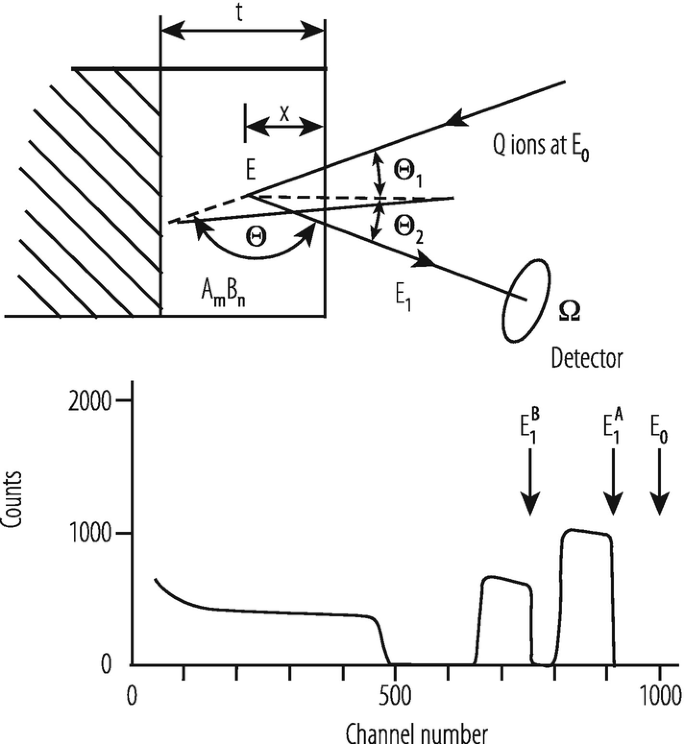
Schematic view of a RBS spectrum [39]
The sensitivity for low target masses is limited due to the underlying spectrum from the heavy substrate. The mass resolution is optimal for lower target masses, poor for heavier species and can also be limited by intrinsic detector resolution. For increasing beam energy the mass resolution improves linearly.
The depth profiling is dependent on the energy loss factor which incorporates the energy loss of the incoming and outgoing particles. Small energy loss factors result in large profiling depth, but limited resolution. The resolution is limited at high energy by the energy loss factor and at lower energies by an increasing energy straggling.
At high energies with broad resonances in the excitation functions the limitations are similar to the conventional backscattering.
Many other ions are suitable for RBS like 12C, 16O, 19F or 35Cl with energies >5 MeV. The beam energy has to be so chosen, that Rutherford cross sections can be applied. In some cases screening corrections are required particularly for heavy target species. Increased beam energy cancels potential increase in sensitivity arising from higher Z 1. It is less sensitive for lighter species than conventional backscattering due to increase in cross section. Mass separation improves with increasing beam energy. An increasing energy loss factor compared to light ions leads to shallower profiling depths and superior potential depth resolution. All target species heavier than the beam ion may be analyzed simultaneously.
The most frequently applied detector is the surface barrier detector. In some installations time-of-flight detectors are used.
A further well established method is ERD (Elastic Recoil Detection) which is also called Forward Recoil Spectrometry (FRES). In this process heavy projectiles are used to measure the content of hydrogen. For that method an accelerator with sufficiently high energy is required.
A general review of the methods of backscattering analysis is given e.g. by J.A. Leavitt et al. in [41].
Many nuclear reactions are used for the analysis of materials. In particular, those reactions which exhibit resonances in their excitation functions. By varying the energy of the projectiles to excite these resonances and exploit their enhanced cross sections, materials samples can be scanned with higher sensitivity.
A very special method of analysis is the charged particle activation analysis. In Table 11.2 [42] for a few particles, their energy and the reactions used are listed.
11.2.4 Accelerator Mass Spectroscopy
Many methods and also facilities which were developed for solving basic scientific questions have also found their way into the applications. One of these methods is the Accelerator Mass Spectrometry (AMS). It was developed for the measuring of very small ratios of radioisotopes to stable isotope concentrations by detecting atoms, rather than by detecting their radioactive decay. The samples which contain the isotopes under investigation are incorporated in the ion source either in gaseous form or as solid material in a sputter source. One characteristic isotope is 14C, which has a half life of 5760 years, and is used for age determination in many organic substances. Trees, e.g., incorporate also 14C as long as they live. From the analysis of the amount of remaining 14C the age of a piece of wood can be determined.
Tracing the radioactivity in organic substances can also determine e.g. metabolism or the paths of drugs and medicine. By measuring the concentration of the parent ions in beams, rather than their detecting radioactive decay products, AMS can determine values within the low 10−16 range for the ratio of 14C/12C. The accuracy is of the order of 0.3%. The measurements need much less time than detecting the radioactive decay products, an important factor in industrial application.
For industrial applications particularly compact instruments have been developed [42, 43].
As example—in Fig. 11.22 the installation of VERA (Vienna Environmental Research Accelerator) [42]—as a quite universal installation is shown. In this installation the measurement of negative as well as positive ions is possible. Particularly for the detection of 14C the measurement of negative ions is important. The mass difference of 14C and 14N is so small that a magnetic separation of both is impossible, but since nitrogen forms no negatively charged ions 14C appears as a very pure line in the spectrum.

Outlay of the VERA installation [42] (courtesy W. Kutschera)
Therefore the detection of 14C allows the analysis of pharmaceuticals which is one of the dominant industrial applications of AMS.
11.2.5 Conclusion
The present experience has shown that accelerators with energies below 100 MeV fulfill the needs of industrial applications because electron and ion beams can steer fabrication processes in much smaller areas compared to conventional methods. Particularly the well-defined energies and doses are essential for tailoring layered structures in some cases also with isolating layers.
11.2.6 Accelerator Suppliers
-
National Electrostatics Corp., Middleton, Wi, USA
-
High Voltage Engineering Europa B.V., Amersfoort, NL
-
Ion Beam Applications S.A., Louvain-la-Neuve, B
11.3 Accelerators in Medicine: Applications of Accelerators and Storage Rings
Electron and hadron accelerators are widely employed in the production of radionuclides—used in diagnostic and brachytherapy—and in teletherapy i.e. in the formation of radiation beams directed from outside the body towards tumours and malformations. In this section these two topics are discussed in a historical perspective by describing both, the status of the art and the challenges that accelerator developers have to face today to meet the highest standards in nuclear diagnostic and cancer therapy.
11.3.1 Accelerators and Radiopharmaceuticals
11.3.1.1 History
The years that followed the invention of cyclotron by Ernest Lawrence were very prolific in defining what would be later known as nuclear medicine. In 1932, Lawrence, Stand and Sloan were able to produce, with their new 27-in. cyclotron, a proton beam of 4.8 MeV. In 1934 two important discoveries influenced the future use of that accelerator, alpha-induced radioactivity by Frédéric Joliot and Iréne Curie [44] and the neutron-induced radioactivity by Enrico Fermi [45]. Those discoveries convinced Lawrence to fully employ its accelerated proton, deuteron, neutron, and alpha particle beams for the production of artificial isotopes.
The medical exploitation of the newly radionuclides was clear in Ernest Lawrence’s mind when in 1935 he called his brother John, a medical doctor from Yale school of Medicine, to join him in Berkeley to study the use of the new radioisotopes. Although the mainstream activity was nuclear research, a number of cyclotron-produced radionuclides was used for health applications in studies of physiology in animals and humans. The medical applications of radioisotope—radiotracing, endotherapy, and diagnostic—were defined at that time.
Radionuclides have the same chemical and physiological characteristics of the stable elements, so, when a radio-labeled organic compound is supplied to the organism, it follows the normal metabolism. From the mid 1930s, radionuclides were supplied to animals and humans and traced, with Geiger counters, in the internal organs following the physiologic uptake. Today the same concept is used in sophisticated diagnostics procedures as Single Photon Emission Computer Tomography (SPECT)—also called ‘scintigraphy’—and Positron Emission Tomography (PET). Since the pioneering years, the challenge was to find the right radioisotope that, as part of a molecule, would enter in the physiological processes and would be preferably taken by a specific organ. The right isotopes must be chosen for their half-life and decay type, both compatible with the physiology of the processes investigated, the detection procedure, and the radiation protection of the patient.
Radio Phosphorus-32 (beta-emitter with half-life of 14.3 days), made from the 27-in. cyclotron was used as a tracer to study the absorption and metabolism of phosphorus so that the cellular regeneration activity could be followed over several weeks [46]. In 1936 John Lawrence gave for the first time Phosphorus-32 to a leukemia patient beginning the therapeutic use of artificial radionuclides [47].
In 1936 radioactive Sodium-24 (half-life of 15 h), obtained at the Berkeley cyclotron bombarding ordinary sodium with deuterium, was one of the first artificial radioisotopes applied in physiology to study transport and uptake in animal and humans and to determine the speed of absorption on the circulatory system. Radioactive sodium was first given to treat leukemia patients by Hamilton in 1937 [48].
In those years radionuclides were also used to study the transfer of traceable elements and compounds across the cell membrane. Today cytopathology and molecular biology are using radiotracers to study cellular diseases and physiology.
Larger cyclotrons were produced in the late 1930s at Berkeley, Harvard, and Leningrad. Berkley’s 60-in. accelerator built in 1939 was used by Ernest Lawrence to produce radioactive gasses (nitrogen, argon krypton, and xenon) that were used to study the decompression sickness suffered by the aviators of the Second World War. The 81mKr gas is still used after 80 years in some studies of lung ventilation and functionality.
At the time of the first experiments in humans, the effects of X-rays on healthy biological tissues were known and avoiding overdose of ionizing radiation was a concern. It is important to mention that in 1936 John Lawrence, comparing identical doses of X-ray and neutrons [49], recognized different biological effects giving one of the earliest contribution to the knowledge of radiation qualities in correlation with internal and external radiotherapy and with radiation protection.
The isotope 131 of Iodine was selected by Joseph Gilbert Hamilton because its half-live of 8 days was considered to be the optimal time to treat the thyroid and avoid side effects to the patients. The radionuclide was isolated from a sample of tellurium bombarded with deuterons and neutrons from the 37-in. cyclotron. From 1941 Iodine-131 was used in diagnostic of thyroid functionality and, from 1946, in cancer therapy. In the 1950s Iodine-131, ingested as a liquid solution, became a common treatment. Commercially producer in nuclear reactors, it dominated for 40 years the market of radiopharmaceuticals for cancer treatment and it is still widely used today.
György Hevesy gave a decisive impulse to the studies with radiotracers of human metabolism and physiological processes. He carried on a program, supported by private funding, to introduce Sodium-24, Phosphorus-32, Cobalt-60, Technetium-99, and Iodine-131 into medical practice. In 1941 the first cyclotron fully dedicated to production of radionuclides for medical purposes was built at the Washington University of St Louis and used for the production of radionuclides for diagnostic and internal radiotherapy.
In the years that followed, the production of neutron-generated radioisotopes was moved to more efficient nuclear reactors. Nevertheless a number of cyclotron facilities, fully dedicated to medical applications, were built with the purpose of continuing the research of new products. In the 1950s, the use of Thallium-201 as tracer for cardiac flow revitalized the use of medical cyclotrons. Thallium-201 is produced via Lead-201 generator obtained in cyclotron from protons or deuterons beams.
In the late 1960s, a turning point that drastically transformed the medical application of cyclotrons was the idea of developing the radiochemistry labs inside the cyclotron facility, possibly close to the clinics where they were the patients were injected. Organic molecules containing short-living positron-emitting isotopes could be immediately transformed in pharmaceutical products and distributed in the facilities of the region to be used within few hours. The most important product was the Flourodeoxygloucose, FDG, made for the first time in 1976 with Fluorine-18, a positron emitter with a half-live of 110 min [50]. FDG was developed by a scientific collaboration of the Brookhaven National Laboratory, the US National Institute of Health and the University of Pennsylvania with the purpose of studying the brain metabolism.
Since then, FDG radiochemistry has evolved to fast and efficient production processes and today it is used in 75% of PET medical imaging [51]. The applications include diagnoses of brain diseases like epilepsy and dementia, examination of heart functionality, and detection of evolution of many different tumours.
New radiopharmaceuticals labeled with short half-lives positron emitters (in particular Fluorine-18 and Carbon-11) are still studied and developed today. Although Oxygen-15 is not commercially used for PET due to the fast decay time of 2 min, the Company Ion Beam Applications (IBA), built a 3 MeV deuterium cyclotron dedicated to the production of Oxygen-15 labeled gasses [52].
11.3.1.2 Accelerator for Radioisotope Production
Today the number of cyclotrons used for medical purposes, officially registered by the last IAEA survey published in 2006, is 262 [53]. The real number is certainly higher and it is increasing continuously by approximately 50 units per year, mainly because of new small PET accelerators. A survey made in 2010 combining inputs of production of the four major manufacturers already estimated in 671 the number of cyclotrons in operation [54].
The technology of cyclotrons has advanced in parallel to the development of PET. In the 1970s The Cyclotron Company (TCC) [55] studied the acceleration on negatively charged hydrogen (H−). The extraction of the beam is in this way simplified since it can be obtained with a thin stripping foil conveniently positioned on the beam trajectory. In the foil all electrons are stripped leaving the protons, positively charged, deviate to the opposite direction under the effect of the magnetic field. The result is a clean extraction with efficiency very close to 100%. The elimination of beam loss (of the order of 25% with normal extraction) drastically reduces the activation of the cyclotron components simplifying the maintenance, the regular inspection, and the decommissioning. A remarkable characteristic of these cyclotrons is the possibility of obtaining simultaneous multiple beams making partial extraction with additional more foils.

Examples of two commercial cyclotrons. (a) The self-shielded 7.8 MeV cyclotron GENtrace produce by General Electric (courtesy of GE Healthcare) for common PET radioisotopes. (b) The 30 MeV cyclotron Cyclone 30 produced by IBA for a variety of PET and SPECT radioisotopes (courtesy of IBA SA)
In recent years several companies entered into the production of cyclotrons, machines that are stable, reliable, and can run continuously for days with limited supervision and maintenance requirements. The accelerators design has been adapted to the radiopharmaceutical request that is mainly concentrate on PET products. The cyclotrons dedicated to production of Fluorine-18, Carbon-11, Nitrogen-13, and Oxygen-15, have abandoned the versatile characteristics of the traditional machines and are made to accelerate only a specific ion (typically H−), run at low energy (20 MeV and below), and at relative low current (approximately 100 μA).
Commercial cyclotrons characteristics are chosen taking into account the half-life of the radionuclides they produced. For the optimal logistics the cyclotrons should be homogeneously distributed in the territory with a large number of small cyclotrons, 10 MeV and 20 MeV, to fulfill the requests of FDG and other radiopharmaceuticals made on 18F, 11C, 13N, 15O, and a sparse distribution of cyclotrons with wider range of energy, 30 MeV or 70 MeV, able to produce all PET and SPECT radioisotopes used in research and in less common diagnostic (Fig. 11.23). Some of the higher-energy accelerators have the possibility of changing the energy moving the stripping foil along the cyclotron radius to adapt to the different nuclear reactions.
The commercial cyclotrons available today are presented here in two lists, Table 11.3 describes the cyclotrons in the range between 10 and 20 MeV, which correspond to the vast majority of machines today in operation for PET applications; Table 11.4 describes the cyclotrons with energies of 22 MeV and above for a more general use.
Besides cyclotrons, other particle accelerators have been considered for medical applications. Studies for low energy, high current accelerators have been financed in the 1980s, by the Star Wars program of the US Department of Defense. RFQ accelerators have been designed to obtain beam intensities of hundreds of milliampere at energies below 10 MeV. In the framework of the same program a 3.7 MeV, 750 μA Tandem Cascade Accelerator was designed, realized, and put into operation by Science Research Laboratory in Massachusetts for the production of Nitrogen-13, Oxygen-15, and Fluorine-18 for PET [58]. Today, AccSys Technologie proposes a linear proton accelerator for PET isotope productions. This RFQ accelerates protons to 3 MeV with a current of 150 μA. The energy can be upgraded to 10.5 MeV coupling the RFQ to a Drift Tube Linac (DTL). The system is suitable for supplying PET radioisotopes to a single diagnostic centre.
11.3.1.3 The Radionuclides Used in Nuclear Medicine
In the world the request of radionuclides for imaging is constantly increasing. Multimodality scanning systems have been favorably accepted by the medical doctors. The leading companies report that 35% of the SPECT scanners produced are sold combined with Computed Tomography (CT). In the same way the request of PET/CT and PET/MRI systems that combine metabolic and morphological imaging is stably increasing and so is the demand of positron emitter radionuclides. In the years to come many factors will contribute to define the role of accelerators in the commercial production of medical isotopes. Unforeseen events as the shortage of Molibdenum-99 described at the end of this section can weaken a situation that was considered stable. The primary role of reactors, to which it is ascribed approximately 80% of the medical radioisotope production, can be diminished by downsides as the rigidity of a centralized production, the risk of incident in nuclear power plant, and the problems connected to radioactive waste. These drawbacks are strongly reduced with radioisotope production based on accelerators and this can play in their favor.
Today PET imaging is certainly the largest medical use of the cyclotron radioisotopes. IAEA reports in its 2006 survey that 75% of the cyclotrons are dedicated to FDG [53]. Concerning SPECT, some radioisotopes for (gamma- and gamma/beta-emitters) are produced only with cyclotrons (Iodine-123, Indium-111, Gallium-67, Cobalt-57) some others, as Copper-67 and Rhenium-186, are produced both with cyclotrons or reactors.
Immuno-positron emission tomography is an imaging technique that, using radio-labeled monoclonal antibodies, allows tracking and quantifying their distribution in the body, and can be applied to imaging of human malignancies. Zirconium-89 has a primary role in immunoPET being used in most of the diagnoses based on radioactive antibodies [59]. Its favorable characteristics are a half-life of 3.3 days which allows a manageable production and distribution, and the favorable decay mode where the unavoidable gamma rays have energies well distinguishable from PET photons. Finally Zirconium-89 production, via proton-neutron reaction in Yttrium-89, is optimal at energies of 14 MeV, widely available in cyclotron facilities [see Table 11.3].
Radiopharmaceuticals for therapy represent only 5% of the total production [60], nevertheless the research in the field of cancer targeted radionuclide treatments is active and the role of cyclotrons is becoming more and more important. The isotopes that better conform to the therapy are those that decay transferring locally all their energy. The favorable decay products are alpha particles, beta particles and Auger electrons. The optimal radionuclide is selected based on essential characteristics, which are (i) the possibility to associate it to molecules or, in case of radio-immunotherapy, to monoclonal antibody, with affinity to tumour cells, (ii) the right decay time to allow the kinetics and avoid overdose, (iii) the availability of the product in reliable quantities, and (iv) the affordable cost. The research is trying to balance these demanding needs and the number of radionuclides under examination is getting large.
Alpha-particles emitters are Astatine-211, produced with the reaction 209Bi(4 2He,2n) by 28 MeV alpha particle beams, and Bismuth-212, obtained from a Actinium-225 generator produced with the reaction 226Ra(p,2n) by 22 MeV protons. Bromine-77, an Auger-electron emitter produced with either alphas (27 MeV) or protons (in various possible reactions starting at the energy of 13 MeV), is a good candidate for its simple association with physiological molecules. Among the beta emitters, Renium-186 is favorably regarded since, it belongs to the same chemical family of Technetium and therefore it can follow similar the chemical process well establishes for 99mTc.
Brachytherapy with radioactive seeds is an established way of endoradiotherapy based almost exclusively on reactor-produced radionuclides. One exception is Palladium-103, an Auger-electron emitter produced in reasonable quantities by 18 MeV cyclotrons.
Interest is rising in endoradiotherapy based on pre-therapeutic PET dosimetry. Two radioisotopes of the same element can be used for complementary proposes. First the pre-therapeutic positron emitter is injected to trace the physiological uptake of the element and then the therapeutic isotope is administered to the patient according to the dose estimation. Isotope pairs of Copper and Scandium (β+ emitted from 64Cu or 44Sc used for PET imaging, β− emitted from 67Cu or 47Sc used for therapy) are considered for these procedures [61].
It is important to underline the steering role played by the medical community in determining the future of diagnostic, with SPECT and PET, and of endoradiotherapy, which is today only a marginal segment. Medical doctors—who today use preferably one diagnostic modality, SPECT, and one radionuclide, Technetium-99m—with their future orientations will influence the development on new tools than could complement or substitutes the existing one. A challenge is also the complexity of transforming an effective radioisotope to an approved pharmacological product. The most important factors to consider are the availability and cost of the raw material, the access to accelerators or reactors with appropriate energy and fluxes, the existence of fast radiochemistry, and the logistic to delivery the radioisotopes on time before they decay.
To address the needs of the research of new medical applications, and also to partially take over the aging accelerators, some dedicated facilities have been put in place worldwide. Among others (i) ARRONAX in Nantes, financed by French regional and National authorities and the European Union, that hosts a cyclotron for H− (up to 70 MeV, 350 μA protons), H2 +, D−, and He++; (ii) LANSCE in Los Alamos, USA, that produces from 2005 medical radioisotopes from a high-current 100-MeV proton linear accelerator; (iii) the PEFP center in South Korea, a facility based on a 20 mA proton linear accelerator (an RFQ followed by two Drift Tube Linacs to energies of 20 MeV and 100 MeV) for medical and industrial applications.
A motivation for studying new applications of accelerators came from the worldwide shortage of Molybdenum-99, the generator of Technetium-99m. The production dropped to about 50% of the market needs for 16 months between 2009 and 2010. Commercial Molybdenum is a fission product of highly enriched uranium target produced almost exclusively in five reactors that are old and need continuous maintenance. Each year 30 millions diagnostic studies, 80% of all medical scans that use radioisotopes, are made with Technetium-99m (6 h half-life) from a Molibdenum-99 generator (66 h of half-life).
The shortage of Molybdenum-99 stimulated several initiatives for finding alternative solutions and the use accelerator was considered for the production of either Molybdenum-99 or directly Technetium-99m. If, from one side, a single accelerator facility is unable to compete in production with large reactors, on the other side it allows a better distributed production with advantages for the logistics, the possibility of producing directly technetium-99m for locally distributed end users, and undisputable environmental benefits. The accelerators considered for different productions processes are electrostatic accelerators, electron linacs, and cyclotrons.
Two Canadian initiatives were established to produce Technetium-99m trough the reactions 100Mo(p,2n)99mTc [62]. The projects use existing cyclotrons available for positron emission tomography (PET) from General Electric (130 μA, 16.5 MeV) and Advance Cyclotron Systems, Inc. (300 μA, 19 MeV) and the productions should start in 2017. The clinical trial which compared reactor- and cyclotron-produced Technetium-99m was concluded in 2017 receiving the approval from Health Canada.
Some project plan to substitute reactor-generated neutrons with accelerator-generated neutrons. To reach the capabilities of a reactor production, the neutron rate should exceed 1014 neutrons per second. The concept developed by the company Shine is based on the fusion of deuteron and tritium for producing neutrons (and helium). The electrostatic accelerated deuterons (300 keV, 60 mA) are directed toward a tritium target. The resulting neutrons (5·1013 neutrons per second) cross a natural uranium target for neutron multiplication and irradiate a low enriched uranium target producing, among other fission products, Molybdenum-99. The first facility is in construction phase.
The company NorthStar is developing a facility for the production of Molybdemum-99 from photo-nuclear reactions 100Mo(γ,n)99Mo using electron linacs. Two accelerators (40 MeV, 3 mA each) direct the electron beams from opposite sides to a Molybdenum-100 target where the bremsstrahlung photons are created. The production is expected to start in 2017 [63].
Another project linked to TRIUMF is the development of a high-current electron linac (50 MeV, 100 mA) for the generation of photons that, directed to a target of Uranium-238 produce Molybdenum-100 from photo-fission.
Electron linacs for the generation of neutrons are foreseen in different project from Shine (35 MeV, 0.6 mA), and Niowave (superconductive 40 MeV, 2.5 mA). The generated neutrons irradiate a target containing a solution of depleted uranium.
Several other ways of using accelerators for production of Molibdemun-100 or Technetium-99m have been proposed and are still under study and development[64].
11.3.2 Accelerators and Cancer Therapy
11.3.2.1 History
Conventional Therapy
The roots of brachytherapy (discussed in section 11.3.1.3) and teletherapy date back to the discoveries of X-rays and radium made by Roengten and the Curies in the years 1895–1897. X-ray tubes and gamma-ray sources were soon employed in medical or technological uses. Teletherapy with X-ray photons was performed to cure superficial tumours few years after the discovery.
The first electron linac was built in 1947 at Stanford by Bill Hansen and his group for research purposes [65] and was powered by a klystron produced by Varian. Soon after, this new tool superseded all other electron/photon sources. Also in 1947, in England, Fry and collaborators build a 40-cm linac that accelerated electrons from 45 to 538 keV [66].
In the years that followed, those two groups and others, in particular the group of John Slater at MIT, studied the parameters of the irises to improve the power efficiency of the structure and to adapt the traveling wave parameters of wavelength and phase velocity. Around 1950 megavoltage’ tubes were built and, complementing the ‘cobalt bombs’ entered clinical practice. The positive surprise was that, due to the longer ranges of the electrons—put in motion by the gammas of the beam mainly through the Compton effect—these ‘high-energy’ radiations had a much better sparing of the skin.
In those years a process was initiated to adapt the complex machines developed for research purposes to the clinical environment and to the treatment needs. After a short season in which the X rays of energy larger than 5 MeV were produced with medical ‘betatrons’, electron linacs, running at the by-now standard 3 GHz frequency, became the instrument of choice. Varian in 1960 produced for the first time a linac that, mounted on a gantry, rotated around the patient and in 1968 the first medical machine based on standing-wave acceleration.
From the side of the traveling-wave accelerators, further studies have improved the efficiency and the start up time of the radiation so that today both designs are still used in medical linac: the two major manufacturers, Varian and Elekta (see Table 11.5) produce accelerators the first based on standing-wave and the second on travelling-wave. The average accelerating fields are in the range 10–15 MV/m.
In 2017 about 12,000 [67] linacs are installed in hospitals all over the world and in the developed countries there is one linac every 200,000–250,000 inhabitants. It is interesting to remark that all the electron linacs used to treat patients are close, as far as the overall length is concerned, to the 27 km circumference of LHC.
About 50% of all tumour patients are irradiated as exclusive treatment or combined with other modalities so that radiotherapy is used every year to treat about 20,000 patients on a Western population of 10 million inhabitants. On average, 40% of the patients who survive 5 years without symptoms have been irradiated.
This enormous development has been possible because of the advancements made in computer-assisted treatment systems and in imaging technologies, such as CT imaging, PET scans, MRIs. The most modern irradiation techniques are the Intensity Modulated Radiation Therapy (IMRT), which uses 6–12 no coplanar and non-uniform X-ray fields, and the Image Guided Radiation Therapy (IGRT), a technique capable of following tumour target which moves, mainly because of patient respiration.
Varian is the worldwide market leader with more than 50% of the share of electron linac for radiotherapy. One of its last development, HyperArc, is an irradiation system in which the uniform prescribed dose is delivered in a single revolution of the gantry. The times are drastically reduced thanks to the computer assisted continuous variation of the beam intensity and the use of a multileaf collimator that adapts the irradiation fields to the requirement of the treatment planning.
Cyberknife produced by Accuray (USA) is an original development in which a robotic arm substitutes the gantry to support the accelerator. To reduce dimension and weight, a X-band, 6 MV linac is chosen. The resulting pencil beam can penetrate and aim to the tumour with the optimal direction to spare the organs at risk.
In helical TomoTherapy a narrow x-ray beam constantly irradiates the tumour while rotating around the patient and, at same time, produces an image of the patient organs. The combination with the movement of the couch creates the helical irradiation which is modulated in intensity and collimated by a multileaf system to conform to the requirements of the panning. In 2011 the company TomoTherapy has been bought by Accuray.
The so-called MRI-guided radio therapy, i.e. the simultaneous combination of radiation therapy treatment and MRI scanning, has been performed for the first time by the company ViewRay. The system based on a 6 MeV linac, employs a MRI with 0.35 T magnets. A similar system which combines a 1.5 Tesla MRI and a 7 MeV linac, was developed and built by a collaboration between Elekta, Philips, and several clinics from Europe and North America [68]. The advantages of MRI scanning are the capability of identifying movements of soft tissue and organs, which are not detectable with other imaging media, and the absence of ionizing radiation exposure. Today the average frame rate during dynamic acquisitions is of the order of 10–20 frames per seconds with spatial resolution of the order of 2 mm.
The major companies producing electron linacs for photon therapy and the characteristics of some of the most advanced models are listed in Table 11.5.
It must be mentioned that, because of the increase risk due to the non-negligible production of photoneutrons, the use of the 16–20 MV photons is limited to the cases for which the size of the patient and the depth of the tumour require it. In normal conditions 6–8 MV energies are employed.
Neutron Therapy
At variance with the case of conventional radiotherapy, the use of atomic nuclei to treat cancer has benefited of a long series of accelerator developments, which is still continuing today. This is the reason for which we focus, in this second Part, on hadron accelerators.
‘Hadron therapy’ (‘hadronthérapie’ in French, ‘hadronentherapie’ in German, ‘adroterapia’ in Italian, ‘hadroterapia’ in Spanish) is a collective word which covers all forms of radiation therapy which use beams of particles made of quarks: neutrons, protons, pions, and ions of helium, carbon, neon, silicon, and argon have been used for treating cancer. Furthermore, lithium and boron ions, as well as antiprotons have been investigated as potential candidates. ‘Hadron therapy’, ‘particle therapy’, ‘ion-beam therapy’, ‘heavy ion therapy’ and ‘light ion therapy’ are other terms often used to indicate the same procedure, and every performing facility has its favorite term.
The first hadrons used for treatment purposes are the neutrons. The time progression in implementing neutron therapy was so fast that is astonishing today. The neutron was discovered by James Chadwick in 1932. Soon after, Ernest Lawrence and his brother John were experimenting with the effects of fast neutrons on biological systems. Following a paper by Gordon Locher [69], who in 1936 underlined the therapeutic potentialities of both, fast and slow neutrons, at the end of September 1938, the first patient was treated at the Berkeley 37-in. cyclotron. The first study on 24 patients, which used single fractions, was considered a success and led to the construction of the dedicated 60-in. Crocker Medical Cyclotron. Here Robert Stone and his collaborators (Fig. 11.24) treated patients with fractionated doses using fast neutrons. The tuning of the dose to control the tumour and prevent, at the same time, the complication of the normal tissue was still developing. The dose given to healthy tissues was too high, so that in 1948 the program was discontinued [70].

Robert Stone is watched by John Lawrence while aligning a patient in the neutron beam produced by the 60-in. cyclotron
Neutron therapy was revived in 1965 by Mary Catterall at Hammersmith Hospital in London and later various centres were built where fast neutrons were used for many years. In particular in the 1970s radiation oncologists of Chicago worked with Robert Rathbun (Bob) Wilson, Fermilab Director, to build the ‘Neutron Therapy Facility’ at Fermilab based on the injector linac [71]. At Michigan University, Henry Blosser built for the Harper Hospital a proton cyclotron rotating around the patient.
The worldwide effort for high-current 40–60 MeV proton cyclotrons was large. However, at present, this technique is rarely used. The reason is the poor depth-dose distribution of fast neutron and the fact that, all along the path, the biological effects, due mainly to highly ionizing protons put in motion by the neutrons, are difficult to determine and tissue-dependent. As discussed in the following, carbon ion beams are a much better solution to deliver doses being highly ionizing particles, i.e. particles which have energy losses (Linear Energy Transfers—or LET—in the medical parlance) much larger than the electrons put in motion by X rays.
Thermal and epithermal neutron are also used in Boron Neutron Capture Therapy (BNCT). This cancer treatment is based in two subsequent procedures, first the injection of the boron carrier, conceived to be absorbed preferably by the tumour, and second the irradiation of the patient with low energy neutrons. Alpha particles resulting from the reaction 10B(n,4 2He)7Li release all their energy close to the point where they are originated affecting the tumour cells.
Proton Therapy
The use of protons in teletherapy was proposed in 1946 by Bob Wilson [72], who was asked by Lawrence to measure, at the Berkeley Cyclotron, proton depth-dose profiles. Describing the significant increase in dose at the end of particle range, the so-called Bragg peak, which had been observed 40 years before in the tracks of alpha particles by W. Bragg, Wilson recognized in his paper the advantages in treating tumours. The Bragg peak—which can be ‘spread’ with modulator wheels—can be used to concentrate the dose sparing healthy tissues better than with X-rays. It is interesting to remark that in his paper Wilson discussed mainly protons but mentions also alpha particles and carbon ions.
In 1954, the first patient was treated at Berkeley with protons, followed by helium treatment in 1957 and by neon ions in 1975 [73]. In these treatments—as in most of the following facilities—the beam was distributed over the target volume using ‘passive’ shaping systems, like scatterers, compensators, and collimators that were adapted from the conventional photon therapy. The first treatments consisted of irradiation to stop of the pituitary gland from producing hormones that stimulated some cancer cells to grow. Between 1954 and 1957 at Berkeley, under the leadership of Cornelius Tobias, 30 pituitary glands and pituitary tumours were treated with protons [74].
In 1957 the first tumour was irradiated with protons at the Uppsala cyclotron by Börje Larsson [75], but the facility that made the largest impact on the development of proton therapy is certainly the 160 MeV Harvard cyclotron, which was commissioned in 1949 (Fig. 11.25).

Picture of the just completed Harvard cyclotron. Many years later Norman Ramsey was awarded the Nobel prize, together with Wolfang Paul
The Harvard staff got interested in using protons for medical treatments only after proton therapy was started at both, LBL and Uppsala. In 1961, Raymond Kjellberg, a young neurosurgeon at Massachusetts General Hospital in Boston, was the first to use the Harvard beam to treat a malignant brain tumour.
The results obtained for eye melanoma—by Ian Constable and Evangelos Gragoudas of the Massachusetts Eye and Ear Hospital—and for chordomas and chondosarcomas of the base of the skull [76]—by Herman Suit, Michael Goitein and colleagues of the Radiation Medicine Dept of Massachusetts General Hospital—convinced many radiation oncologists of the superiority of protons to X rays in particularly for tumours that are close to organs at risk. In 2002, when the cyclotron was definitely stopped, more than 9000 patients had been irradiated and the bases were put in place for the following development of the field. The competences developed in Boston were soon transferred to the new hospital-based facility of the Massachusetts General Hospital, now called “Francis H. Burr Proton Therapy Center”, which is equipped with the first commercial accelerator for therapy—built by the market leader, IBA.
Soon after the start-up of the Harvard facility other nuclear physics laboratories in USSR and Japan assigned horizontal beams of their research facilities to proton therapy. As shown in Table 11.6 in 1984 the Paul Scherrer Institute, Switzerland, did the same. This facility has been fundamental to the progress of proton therapy with its pioneering realizations of the gantry to change the angle of the beam penetration and the active scanning [77], the technique that, avoiding passive elements, moves the pencil beam in three dimensions painting the tumour with Bragg spots (a short description of active scanning is provided in the following paragraph on dose distribution).
Not by chance the first hospital-based centre was built at the Loma Linda University (California), where the determination of James Slater lead to the agreement with Fermilab in 1986, to design and built the 7-m-diameter synchrotron which accelerates protons to 250 MeV.
A smooth conversion from a physics laboratory to a hospital facility took place in Japan. The University of Tsukuba started proton clinical studies in 1983 using a synchrotron constructed for physics studies at the High Energy Accelerator Research Organization (KEK). A total of 700 patients were treated at this facility from 1983 to 2000. In 2000, a new in-house facility, called Proton Medical Research Center (PMRC), was constructed adjacent to the University Hospital. Built by Hitachi, it is equipped with a 250 MeV synchrotron and two rotating gantries [78].
Light Ion Therapy
Ions heavier than protons, such as helium and argon, came into use at Berkeley in 1957 and 1975, respectively. At the old 184-in. cyclotron 2800 patients received treatments to the pituitary gland with helium beams: the lateral spread and range straggling being much smaller than in the proton case described before.
About 20 years later, argon beams were tried at the Bevalac in order to increase the effectiveness against hypoxic and otherwise radioresistant tumours, i.e. tumours that need deposited doses 2–3 times higher if they are to be controlled with either photons or protons (radiation oncologists speak of ‘Oxygen effect’). But problems arose owing to non-tolerable side effects in the normal tissues. After the irradiations of some 20 patients, Cornelius Tobias and collaborators decided to use lighter ions, first silicon for 2 patients and then neon, for 433 patients. Only towards the end of the program it was found that the neon charge (Z = 10) is too large and undesirable effects were produced in the traversed and downstream healthy tissues [79]. The Bevalac stopped operation in 1993 and, at the conclusion of this first phase of hadrontherapy, almost 3600 patients have been treated worldwide with pions, helium ions or other ions.
The larger effects that ions have with respect to the ones produced by cobalt-60 gammas of identical dose is quantified by introducing the ‘RBE’ (Relative Biological Effectiveness). RBE depends upon the cell type, the radiation used (particle, energy, dose) and the chosen effect. For a given cell type and effect RBE varies with the LET of the ionizing particles. Only at the beginning of the 1990s carbon ions (Z = 6) were chosen as the optimal ion type. Indeed light ions produce a radiation field which is qualitatively different from the ones due to either photons or protons and succeed in controlling also radioresistant tumours.
The carbon choice was made in Japan by Yasuo Hirao and collaborators of the National Institute of Radiological Science, NIRS [80], who proposed and built HIMAC (Heavy Ion Medical Accelerator in Chiba) in the Chiba Prefecture (Fig. 11.26).

HIMAC features two large synchrotrons, injected by a Alvarez linac, and three treatment rooms for a total of two horizontal and two vertical beams
In 1994, under the leadership of Hirohiko Tsujii, the facility treated the first patient with a carbon-ion beam of energy smaller than 400 MeV/u, corresponding to a maximum range of 27 cm in water. By the end of 2015 about 10,500 patients have been treated and it has been shown that many common tumours otherwise difficult to cure (e.g. lung and liver) can be controlled [81, 82].
In 1987 in Europe an important initiative was launched to create a full-fledged European light-ion therapy centre. The characteristics of the needed hadron beams were defined in a series of expert meetings. EULIMA, the European Light Ion Medical Accelerator project, financed by the European Commission, was led by Pierre Mandrillon and involved many European laboratories and centres. The European therapy synchrotron was never built but instead national-based projects in Germany and Italy were pushed through giving to the radiation oncologists facilities similar to the HIMAC at Chiba and the Hyogo Ion Beam Medical Center.
In 1993 Gerhard Kraft and colleagues obtained the approval for the construction of a carbon ion facility at GSI (Darmstadt), later called the “pilot project”. Hadron therapy started in 1997 and, at the time of the closure in 2009, 440 patients [83] were treated with carbon-ion beams. The medical and technical competences were both used to build the Heidelberg Ion-Beam Therapy Center (HIT), which started operation in 2009 [84] and transferred to Siemens Medical, which built the HIT treatment rooms. The main new features of the GSI pilot project where: (i) the active ‘raster’ scanning system [85]; (ii) the sophisticated models and codes that take into account the biological effects of each irradiated sub-volume in the treatment planning system; (iii) the in-beam PET system which determined ‘on-line’ the location and shape of the irradiated volume by detecting the β+ radioactivity produced by the incident carbon ions, mainly 11C and 15O [85,86,88].
11.3.2.2 The Bases of Cancer Radiation Therapy
The absorbed dose due to a conventional beam of photons has a roughly exponential absorption in matter after a slight initial increase. For instance, the highest dose for beams having a maximum energy of 8 MeV, is reached at a depth of about 2–3 cm of soft tissue and the dose is about one third of the maximum at a depth of 25 cm. Because of this non-optimal dose distribution, the unavoidable dose given to the healthy tissues represents the limiting factor to obtain the best local control of the pathology in conventional radiation therapy. In this connection, it has to be remarked that even a small increase of the maximum dose can be highly beneficial in terms of tumour control.
The radiation is given to the patient balancing two opposing goals, deliver a sufficient dose to control the tumour and spare the normal tissue from dose levels that could cause complications. To increase the dose to the tumour and not to the healthy surrounding organs it is essential to ‘conform’ the dose to the target. In order to selectively irradiate deep-seated tumours with X-rays, radiation oncologists use multiple beams from several directions (portals), usually pointing to the geometrical centre of the target. This is achieved by using a mechanical structure containing the linac which rotates around a horizontal axis passing through the isocentre (‘isocentric gantry’). The already mentioned IMRT makes use of up to 6–12 X-ray beams; the beams may be non-coplanar and their intensity is varied across the irradiation field by means of computer-controlled multi-leaf collimators [89].
The depth-dose curves of proton and light ion beams are completely different from those of X-rays, because these charged particles give the highest dose near the end of their range in the Bragg peak, just before coming to rest. Figure 11.27 illustrates how hadrons are more suitable to treat deep-seated tumours as they can be used to target profound regions preserving the more superficial healthy tissue.

Comparison of depth dependence of the deposited dose for each radiation type, with the narrow Bragg peak at the end. For monoenergetic beams, the carbon peak is three times narrower than the proton beam, a feature which is not represented in this schematic drawing
In order to reach depths of more than 25 cm in soft tissues—necessary to treat deep-seated tumours—proton and carbon ion beams must have an initial energy not lower than 200 MeV and 4500 MeV (i.e. 375 MeV/u), respectively. In practice, the standard maximal energies are 230 MeV for protons and 400 MeV/u for carbon ions, which correspond to a 32 cm and 27 of water range, respectively. The minimal energies, used for shallow tumours, are 60 MeV and 100 MeV/u respectively.
For this reason sizeable particle accelerators are needed in hadron therapy. These machines are not demanding in terms of output current since 2 nA and 0.2 nA are sufficient for treating patients with protons and carbon ions, respectively, when active spreading systems are used. Higher currents are needed for ‘passive’ delivery systems in which the beam is reduced in energy with a variable absorber, spread by multiple scattering with two ‘scatterers’ and transversally shaped with collimators.
Cyclotrons have to produce 10–20 times larger currents. In fact the machine output energy is fixed and absorbers of variable thickness have to be inserted in a 15–20 m long Energy Selection System which reduces the energy to the treatment requirements. In the process of beam degrading, down to the minimal required energies, and re-shaping a large fraction of particles is lost.
As mentioned above, carbon and other light ions have a larger RBE with respect to X-rays and protons. The physical and radiobiological arguments of this can be summarized as follows. In a cell, a carbon ion leaves about 24 times more energy than a proton having the same range. This produces—very close to the particle track—a dense column of ionization, especially near the Bragg-peak region of the track, causing many ‘Double Strand Breaks’ and ‘Multiple Damaged Sites’, when crossing the DNA contained in the cell nucleus. In this way, the effects on the cell are qualitatively different from the ones produced by sparsely ionizing radiations, such as X-rays and protons. In addition, the biological effect of carbon ions is less dependent of the oxygenation of the target and therefore their use is indicated against hypoxic and otherwise radio-resistant tumours.
Due to the much more complex DNA damage, the RBE values of the light ions at the Bragg peak can be about three times larger than the one for X-rays and protons. In the slowing down of an ion in tissue this effect becomes important when LET becomes larger than about 20 keV/μm. For carbon ions this happens in the last 5 cm of their range in water.
11.3.2.3 Cyclotrons and Synchrotrons in Hadron Therapy
Proton Therapy
The first facilities that treated patients with protons and ions were based on existing accelerators built for fundamental research in nuclear and particle physics: LBL at Berkeley (USA); GWI in Uppsala (Sweden); JINR in Dubna (Russia); PMRC-1 in Tsukuba (Japan); UCL, in Louvain La Neuve (Belgium); MPRI-1 in Indiana (USA) 60 MeV protons at Chiba (Japan). Moreover pions where used at TRIUMPH and PSI (SIN at that time) in the periods 1979–1994 and 1980–1993, respectively. The clinical results have shown that pions are not superior to protons and light ions neither to obtain conformal dose volumes nor in the treatment of radioresistant tumours.
The proton therapy facilities running in the world are listed in Table 11.7. The data are extracted from PTCOG online database [90] and the data on the number of patients are updated to December 2015.
Table 11.7 includes three centres producing 60–70 MeV proton beams which are exclusively used for the treatment of eye tumours and malformations. The most recent facilities in the table are hospital-based, in the sense that they feature an accelerator built specifically for medical purposes and have more treatment rooms so that several hundred of patients can be treated every year. The companies which have built the accelerators and the high-tech parts of these centres are: Optivus (USA), IBA (Belgium), Varian/Accel (USA/Germany), Hitachi (Japan), and Mitsubishi (Japan).
A centre by IBA, which is the market leader of protontherapy, is shown in Fig. 11.28.

An Ion Beam Applications (IBA) proton therapy centre featuring two gantries and a fix-beam room (insert at the bottom left). The magnetic channel, called ESS (Energy Selection System), is needed to reduce the 230 MeV proton energy produced by the cyclotron (insert at the bottom right) to lower energies, down to 70 MeV (with courtesy of IBA SA)
The PTCOG is the organization, which associates experts from the technical and the clinical sectors in the field of hadron therapy. In its website [90] statistics on patients and the information about new proton and carbon-ion centres are updated with data from the companies and the clinics. By summing the numbers of all the centres in operation and out of operation one obtains that the number of patients treated with protons until the end of 2015 exceeded 131,000.
The most recent figures show that 39 new proton therapy centres are in construction and should start operation within 2020 while 24 more centres are planned. The geographical areas of major expansions are the USA with nine new centres under construction, China with seven, UK with six, and Japan with four. Proton therapy will be performed for the first time in Danemark, the Netherland, and Slovak Republic, and, outside Europe, in India, Saudi Arabia, Singapore, and Taiwan. Centres are planned to be built for the first time in South America (at the Instituto de Oncologia Angel Ruffo Hospital, Boenos Aires, Argentina), in Australia (at the Australian Bragg Centre for Proton Therapy and Research in Adelaide), and in North Africa (at the Children’s Cancer Hospital Foundation, Cairo, Egypt).
Carbon-Ion Therapy
As far as carbon ions are concerned, the situation is summarized in Table 11.8. It is worth remarking that all these centres have the possibility of treating patient with both, carbon-ion and proton beams, so that it the name ‘dual centres’ are more appropriate than ‘carbon-ion centres’. Several centres opted to use in clinic exclusively carbon ions in particular in Japan where the number of proton therapy facilities is large and well distributed in the territory.
NIRS promoting role has continued after the first experience of HIMAC and its activity was instrumental in the development and consolidation of carbon-ion therapy in Japan. Starting in 2004, NIRS was involved on the design of a new compact carbon-ion synchrotron. The new machine, that was employed for the first time in Gumna, is adapted to the medical use accelerating carbon ions up to 400 MeV/u and has a circumference of 63 m, more than two times smaller than HIMAC accelerator which was conceived for silicon ions up to 800 MeV/u [91]. Mitsubishi is commercializing the accelerator offering a complete turn-key solution as implemented in Saga-HIMAT. The centre Kanagawa i-ROCK is the result of the partnership of NIRS and Toshiba.
Not linked to NIRS developments is the synchrotron-based facility of HIBMC in Hyogo, which was developed by Mitsubishi and is in operation since 2001. This was the first clinical centre featuring dual modality, protons with energy between 70 MeV and 230 MeV and carbon ions between 70 MeV/u and 320 MeV/u.
Today the five carbon-ion therapy centres in operation in Japan treat, combined, more than 2000 patients each year, with a total at the end of 2016 of 18,000 treatments [92].
Built by Siemens Medical, the centre of HIT in Heidelberg applies the competences developed by GSI for its pilot project including the active scanning capabilities. This is the first dual centre featuring a gantry. Its construction has been a real challenge since it weighs 600 tons and consumes, at maximum energy, about 400 kW. The dual centre of Magburg was initiated as the second centre of Siemens Medical, and, when the company withdrew from hadron therapy it was bought by Marburger Ionenstrahl-Therapiezentrum which recommissioned and started treating patients in 2015.
In 1996 the Proton Ion Medical Machine Study (PIMMS) [93] was initiated at CERN with the participation of TERA Foundation (Italy), MedAustron (Austria), and Oncology 2000 (Czech Republic) to study a proton and carbon-ion accelerator for the therapy. The project of the high-tech part of the Centro Nazionale di Adroterapia Oncologica (CNAO)—shown in Fig. 11.29—is due to the TERA Foundation [94] which in 2002 obtained the financing of the centre by the Italian Health Minister. The synchrotron, features a unique ‘betatron core’ to obtain a very uniform extracted beam. The centre, built in Pavia, treated the first patient with protons in 2011, a year later, treated the first patient with carbon ions. The MedAustron centre built in Wiener Neustadt, uses the synchrotron design of CNAO and treated the first patient with proton beams in December 2016.

Above. CNAO has been built in Pavia by the CNAO Foundation in collaboration with INFN, the Italian National Institute for Nuclear Physics. To reduce the overall dimensions, the 7 MeV/u linac (built by GSI) is placed inside the 25 m diameter synchrotron. Below, MedAustron built in Wiener Neustadt (© Kästenbauer/Ettl.): the same synchrotron structure of CNAO hosts sources and the linac in a separate room, not visible in the picture
A new carbon-ion therapy facility is under construction in China (HITFil, Lanzhou). A dual center will be operational starting in 2018 in South Korea (KIRAMS, Busan). By the year 2020 two more carbon-ion centres will be operational in Japan, in the cities of Osaka and Yamagata. All these centers are based on synchrotrons.
Dose Distribution Systems
In order to maximize the outcomes of the therapy, the optimal hadron accelerators systems should deliver a biological equivalent dose defined with an uncertainty lower than 5% to tumour volumes that varies from few cubic milliliters up to 2 L preserving as much as possible the healthy surrounding tissue. The desirable dose rate is 2 grays/min/L, where 1 Gy = 1 J/kg.
Till the end of the last century, in all facilities, except PSI, the conformation of the dose to the tumour was realized with ‘passive’ dose delivery systems, using individually machined collimators, boluses, and passive absorbers to spread longitudinally the Bragg peak. With this technique, which is still widely used, the same spread out Bragg peak applies to the whole transversal section of the tumour, so that large volumes of healthy tissue, that surrounds the tumour, are exposed to the same dose as the tumour tissues.
Modern system have been develop to minimize the over dosage of the healthy tissue. The spot scanning technique developed for protons by PSI and the raster scanning technique developed for carbon ions by GSI operate dividing the whole region to be treated in sub-volumes of the order of few cubic millimeters (named voxel from volume cells), directing beams with reduced transversal section (pencil beams) toward them, and delivering a dose that is varying from one position to the next. To further minimize the dose to healthy tissue the radiation is directed to the patients from several directions (typically three). These techniques, which have various practical realizations, are collectively called ‘active dose spreading systems’.
The accelerating systems that realize such treatments require the highest beam stability, the possibility of changing promptly and frequently beam intensity and energy eider acting on the acceleration or using passive Energy Selection Systems with rapidly moving absorbers.
A recent development that resulted from the common effort of NIRS and HIMAC is the implementation of fast active spot scanning system. The fast beam scanning speed of 100 mm s−1 allows a high repetition rate of the scanning spots so that a ‘volumetric multipainting’ of the tumour target is achievable. One-liter tumour volume at a rate of 100 Hz can be repainted by the pencil beam several times in few minutes reducing the statistical uncertainty in the delivered dose by a factor \( \sqrt{n} \) (where n is the number of re-paintings) and minimizing any local accidental under-dosage or over-dosage. This method also improves the synchronization of the irradiation with the breathing movements. A second development concerns the superconductive gantry. The structure, studied for carbon-ion beams up to 430 MeV/u, has a radius of 5.5 m and a wait of approximately 200 tons, comparable with normal-conductive proton therapy gantries and sensibly lighter than the 600 tons gantry built in Heidelberg.
The ultimate goal is the treatment of moving organs, a challenge that is more critical in hadron therapy than in conventional therapy because of the dose is concentrated in the Bragg peak. In this case the accelerating system and beam delivering system require a feedback that, based on on-line movement detection, adapt in few milliseconds the beam characteristics to the three dimensional movements of the target.
11.3.2.4 Present and Future Challenges
There is still space for improving the dose delivery, for instance, the active dose delivery systems for protons and carbon ions have been used for a small part of the patients treated with protons or ions. In spite of the fact that most new centres are featuring ‘active’ scanning systems and some of the existing centres are upgrading to them, the implementation in the clinical practice has been for many years quite slow.
As far as the accelerators and transfer lines are concerned, two main lines of research have to be intensively pursued:
-
systems which actively scanned are able to follow the tumours which are subject to movements,
-
accelerator and delivery systems which are lighter, smaller, more efficient, and less power consuming than the present cyclotrons
Fast Cycling Accelerators to Follow Moving Organs
In conventional radiotherapy various techniques have been introduced to determine in real time the position of an irradiated tumour which moves, for instance, because of the respiration cycle and to deliver the dose following these movement in IGRT. In this case computer controlled multileaf collimators are used. In hadron therapy the tumour position can be detected with the same methods and a better follow-up can be obtained by rapidly moving the Bragg spot so to compensate for three-dimensional movements.
In the transverse plane the active scanning of tumours with hadron pencil beams is obtained by adjusting two perpendicular magnetic fields located many meters upstream of the patient. The time needed to move the beam transversally, following the indication of a precise feedback system, is of the order of milliseconds.
Due to the respiration cycle, the target organs can also move longitudinally, i.e. in the direction of the beam. A good example of the problems concerning the movements is a rib which enters the irradiation field of a lung tumour. In cyclotrons and synchrotrons the time needed to change the energy, and thus the depth of the Bragg peak, is of the order of 1 s because of the delay necessary either to move energy absorbers (in cyclotrons) or to change the energy (in synchrotrons). An accelerator with an energy cycle of the order of a few milliseconds would allow a longitudinal follow-up of the tumour similar to the transversal one.
In synchrotrons, the beam is delivered to the treatment rooms only for fraction of the machine time. Ramping up and down the magnets after the extraction of the beam and waiting for the magnetic field to stabilize are time-consuming operations. Few seconds are needed in this procedure and to reduce this dead time the centre of HIT studied a system in which probes for the measurements of the field in the magnet were inserted on the feed-back loop of the regulation of the magnetic fields in the elements of synchrotron and beam lines. The result was an overall increase in efficiency of 24% and a reduction of the time between two successive extractions to approximately 1 s. If such time intervals are still not compatible with movement compensation, nevertheless the improved efficiency has important impacts on the facility, since a larger number of patients can be treated and the cost per treatment decreases [95].
NIRS and HIMAC optimized the efficiency of their extraction system allowing to extract of multiple energies, during a single machine cycle [96]. It is important to remind that, in a treatment based on active scanning, the first layer irradiated is the deepest, and then step by step all other layers. The number of particles accelerated to certain energy in general exceeds the total number needed for irradiating the corresponding layer at the planned dose. The beam not used is dumped and this corresponds also to a waste of time. At NIRS, a system was studied to avoid beam dumping using the synchrotron to decelerate and use the remaining beam to the next more superficial layer. The process takes approximately 100 ms and, since the procedure can be repeated several times within the same beam cycle, the optimization of the irradiation time is consistent. Similar techniques are feasible to compensate tumour movements.
Recently two new fast cycling accelerators—particularly suited for the movement compensation and repainting of moving organs—have been considered: high frequency linacs and Fixed Field Alterenating Gradient (FFAG) accelerators.
Since 1993 the linac approach is pursued by the TERA Foundation with the choice of using the same frequency (3 GHz) employed in the construction of electron medical linacs [97]. Since the acceleration of very low velocity protons (and carbon ions) is problematic, it was proposed to use as injector a commercial 30 MeV cyclotron. The cyclotron-linac complex has been dubbed ‘cyclinac’. Between 1998 and 2003 a TERA, CERN, INFN collaboration built and tested a 3 GHz 1-m long side-coupled standing-wave structure which accelerated protons from 62 to 74 MeV [98] and could stand gradients as large as 27 MV/m, corresponding to surface electric fields larger than 150 MV/m. In parallel an all-linac solution was studied by L. Picardi and collaborators [99] which has been adopted for the TOP-IMPLART a proton-therapy facility under development at the Laboratories of Enea, in Frascati, Italy. The 150 MeV linac will be installed in the IFO Hospital, in Rome.
In the last years various cyclinacs have been designed: for proton therapy a 15-m long linac could be used to accelerate the protons between 30 MeV and a maximum of 230 MeV. A second cyclinac design is based on a superconducting cyclotron that accelerates carbon ions C+6 (and H2 + molecules) to 150 MeV/u (Fig. 11.30) with a 300–400 Hz repetition rate [100]. The linac is subdivided in modules, which interspaced with permanent magnetic quadruples are so short that the beam energy can be continuously varied in a couple of milliseconds between the cyclotron energy and the maximum by varying the output power of the klystrons.

This design of CABOTO (CArbon BOoster for the Therapy in Oncology) features a 150 MeV/u superconducting isochronous cyclotron followed by a 5.7 GHz standing-wave linac powered by seventeen 12 MW klystrons (courtesy of TERA Foundation)
Fixed Field Alternating Gradient (FFAG) accelerators have been proposed as fast cycling accelerators for hadron therapy since the magnetic fields of the ring are constant in time—as in a cyclotron—and the frequency of the accelerating electric field can vary up to 500–1000 Hz. The many bending magnets are arranged in triplets: the central magnet bends the circulating beam inwards while the two external ones bend it outwards. During acceleration the orbits maintain the same oscillating shape but increase in average radius so to remain inside the wide vacuum chamber and find stronger and stronger deflecting fields. In the recent ‘non scaling’ FFAGs the orbits of increasing radius do not maintain the same shape so that the full excursion requires bending magnets which are radially smaller than in classical ‘scaling’ FFAGs. It has to be noted that in every case beam extraction at different energies needs fast kickers [101].
A 150 MeV FFAG has been built in Japan for high-current applications [102] and low-current uses of non-scaling FFAGs in proton therapy have been proposed [103, 104].
In the case of carbon ions, due to the high magnetic rigidity of the beam, a solution with three concentric non-scaling FFAG machines has been studied [105]. In this case there is the added complication of the many injection and extraction systems which are needed in multi-ring facilities. This and other arguments are discussed in a recently published comparison between linacs and FFAGs for hadron therapy [106].
Compact Accelerators and ‘Single Room’ Facilities
An important line of development concerns what are now known as ‘single room’ proton facilities. The rational can be best appreciated by browsing Table 11.9 which has been constructed by using the results of the epidemiological studies performed in Austria, France, Italy and Germany in the framework of the EU funded network ENLIGHT [107]. They can be summarized by saying that in the medium-long term about 12% (3%) of the patients treated with high-energy photons would be better cured with fewer secondary effects if they could be irradiated with proton (carbon ion) beams. The table presents the number of treatment rooms needed for a population of 10 million people living in a developed country. The estimated numbers of rooms turn out to be in the easy to remember proportions 1:8:82. Since a typical hadron therapy centre has 3–4 rooms, the above figures tell that a proton (carbon ion) centre would be needed every about 5 (40) million people.
For proton therapy this shows the way to a flexible and patient-friendly solution: instead of a multi-room centre with its large building, one should develop single-room proton accelerator/gantry systems, constructed on a relatively small area (approximately 500 square metres) attached to existing hospital buildings homogeneously distributed in the territory. It is worth remarking that the overall cost of a full proton (dual) centre with three treatment rooms is of the order of 100 M€ (200 M€). Single-room proton therapy facilities, which cost approximately 25 M€ [108] are strategic for the future expansion of proton therapy in existing clinical facilities where cost and size is the most important factors.
Single room facilities are offered by Mevion, IBA, Varian, Sumitomo and other companies. Two lines of developments have to be considered: compact accelerators followed by short magnetic channels and accelerators which rotate around the patient.
A very high field 15-tons niobium-tin superconducting 250 MeV synchrocyclotron was developed by Mevion Medical Systems Inc. in collaboration with the Massachusetts Institute of Technology (MIT) and the Massachusetts Medical Hospital. Mevion S250 is the firstly constructed system based on the concept of single-room facility which treated the first patient in December 2013. The accelerator is mounted directly on the 190° isocentric gantry (Fig. 11.31a) with a superconductive coils producing a 8.7 T central magnetic field. The first version of the system which featured a passive beam delivery system has been updated to a ‘pencil beam’ system for active scanning.

Single-room facilities commercialized by MEVION, IBA, and Varian
The Proteus ONE system of IBA consists of a compact 230 MeV superconducting synchrocyclotron, named S2C2. The energy selection system is mounted on the 220° isocentric gantry (Fig. 11.31b). In September 2016 the Lacassagne Centre in Nice treated the first patient with S2C2 accelerator.
The single-room system ProBeam of Varian system combines a 250 MeV cyclotron—the first commercial superconductive accelerator developed for proton therapy used at PSI since 2007—and the 360° gantry (Fig. 11.31c).
A proposed system is the high-frequency proton linac rotating around the patient—according to a scheme named TULIP and patented by TERA [109] which is based on the same 5.7 GHz linac designed for CABOTO (Fig. 11.32).

TULIP (Turning LInac for Proton therapy) all-linac solution (courtesy of Mohammad Vaziri—TERA Foundation)
An original development concerns laser-driven ion beams and is based on protons accelerated by illuminating a thin target with powerful (1018–1020 W/cm2) and short (30–50 fs) laser pulses. When the laser pulse hits the target—with thickness of the few micrometers—electrons are violently accelerated producing an electric field of the order of teravolt per meter which draws behind the protons for the surface of the target itself. The phenomenon has been studied experimentally reaching proton energies of more than 10 MeV with promising results [110]. The energy spectrum is continuous and computations show that, using proper combination of target shapes and laser power, a 3% energy spread can be obtained [111]. The advantages of a laser-driven system are that the ion beams can be generated very close to the patient and that optical elements can substitute the cumbersome and heavy beamline elements including the gantries. The most relevant challenge is probably the short pulse duration which is linked to the unknown biological effects of the high dose rates, the impossibility of controlling the beam intensity during the irradiation, and the potential risk of overdose. An important issue is also linked to very low repetition rate of few hertz which would extend the irradiation to unacceptable time. The implementation process is complex and still several years are foreseen to create, around the laser-driven 200 MeV proton beam, the whole infrastructures for a therapy facility [112].
Acknowledgment
The authors are grateful to the International Atomic Energy Agency and in particular to Joao Alberto Osso and Amirreza Jalilian for the discussions and for providing statistics and data on worldwide radioisotope production, to Eiichi Takada and Hikaru Souda for the information about the recent developments on carbon-ion therapy accelerators in Japan, and to Saverio Braccini for the precious contributions and comments he provided on the text.
11.4 Spallation Sources
11.4.1 Introduction
Spallation is a nuclear process in which neutrons at different energies are emitted in several stages following the bombardment of heavy nuclei with highly energetic particles. In this chapter we limit ourselves to the description of the accelerator that drives spallation sources. For a more detailed discussion of the spallation process itself, the target, the moderators and the physics at such facilities see (for example) [113]. However, it is worth noting that there are other ways to produce neutrons with accelerators, for example photo-fission induced by an intense electron beam. The spallation process is the most practical and feasible way of producing neutrons for a reasonable effort (or simply cost) of the neutron source cooling system, see Table 11.10. Research reactors also require fissile material handling, potentially a major constraint for both handling and licensing.
Spallation sources come in at least three types: short pulse sources (a few μs), long pulse sources (a few ms) and continuous sources. In general, synchrotrons or accumulator (compressor) rings provide short neutron pulses, linear accelerators provide long neutron pulses, and cyclotrons provide continuous beams of neutrons.
Pulsed neutron sources are more efficient in their use of neutrons than continuous sources, in a majority of all applications, according to a survey performed for the Autrans meeting in 1996 [115]. The time-of-flight of the neutrons—readily measured from a pulsed source—allows us to determine the neutron speed and energy. Additional tools are needed to select or determine the neutron speed in a standard research reactor source. For example, a pulsed structure can be achieved by chopping a continuous beam with a shutter. Consequently many of the neutrons are then lost. Figure 11.33 plots the instantaneous neutron flux at different facilities as a function of the year of their completion. It is not possible to extract the average neutron flux from the figure without detailed knowledge of the time structure of the different facilities. However, the future European Spallation Source (ESS) will be the first spallation source with a time average neutron flux as high as that of the most intense research reactors.

The instant neutron flux at different research facilities plotted as a function of time
The spallation cross section for protons on heavy nuclei increases as a function of proton energy up to several tens of GeV [116]. Nonetheless it is generally agreed that a kinetic proton energy between 1–3 GeV is optimal for practical target and moderator designs, and in order to keep the shielding requirements reasonable.
The first spallation source, ZING-P, based on a synchrotron, was built and operated at the Argonne National Laboratory. It provided a short pulse well suited for Time-Of-Flight (TOF) techniques at the “instruments” (experiments). Spallation sources at Argonne were superseded by the Intense Pulsed Neutron Source (INPS), by the KEK Neutron Science Center (KENS) in Japan, and by the ISIS neutron facility at Rutherford in UK. These synchrotron based spallation facilities were recently exceeded in power by J-PARC, at Tokai in Japan.
The first linear accelerator used to provide protons for a spallation source − the Los Alamos Meson Physics Facility (LAMPF) in the USA − later became the Los Alamos Neutron Science Center (LANCSE). The highest power Spallation Neutron Source (SNS) in Oak Ridge combines a full energy linear accelerator with an accumulator ring to provide very high intensity short pulses of neutrons to the instruments. The European Spallation (ESS) source will provide even higher intensities, but is developing instruments able to use longer linac pulses directly for spallation, avoiding the need for a costly and performance-limiting accumulator ring [117]. Synchrotrons and accumulators, alike, have a intensity limits due to space charge effects that introduce tune spreads and cause beam instabilities, resulting in significant beam losses.
11.4.2 The Linear Accelerator
For many spallation-based sources, a good choice of technology for the acceleration of the proton beam is a linear accelerator (linac). These very complex machines are conceptually quite simple—a beam of H+ ions or protons is generated by a source and passed through a series of accelerating structures on its way to the spallation target. Since the spallation process means that the time structure of the neutron pulses will match that of the proton beam, the requirements of the experiments directly dictate the time structure of the proton current, and thus the high-level design of the linac.
11.4.2.1 High-Level Machine Design
Typically the specifications given by the experiments are the following.
-
The desired repetition rate of the facility, usually less than 120 Hz.
-
The duty factor or the length of the neutron pulses.
-
The beam power on target; either average or maximum.
Given these parameters, the accelerator designers then begin sketching out the specifications of the design.
Kinetic Energy and Current
The maximum beam power on target constrains the maximum energy and current of the proton beam, and engineering capabilities will place additional limitations on these quantities. For example, the spallation target may have an energy threshold beyond which it will no longer survive.
As mentioned previously, the optimal beam energy for a spallation target system is in the range 1–3 GeV, and so an accelerator designer is likely to pick an energy in this range. From this, the required beam current is easily derived.
After this, these parameters will be optimised in an iterative way. Engineering limitations will first be reached in either the power transmission capabilities of the couplers on the accelerating structures, or the acceleration gradients required within the cavities. Once these have been determined, the designer can iteratively tweak the beam energy and current in order to balance the performance requirements of the cavities.
RF Frequency
Due to unavoidable losses in the generation and transmission of the RF, the installed capability will need to be more than a factor of two larger than the beam power. The high power nature of these machines means that one of the largest cost drivers will be the power sources for the accelerating RF. In order to save cost it is advisable to take advantage of already-designed components, and thus RF frequencies previously adopted by other facilities.
Typically this results in acceleration RF whose frequency is an integer multiple of 176.105 MHz or 201.5 MHz.
Since it is possible to achieve higher acceleration gradients with higher frequencies, the self-force (i.e. space charge) of the beam at the lower energy regions of the machine mean that the strong focusing that results from high frequencies can be problematic. It can therefore be optimal to use multiple acceleration frequencies, with that in later sections of the linac being a multiple of two or four of the low energy acceleration.
11.4.2.2 Linac Layout
A linac is laid out as a series of consecutive stages of acceleration. The following sections each provide some detail on the most common technologies.
Proton Source
The ion source for a long pulse spallation source delivers protons rather than H- ions, since there is no need to inject into an accumulator ring using charge exchange injection (see section on synchrotrons). Proton sources can be implemented using various techniques. For example, compact Electron Cyclotron Resonance (ECR) sources such as VIS [118] and SILHI [119] are well suited to the task, delivering continuous proton beams of up to 100 mA. The diverging beam leaving the source has to be transported and matched to RFQ, usually using Einzel lenses or solenoids in the Low Energy Beam Transport (LEBT). The LEBT has to be designed carefully because it defines the beam quality throughout the rest of the linac [120].
Radio Frequency Quadrupole
Modern proton sources typically output a continuous beam of protons, however it is not possible to directly accelerate such a CW current. The structure immediately following the proton source must be one that compresses the current into a series of bunches at the fundamental frequency of the accelerating RF. In the majority of linacs a Radio Frequency Quadrupole (RFQ) performs this job.
An RFQ is a resonant cavity loaded with four vanes or rods in such a way that the beam experiences a quadrupolar electrical field that strongly confines the size of the beam. These vanes or rods are modulated in such a way that the beam also experiences longitudinal forces. Initially these forces are tuned so that the continuous current will begin to coalesce into a series of bunches at the frequency of the accelerating RF.
As the beam proceeds further through the RFQ, the modulation of the vanes/rods will be adapted so that there will be an acceleration force in addition to the focusing terms. This will be increased throughout the length of the RFQ in a way that preserves the quality of the beam, while keeping the structure to a reasonable length.
For a given frequency the four-vane structure is the most power efficient, for low current applications 4-rod structures may be cheaper to build. Currents of up to 100 mA can be handled with a single RFQ in the frequency range of 80–400 MHz, while higher currents require beam from two parallel RFQs to be combined in a funnelling section that operates at half the frequency of the main linac.
Drift Tube Linac
Once the beam has reached an energy of approximately 3 MeV, the efficiency of the acceleration provided by an RFQ will drop to a level where it would be optimal to use an alternative method of acceleration. In high-power proton linacs, a Drift Tube Linac (DTL) is often chosen to succeed the RFQ due to its high efficiency, and well-understood design principles.
A DTL is a large RF cavity through which the beam passes, absorbing power from the accelerating field. The time taken for the beam to traverse this structure is normally many tens of RF periods, and so metallic drift tubes are added to shield the beam from the decelerating phase of the RF. The drift tubes must then be designed to have the correct length and location for the beam to see the correct amplitude and phase of the accelerating fields.
The DTL accelerates the bunched beam from the RFQ to energies between 50 and 100 MeV [121]. The accelerating efficiency of DTLs drops at energies above 50 MeV and therefore a change of structure is required. The problem is that the physics & engineering effort required to build a more efficient structure costs more than any potential operational savings while increasing the risks. The normal conducting alternatives are Separated DTLs (JPARC), Side Coupled DTLs (Los Alamos and SNS), and Cavity coupled DTLs (LINAC4). Transverse focusing is achieved by permanent or electromagnetic quadrupoles housed inside the DTL drift tubes and/or between RF cavities.
Intermediate Energy Acceleration
In the energy range between approximately 100 MeV and 500 MeV, there tends to be a split in the technologies chosen for beam acceleration.
For machines with a duty cycle of more than a few percent, the ohmic losses due to the finite resistance of the metallic cavities is a significant driver of the operational costs of the accelerator. For this reason, these machines tend to choose superconducting structures in order to increase the fraction of the RF power that accelerates the beam. Despite the running cost of the cryogenic facility, superconducting facilities with significant duty cycles will cost substantially less to operate than room-temperature machines. An emerging alternative to higher energy DTL-variants is the superconducting spoke cavity technology. Spoke resonators have a large transverse and longitudinal acceptance and are mechanically very stiff, reducing their sensitivity to microphonics and to Lorenz force detuning compared to elliptical resonators in this energy range.
For machines whose duty cycle is less than this cut-off, the long time taken for filling the superconducting cavities with RF before beam arrival becomes significant, thereby degrading the efficiency. For these machines, the higher RF power costs are easily outweighed by the removal of the large cryogenic facility. These linacs tend to favour the alternatives mentioned in the previous section—separated DTL’s, Side-Coupled DTL’s, and Cavity-Coupled DTL’s.
Superconducting Structures
In the high-energy part of the linac, superconducting technology tends to dominate, however care must be taken to set the energy at which the linac transitions to superconducting cavities at a point that properly balances costs and benefits.
Due to several decades of R&D by the ILC community, elliptical cavities are a very good choice for these structures. The complex manufacturing processes are very well understood, and the design is very robust to mechanical disturbances.
High-energy efficiency requires that each RF structure is designed to have an accelerating mode with a very high Quality Factor (Q). Consequently, each Higher Order Mode (HOM) also tends to have long damping time, with a significant risk that its amplitude will still be at a high level when the subsequent pulses arrives. Thus, it is necessary to consider a scheme to damp HOMs. In general two solutions are available to the accelerator designer.
One solution is to mount one or more HOM couplers in locations where it is expected that the more destructive parasitic fields will have large amplitudes. These ports couple HOM power into an external load, dramatically shortening the decay times of the modes. It is common for accelerating structures to join multiple resonant cells into a single cavity structure. In this case, it is possible (as shown in Fig. 11.34) that the amplitude of a particular HOM may be negligible in the region of the extraction coupler, while remaining high in the body of the cavity. This is an inherent weakness of the multiple-cell structure, and care should be taken in the design of the cavity to ensure that such “trapped modes” do not couple well to the beam.

Field magnitude for a particular dipole HOM oscillation within a five-cell accelerating cavity
An alternative HOM damping solution is to include low Q, lossy, material around the beam pipe between one cavity and the next, in order to induce losses in any field that extends into this volume. This is implemented in a region where the amplitude and losses of the fundamental accelerating field harmonic are negligible. Nonetheless, a reduced fundamental Q is an unavoidable consequence of these designs.
HOM couplers typically have an inductive and a capacitive component, such that there is a very sharp rejection at the frequency of the accelerating mode. Although the addition of this filter successfully limits the impact on the accelerating efficiency of the cavity, the requirement for a non-zero capacitance between the central conductor and the cavity wall strongly increases the risk of a resonant cascade of electrons being field-emitted from the metallic surfaces. This would severely limit the successful operation of the cavity.
It has been shown [122] possible to instrument the signals excited on HOM couplers, to act as a diagnostic device measuring the 4D transverse location of the bunch (with position and angular resolutions of 4 μm and 140 μrad in FLASH), as well as to measure the phase of the bunch with respect to the accelerating RF (with a resolution of 0.08° at 1.3 GHz in FLASH). A determination of the cavity-cavity transverse alignment using the excited HOMs has also been demonstrated. The ability to instrument every accelerating cavity in this way is a major advantage to the HOM coupling scheme.
11.4.3 Rapid Cycling Accelerators for Short Pulse Spallation Neutron Sources
Accelerator schemes proposed for short pulse spallation neutron sources include:
-
1.
Charge exchange injection from a pulsed H− linac to a fast cycling synchrotron
-
2.
Charge exchange injection from a pulsed H− linac to a pulsed compressor ring
-
3.
Direct proton injection from a pulsed proton linac to a fast cycling synchrotron
-
4.
Direct proton injection from a pulsed proton linac to a pulsed compressor ring
-
5.
Direct proton injection from a pulsed proton linac to a fast cycling FFAG ring
11.4.3.1 Charge Exchange Injection from a Pulsed H− Linac to a Fast Cycling Synchrotron
A rapid cycling proton synchrotron (RCS) was the basis of a first, short pulse source for neutron scattering research. It was proposed by J Carpenter in 1972, and developed at ANL as the IPNS. The 450 MeV, 6.4 kW 30 Hz RCS source continued successfully for 26 years [123] and other sources soon followed. In Japan, KENS was developed at KEK, with a spallation target fed from their 20 Hz, 500 MeV, 3.5 kW proton RCS. ANL then studied higher power sources, but next came ISIS at RAL, (1979–1984) with a 70 MeV H− linac and a 50 Hz, 800 MeV, 160 kW, RCS, [124], exceeding the beam power of the IPNS by a factor of 25.
There followed a Central European Initiative for a spallation source in 1993–1994, involving detailed feasibility studies [125] at both Vienna and CERN. Austron proposed to use a 0.13 GeV, H− linac with a 1.6 GeV, 213 m circumference, proton RCS to deliver neutron target beam powers of 205 (410) kW, at 25 (50) Hz. Despite the extent of the study, the project was not approved.
Now, Japan’s Proton Accelerator Research Complex, J-PARC [126] has a 3 GeV RCS for a spallation neutron source as a part of a larger facility. The initial phase had a 25 Hz, 0.18 GeV, H− linac with a 25 Hz, 3 GeV RCS, for a 0.5 MW beam power, but the H− linac energy has been raised to 0.4 GeV to double the beam power. The 348.3 m circumference RCS has three superperiods, and uses novel, MA (magnetic alloy) loaded cavities for its harmonic number 2, RF system.
A RCS based, spallation source, the CSNS, is being built in China. It has a 81 MeV, H− injector linac and a 25 Hz, 120 kW, 1.6 GeV, proton synchrotron [127]. Later linac energies of 134 and 230 MeV will allow beam powers of 240 and 500 kW, respectively. The 41.5 m long H− linac has a 324 MHz, RFQ and DTL. An initial hybrid lattice of doublet straights and FBDB arc cells has been replaced by an all triplet lattice.
ISIS experience showed the importance of reliable 50 Hz, ion sources, long-life H− stripping foils, RF shields for ceramic vacuum chambers, glass bonding for ceramic sections, low loss fast extraction, and quick release for flanges and water fittings. H− charge exchange injection is a key issue and includes painting smooth beam distributions, reducing proton foil traverses (to limit foil temperatures), collecting foil stripped electrons, and locating a momentum and a betatron collimation system, allowing hands-on and “active” maintenance, for improved reliability and availability. Anti-correlated is preferred to correlated painting, as the latter produces some large amplitude protons in both transverse planes, which may be lost via coupling. Every fifth, RCS pulse is now diverted, at 10 Hz, to a new target station, which has become a major development.
A sub-tunnel within a main ring tunnel may reduce air activation near the collectors. Fractional loss design levels are set at ≈10−3 at collimators and 10−4 elsewhere in the ring, with the latter leading to a beam loss of <1 W/m. A RCS needs rectangular vessels to avoid vertical loss of any un-trapped beam, which spirals to protective momentum collectors, set in a high, normalized dispersion region. Rectangular vessels also aid transverse halo collection. Betatron collectors may be in three adjacent straights, with three long secondary units placed at 17°, 90° and 163°, transverse, betatron phase shifts after a primary scatterer.
Beam density limitations due to Liouville’s Theorem are circumvented in charge exchange injection. Two designs are available for low-loss H− injection systems for RCS rings. In one, the merging of the H− ions and the circulating protons occurs at a ring dipole and, in the other, at the centre of an orbit chicane of four fixed and eight variable dipoles, in a very low dispersion region (SNS scheme) [128]. The former does not need an injection chicane, or an injection septum unit, or horizontal painting magnets, but it is not as flexible as the latter for longitudinal painting.
Both injection schemes aim to scrape the H− beam (~±10σ) in the input line at ±5σ and set the beam centre at 5σ (~5 mm) from the adjacent, stripping foil edges. Input steering errors (of one polarity) result in some H− ions missing the foil. Partially stripped Ho atoms appear in a range of quantum states [129] and, together with unstripped H− ions, diverge from the protons in the region’s bend field, and traverse a second stripper and septum extraction unit(s) to exit the ring. Atoms with low principal quantum number, n, remain as Ho up to the second foil, while atoms of high n strip rapidly and are accepted as protons. Graphs of Ho lifetime versus field show “gaps” between n = 4 and 5 and between n = 5 and 6 states. A “gap” may be chosen by optimum choice of the region’s field.
An upgrade study for ISIS [130] has considered a 0.8–3.2 GeV RCS, fed either from the ISIS ring for a 1 MW source at 50 Hz, or from a new 800 MeV H− linac for a 2 (or 5) MW source at 30 (or 50) Hz. The injection is in an arc dipole as shown schematically in Fig. 11.35. The ring has been designed with five superperiods, each with arcs of triplets and straight sections of doublets (one pair of which is back to back). The lattice has been designed to minimize peak stored energy in the bend magnets and provide sufficient straight section space for economic cavity and RF system designs. In comparison with an all triplet lattice, it has 20 quadrupoles less, 20 m more of straight sections and ~67% less, total dipole stored energy.

Lattice for a 0.8–3.2GeV RCS, ISIS upgrade
11.4.3.2 Charge Exchange Injection from a Pulsed H− Linac to a Pulsed Compressor Ring
Charge exchange injection from a pulsed H− linac to a pulsed compressor ring was considered for a short pulse, 5 MW, European Spallation Source (ESS) shortly after the success of ISIS [131]. The study was overtaken in the USA, where it was decided to build a similar source, the SNS, at Oak Ridge. Injection was similar to that proposed for the RCS rings. SNS parameters were set at a 1.4 MW beam power at 60 Hz and 1 GeV, with a later upgrade to 3 MW at 1.3 GeV. Operating experience at the SNS [132] soon identified problem areas for future high power short pulse sources. These included the beam losses in the H− linac following intra-beam scattering, and during H− charge exchange injection in the compressor ring. Use of a H− linac injector for a compressor ring or RCS now needs to be re-evaluated and other schemes also considered.
11.4.3.3 Direct Proton Injection from a Pulsed Proton Linac to a Fast Cycling Synchrotron
In a new scheme, a proton linac replaces the H− linac and a ring with only one type of lattice cell is assumed, as a H− injection insertion isn’t needed. A more stable, higher current, lower emittance linac beam is realised and intra-beam and injection stripper losses are avoided. The RCS, compressor or FFAG ring is fed directly from the proton linac, using a two plane, multi-turn injection scheme, as proposed for a heavy ion fusion research project in 1998 [133]. Direct proton injection is similar for all three rings. A tilted, corner, electrostatic septum unit is set at a long drift section centre point. The septum wires have an effective 1 mm thickness and are at a 40–60° angle, θ, to the horizontal. Control of closed orbits at the septum is via vertical and horizontal bump magnets. Correlated painting is used, with closed orbits reduced during injection to reach the design emittances.
Basic parameters are input beam and ring emittances, angle θ, ring betatron tunes, Twiss parameters, space charge levels, and positions and directions, at the septum output, of the incoming beam centre and the ring’s closed orbit. The ring lattice parameters may be kept constant during the injection or varied, to minimise injection beam losses. Evolution of beam distributions under the non-linear space charge forces, during and after injection, was simulated in the study [133]. Emittances were found to continue to grow after injection and evolve towards a stationary state so, to avoid loss, the late beam-septum separations were increased. A maximum number of turns injected without loss, for F = 10–20, and (εh εv)ring and (εh εv)inj the respective products of ring and injected emittances, was found to be approximately: Ninj = (1/F) (εh εv)ring /(εh εv)inj.
Ring circumference and straight sections must be large enough to achieve the required injected beam. RAL studies [134] have compared combined function, DFD and FDF triplet, and dFDFd and fDFDf, pumplet lattice cells. Magnets d and D provide vertical focusing (horizontal defocusing) and f and F give opposite focusing. Doublet cells are avoided as beam waists aren’t at an injection straight centre. RCS pumplet cells are similar to those proposed for FFAGs [135], but their fields are linear and their magnets all have positive bends. The bending radii are thus larger and magnetic fields much reduced. For equal bending and corrector lengths, triplet and pumplet cells have the same length. Pumplets are preferred as the Twiss parameters are lower and hence the magnet apertures smaller. Ring designs use only one type of pumplet lattice cell (dFDFd or fDFDf), and a low dispersion in the injection straight section is advantageous.
An ISIS upgrade considers replacing the present ring by a large emittance, 0.6–1.8 GeV pumplet RCS. A fDFDf cell is preferred to a dFDFd as it has lower β(h) values and dispersion. The 12 cells have a 26.0 m mean and a 12.5 m bend radius, and a 0.686 T maximum on-axis magnetic field. Assumed is a 70% chopped, 0.1 A linac proton beam, of 3 (π) mm mr, full un-normalised (y, x) emittances, F = 20, two-plane painting, a 450 (π) mm mr, ring vertical acceptance, and 150 and 300 (π) mm mr, respective, full un-normalised (y, x) ring emittances. These allow 75 10+12 protons to be injected in 172 μs over 250 turns, at a peak space charge tune shift ≈0.23 and a 1.08 MW beam power. ISIS second harmonic cavities may be used at a h = 2, frequency range of 2.91–3.45 MHz.
11.4.3.4 Direct Proton Injection from a Pulsed Proton Linac to a Pulsed Compressor Ring
A compressor ring and a RCS may be compared for the case of direct proton injection and equal beam powers. The compressor ring requires a higher energy, longer, more costly proton linac injector, a little larger ring circumference, slightly smaller ring acceptances, and a simpler, lower power radio frequency system. A detailed cost estimate for both linacs and rings is needed in order to determine the choice.
11.4.3.5 Direct Proton Injection from a Pulsed Proton Linac to a Fast Cycling FFAG Ring
FFAG accelerators have non-linear fields and focusing, defined by B = Bo (1 + x/ro)K , with x and r the distances from the ring centre and K = ρ r (B′/B ρ) = ρ r Kv. They may be non-scaling or scaling (NSFFAG or SCFFAG) [134, 135], with the former more common for higher beam energies. Two types have been considered for a 26.0 m radius ISIS upgrade. One, proposed by S. Machida [136], has a novel type of DF spiral lattice cell and construction of a model magnet cell is under study.
The second, by G.H. Rees [134], has 12 [O f(+) o D(–) o F(+) o D(–) o f(+) O] pumplet cells, where the non-linear magnets, d & D, give vertical focusing (horizontal defocusing), the f & F provide opposite polarity focusing, straight sections are O and o and bend directions are (+) or (–), with (–) the reverse bends.
Ring closed orbits needed for direct, multi-turn, proton injection into the FFAG are influenced by the non-linear main fields. Injection orbit bumps reduce the ring periodicity below that set by the number of lattice cells, and the design must ensure the beam dynamic aperture is not reduced during the injection.
FFAG-RCS differences include the former’s lower chromaticities and beam-size dependent tune shifts and the latter’s lower injection dispersion. Errors in FFAG’s non-linear magnets are harder to correct than those in RCS’s linear magnets. A RCS has the advantage of no reverse bends so, in the case of equal outer radii, room temperature magnets, it may have a higher energy and beam power than a FFAG. It may also include trim quadrupoles, sextupoles and octupoles to adjust the respective tunes, chromaticities and tune spreads, and so aid in obtaining beam stability.
11.4.4 High Intensity Cyclotrons
Cyclotrons have a long history in accelerator physics and are used for a wide range of medical, industrial and research applications [137]. First cyclotrons were designed and built by Lawrence and Livingston [138] back in 1931. The cyclotron is a resonant accelerator concept with several properties that make it well suited for the acceleration of hadron beams with high average intensity.
As a circular accelerator the cyclotron repetitively uses the same accelerating resonators and radio frequency (RF) sources, thereby utilizing these expensive components in an effective and economical way. Cyclotrons allow continuous injection, acceleration and extraction of a beam. Neither RF frequency nor magnetic bending field must be cycled. The continuous wave (CW) operation results in low bunch charges, which leads to moderate space charge effects in comparison to pulsed accelerator concepts. Basic components of a separated sector cyclotron, suited for high intensity operation, are the bending magnets in sector shape, RF resonators for beam acceleration and the injection/extraction elements. The Fig. 11.36 shows the layout of the PSI Ring cyclotron [139, 140] as an example of a high intensity, separated sector cyclotron.

The PSI Ring cyclotron generates a 1.4 MW proton beam at 590 MeV kinetic energy
During the course of acceleration the revolution time of the beam must be kept constant in order to ensure synchronicity with the accelerating RF voltage. At relativistic energies this is achieved by raising the average magnetic bending field in proportion to the relativistic γ factor towards larger orbit radii. This positive slope of the bending field as a function of radius would result in a loss of vertical focusing if the field was uniform azimuthally. Sufficient focusing is achieved due to the azimuthally varying field strength in sector magnets and intermittent gaps (Thomas focusing [141]), and by the introduction of spiral magnet shapes that enhance the edge focusing effect of the bending magnets.
In practice the strength of vertical focusing is typically just sufficient for operation, but weak in comparison with alternate gradient focusing. In the PSI Ring cyclotron the number of vertical betatron oscillations per turn is slightly smaller than 1 which reflects the weak focusing properties of the cyclotron magnet lattice.
The key for the acceleration of a high intensity beam in a cyclotron is a clean extraction with small losses. In the PSI cyclotron the extraction is realized by deflecting the beam with an electrostatic element whose 50 μm tungsten electrode has to be placed between last and second last turn. Particles in the beam halo may hit this electrode, are scattered out of the beam and are lost in the extraction beamline. According to practical experience losses of the order of 100 W can be accepted with respect to this major loss mechanism in the PSI facility. The highest activation levels in the extraction beamline typically amount to 10 mSv/h. All efforts to optimize the accelerator towards higher beam powers are focused on lowering the particle density in the beam tails and maximizing the turn separation at the extraction point. One dominating effect generating beam tails is the longitudinal space charge force which increases the correlated energy spread inside the bunch. The bending fields transform the energy spread finally into transverse beam tails that may interact with the extraction electrode. As Joho has shown [142], the strength of this effect scales quadratically with the time the beam needs to be accelerated, i.e. with the number of turns. In addition turn separation at the extraction of the cyclotron scales inversely with the number of turns. Thus in total the losses caused by longitudinal space charge scale with the third power of the turn number. Because of this strong scaling it is very beneficial to realize the highest possible accelerating voltages. For a cyclotron designed purposely for high intensity beams the achievable radius increment per turn is an important design criterion. Under the condition of constant revolution frequency the turn separation can be expressed in the following way:
Here R is the orbit radius and U t the energy gain per turn. Thus the ideal high intensity cyclotron exhibits a large diameter, provides a large energy gain per turn and accelerates to moderate energies ≤1 GeV, since for large 𝛾 the turn separation decreases very fast.
An alternative way to realize a clean extraction is charge stripping with a thin foil. In this case incompletely stripped ions are accelerated in the cyclotron, for example H− or H2 +. At the extraction foil the ions change their charge and are separated from the circulating beam by the action of the bending field. This scheme is employed in the TRIUMF cyclotron to extract proton beams up to 520 MeV [143]. A disadvantage of this method is the non-negligible rate of stripping that occurs in the bending field, causing losses and activation. The H2 + molecule has a higher binding energy in the ground state, resulting in significantly lower dissociation probability. However, disadvantages are the lower charge to mass ratio requiring stronger fields, and the complex extraction path across the centre of the cyclotron, resulting from a reduction of the bending radius by a factor 2 after stripping.
Transverse space charge forces present a limitation for the maximum feasible beam intensity. Above a certain charge density the repelling space charge forces exceed the relatively weak vertical focusing forces in a cyclotron. With the PSI concept the realization of cyclotrons for beam powers up to 10 MW seems feasible.
Classical cyclotron magnets represent rather heavy and complicated devices since they need to cover a wide radius variation of the beam orbit. To ensure the condition of constant revolution time the radial field shape must be precisely controlled. Radially distributed trim coil circuits are used for fine tuning on the basis of beam phase measurements. Modern cyclotrons like the RIKEN SRC employ superconducting magnets [144, 145] to obtain higher bending strength. In view of turn separation and efficient extraction it is generally not desirable to design very compact high intensity cyclotrons with the help of superconducting magnets. However, with a large radius the gained space can be used to maximize the installed RF voltage.
For the production of MW-class beams the energy efficiency of the accelerator systems is important. Cyclotrons with continuous RF generated by tetrode amplifiers and utilizing copper resonators can reach a relatively high efficiency. A comparison of different accelerator concepts suited for producing high intensity proton beams is presented in [146]. At the PSI facility a fraction of 18% of the total grid power is converted to beam power.
In Table 11.11 selected properties of three cyclotrons are listed.
In summary cyclotrons present an effective and relatively compact solution to generate high intensity proton beams at energies below 1 GeV and beam powers of a few MW.
Acknowledgements
-
Mohammad Eshraqi, ESS
-
Steve Peggs, ESS and BNL
-
Romuald Duperrier, CEA
-
Jim Stowall, Los Alamos
-
John Galambos, SNS
-
Ference Mezei, ESS
11.5 Heavy Ion Accelerators for Nuclear Physics
11.5.1 Accelerator Facilities for Heavy Ion Nuclear Physics: Background and Aims
Nuclear spectroscopy, reaction studies, and nuclear astrophysics using beams of accelerated heavy ions have been research fields in nuclear physics since the middle of last century. An especially interesting topic is the search for new super-heavy elements (SHE) using fusion reactions between medium-mass ions, with energies of 4–5 MeV/u (around the Coulomb barrier), and very heavy target nuclei. Such studies have been conducted for many years now at LBL, Berkeley; GSI, Darmstadt; JINR, Dubna; RIKEN, Saitama, and other laboratories [148]. Using the cold fusion technique to produce super-heavy compound nuclei, the element chart has been expanded up to element Z = 118 in recent years using actinide target nuclei [149]. Today, a growing research community is conducting experiments in nuclear spectroscopy, mass and life time measurements as well as in the nuclear chemistry of super-heavy elements [150].
Since the mid-1980s the availability of medium-energy ion beams up to 100 MeV/u in a new generation of normal conducting sector cyclotron [151] and superconducting cyclotron facilities [152] has provided access to radioactive isotopes in unexplored regions of the nuclear chart, far from stable isotopes. Fragmentation and fission of heavy projectile nuclei in thin light element targets were used to produce fast exotic nuclei using the in-flight method. Light exotic nuclei produced in this way such as 11Li have exhibited the new phenomenon of neutron halos [153, 154]. In other exotic nuclei produced using this method, changes have been detected in the neutron shell structure for large N/Z-ratios shedding new light on nucleon-nucleon interaction. Precision studies of masses, life times, and new decay channels have revealed interesting phenomena, extended the understanding of nuclear forces, and raised new questions. In addition, experiments with unstable nuclei have contributed to a better understanding of an increasing number of observations in astronomy.
A new era in nuclear astrophysics has opened up with the rare-ion beam facilities dedicated to the measurement of nuclear reactions involving post-accelerated short-lived nuclides of particular relevance to astrophysics. Whereas at large facilities such as RHIC and LHC the aim is to simulate the early state of the universe in the laboratory, exotic beam facilities will increase our understanding of the development of stars and the creation of heavy elements. It is estimated that more than 8000 isotopes may remain bound, with only about a third of them having already been identified. Nuclear behaviour is expected to change significantly in the yet unexplored regions. Figure 11.37 shows, as an example, the landmark results from experiments with in-flight produced super-heavy elements, exotic beams at the Synchrotron-FRagment-Separator facility (SIS-FRS) and at the Experimental Storage Ring (ESR) at GSI Darmstadt [155].

Landmark results from experiments with in-flight produced super heavy elements (SHE), with exotic beams at the Synchrotron-FRagment-Separator facility (SIS-FRS), and at the Experimental Storage Ring (ESR) at GSI Darmstadt. [Reprinted from Nucl. Phys. A 701 (2002) 259, H. Geissel, G. Muenzenberg, and H. Weick, Copyright (2002), with permission from Elsevier]
Another method of producing isotopes far off stability and which can deliver higher phase-space density exotic ion beams is the ISotope On-Line technique (ISOL) [156]. This method is to some degree complementary to the in-flight method. ISOL uses intense proton or light-ion beams in the energy range from 20 to 1400 MeV to generate radioactive nuclei using spallation, fission, or fragmentation reactions induced by the projectile in thick targets of heavy elements. Unstable isotopes produced in this way have thermal kinetic energy. After effusing out of the hot target into an ion source they are singly ionized and separated in a high-resolution magnetic separator. Then they are either trapped for precision mass measurements or nuclear spectroscopy in a Penning trap, for example, or further ionised in a charge breeder and post-accelerated to low energies in the keV/u to MeV/u range. The principles of the in-flight and the ISOL methods are shown in the diagrams in Fig. 11.38.

Diagram of the in-flight production method for radioactive isotopes (left) and of the ISotope On-Line (ISOL) production method (right). [Copyright ©, O. Kamigaito, IPAC’10, Kyoto (2010), MOYBMH01, jacow.org (2010)]
To summarize: rare isotopes either stopped ones or those with very low energy (0–100 keV) are used for precision measurements of masses, moments, and symmetries. Re-accelerated isotopes (0.2–20 MeV/u) are used for detailed nuclear structure studies, high-spin studies, and measurements of astrophysical reaction rates. In-flight produced fast isotopes (>100 MeV/u) make possible the farthest reach from stability to the limits of existence and to the shortest life times. Generally speaking, with the expansion of nuclear physics research to areas far off stability in the nuclear chart, the atomic nucleus has become a laboratory for studies of fundamental interactions and symmetries at the interface of particle, nuclear, atomic, and astrophysics. This program requires the availability of both stable beam and radioactive beam facilities, along with the development of new experimental techniques and instrumentation.
Also, new facilities dedicated to delivering high-intensity heavy ion beams are needed to further extend the possibilities for synthesis and experiments involving super-heavy elements. In addition, smaller accelerator facilities are needed to develop and test new instruments, and to educate the next generation of scientists.
11.5.2 Accelerators
11.5.2.1 Introduction
In the last two decades exciting challenges in physics described above have stimulated many laboratories to begin research with radioactive isotope beams (RIB) in existing or expanded accelerator facilities. Progress in ion source and superconducting accelerator technology has facilitated this development.
At present there are a number of small and large in-flight and ISOL facilities. The larger ones are NSCL at Michigan State University (MSU); ISOLDE at CERN; ISAC (I and II) at TRIUMF, Vancouver; SPIRAL1 at GANIL, Caen; RIKEN RIBF, Saitama; and SIS/ESR at GSI, Darmstadt. Large facilities planned for the near future are GSI-FAIR at GSI and FRIB at MSU [157].
SPES in Legnaro and SPIRAL2 at GANIL are facilities on the way to EURISOL, which is still in the planning stage. The quest for and the study of super-heavy elements has been an ongoing effort at JINR, GSI, and RIKEN, in particular, but other laboratories such as JYFL, Jyväskylä, have recently entered; others such as SPIRAL2 plan to do so. In this article it is not possible to mention the complete list of facilities. An overview of nuclear physics facilities, including the heavy ion accelerators that exist worldwide, is given in the IUPAP Report 41 [157]. Indeed, there has been something of a renaissance in low- and medium-energy heavy ion accelerators in recent years.
The history of heavy ion accelerators, which began with the Berkeley cyclotrons in the 1950s, is described by E. Wilson in Chap. 1.
11.5.2.2 Special Issues of Heavy Ion Accelerators and Storage Rings
Some specific issues must be considered when designing accelerators and storage rings for heavy ions. These issues are not relevant for proton or light ion machines. Ion sources are needed which can generate highly charged, intense ion beams of accelerator-compatible beam quality for the full spectrum of elements, with their varying physical and chemical properties. During the acceleration of partially ionized, highly charged heavy ions, charge-changing processes occur, whether by accident or design. Knowledge of the equilibrium ion beam charge after it passes targets (strippers), and of the yield in the desired charge state after stripping, is important when designing and optimising an accelerator layout. The high specific energy loss and irradiation effects are much more important issues for heavy ions than for light ones. Knowledge of charge-changing cross sections is important when estimating beam transmission in synchrotrons and beam lifetimes in storage rings for given vacuum conditions, as well as recombination processes during electron cooling. In synchrotrons and storage rings, heavy-ion-induced gas desorption processes are crucial with respect to intensity limits and lifetimes of ion beams. The reference atom for the design of the large in-flight driver accelerators to be described later is 238U. Therefore, the explanation of aspects specific to heavy ions will mainly be confined to that element.
11.5.2.2.1 Ion Sources
The first ion sources used for multiply charged ions in accelerators were been Penning ion sources. In the 1950s, the cold-cathode Penning type was developed at Berkeley for ion beam production [158]. Later, the hot-cathode Penning ion source, which provided higher ion-beam currents for medium-charged ions, was the favourite choice both for linear and cyclotron heavy ion accelerators up to the mid-1980s [159]. It was now possible to deliver beams of up to several 100 μA for U10+ [160]. However, the source lifetime was limited by erosion of the discharge electrodes. In addition, in view of the fact that beams from metallic elements were produced by using the sputtering technique, the lifetime of sputter electrodes was a limiting factor, too, along with rather high material consumption. This was a serious drawback when beams from expensive isotope-enriched materials were needed in super-heavy element research.
For the production of short-pulsed high-charge-state beams of light ions Laser Ion Sources (LIS) were used, for purposes such as injection into the Synchrophasotron in Dubna beginning in the mid-1970s; now they are used for injection into the Nuclotron [161]. Pulsed Electron Beam Ion Sources (EBIS) were used there for medium-mass ion beams up to krypton [162]. Both low duty cycle ion source types (LIS and superconducting EBIS) are now in use at the Nucletron based collider facility NICA for high charge state light and heavy ions, respectively [163]. A powerful superconducting EBIS is delivering intense beam pulses of highly charged heavy ions up to uranium for the RHIC injector at BNL [164, 165]. EBIS-type devices are also used as charge breeders at various ISOL facilities [166].
The most influential development on the field of heavy ion sources has been the Electron Cyclotron Resonance Ion Source (ECRIS), which has replaced the Penning type ion sources at most heavy ion accelerators over the years and has substantially increased the capabilities of cyclotron-, linac-, and synchrotron-facilities for research on the field of nuclear physics over the last decades. The ECRIS concept evolved from plasma devices for fusion research and has been investigated as a source for highly charged ions at several laboratories, such as Grenoble, Jülich, Karlsruhe, Louvin-la-Neuve, Marburg, and Oak Ridge since the 1970s. In the ECR ion source, a plasma-confining magnetic configuration is generated by the superposition of an axial solenoid mirror and a radial hexapole field. Energetic electrons are generated for the ionization process using electron cyclotron heating by GHz microwaves in magnet field regions which meet the electron-cyclotron-resonance condition for the plasma electrons.
R. Geller’s group in Grenoble developed this device by introducing hexapole magnets to improve ion confinement to a compact efficient generator for highly charged ions (Minimafios) [167, 168]. An ECRIS was used for the first time at an accelerator for ion injection in CYCLONE at Louvain-la-Neuve begin of the 1980s [169]. The first ECRIS used at a large-scale accelerator was installed at the CERN facility. An ECRIS, operated with a 10 GHz klystron, delivered 40 μA oxygen 6+ in pulsed mode for injection into the CERN PSB-PS-SPS complex in the mid-1980s [167]. Other accelerator laboratories followed CERN’s lead. Figure 11.39 shows LBL’s superconducting Versatile ECR ion source for NUclear Science (VENUS), as an example of the third generation of ECR ion sources which are used at various laboratories today [170]. These third generation ECR sources, such as SECRAL and SECRALII at IMP (Lanzhou) [171], SuSI at NSCL/MSU (East Lansing) [172], the RIKEN-SCECR at Nishina-Center (Wako) [173], and the KBSI-SCECR for RAON (Deajeon) [174], are essential for the capabilities of existing and next generation heavy ion accelerator facilities for Nuclear Physics.

Mechanical layout of the LBL VENUS ion source and cryogenic system. [The Physics and Technology of Ion Sources, 2nd ed., ECR Ion Sources, 203. D. Leitner, C. Lyneis, Copyright © (2004), Wiley-VHC Verlag]
Third-generation ECRIS devices with superconducting magnets and operated with microwave generators for electron heating up to 28 GHz are the standard now. Developments in the various laboratories and operating experience over many years have led to steady improvements of performance. These ion sources can deliver now beams of several mA of oxygen 6+. Record beam currents of more than 400 μA have been reached for U31+ with VENUS [175], 680 μA for Bi31+ and 10 μA for Bi50+, respectively, with SECRAL [176]. In long term accelerator operation typically about half of these record beam currents are used in order to have stable operating conditions over days or weeks. Figure 11.40 shows a charge-state spectrum for uranium achieved with VENUS, when operated in the high-current mode for medium charge states.

Spectrum of uranium charge states from the LBL VENUS in the high-current mode. [Copyright ©, D. Leitner, S. Caspi, P. Ferracin, C.M. Lyneis, S. Prestemon, G. Sabbi, D. Todd, F. Trillaud, HIAT’09, Venice, Italy, WE-10 jacow.org (2009)]
For cyclotrons and superconducting linacs, the ECRIS is the ideal choice. It can be operated at a duty cycle of 100%. It has no consumable electrodes; therefore, it can run for weeks when operated with gaseous elements. For metal-ion production, furnaces have been developed at many laboratories for a variety of elements up to uranium (e.g. [176,177,178,180]) [175]. Material consumption is at least an order of magnitude lower than for Penning ion sources, in the range of 10 mg/h or below, an important issue if beams from enriched isotope materials are needed. For injection into synchrotrons the pulsed afterglow mode can be used which provides higher peak currents of very highly charged ions than the cw operation [181, 182]. A survey on the progress, challenges, and experiences in intense highly charged ion beam production and long term operation with the third generation ECRISs is given in [176].
The impact of ECRIS on the ion-accelerator field is best illustrated by the following example. For the Berkeley 88-in. cyclotron (K = 140) it was possible to expand the mass range, for which energies of more than 5 MeV/u can be provided, from argon (A = 40) in the 1980s using Penning ion sources to medium-mass ions (xenon) using the normal conducting AECR-U ion source, and finally to uranium (A = 238) using the superconducting VENUS (Fig. 11.41) [183]. There are many cyclotrons worldwide with K ≥ 100, which can take advantage of the high charge-states delivered by the ECRIS to reach beam energies in order to perform nuclear physics experiments with heavy ions.

The evolution of beam energies vs. element mass at the 88-in. (K = 140) cyclotron at LBL from the mid-1980s, using the best Penning ion sources, up to the present using the third-generation superconducting ECRIS of the VENUS type. [Courtesy of LBL Berkeley, C.M. Lyneis]
ECRIS can also be used for charge breeding of ISOL-produced or stopped in-flight-produced rare isotopes before post- or re-acceleration [184, 185].
Based on the experience and progress with third generation ECRIS in increasing beam intensities of highly charged ions in the last decade, proposals to build next generation ECRIS for microwave frequencies beyond 28 GHz have been discussed since some years. The 1st fourth generation ECRIS is under construction now at IMP, Lanzhou, to be operated at 45 GHz, with correspondingly higher magnetic fields, based on Nb3Sn- instead NbTi- superconducting technology [186]. Expectations are to reach with that fourth generation two to three times higher beam currents in the future.
With respect to the formation and transport of beams from ECR ion sources, one has to bear in mind that the extraction system is placed in a region with a superposition of stray fields from the axial coil and the radial hexapole field, affecting beam formation and beam density distribution. In addition, beams with different ion charge states have different emittances due to the magnet-field structure, the production and confinement processes inside the source. The ion-current density is not uniform within the beam [186,187,189]. In third generation ECRIS, with higher magnetic fields and microwave frequencies, beam emittance and low energy beam transport is an issue [176].
In contrast to cw-operated cyclotrons and superconducting linacs, synchrotrons require injection at high peak currents within a brief period. Those peak beam currents of highly charged ions can be delivered from laser ion sources, or by an EBIS, or by an ECRIS along with an accumulator ring such as LEIR, which uses fast extraction to provide the requested peak intensities for the LHC [190]. For the FAIR synchrotrons, high-current short-pulse ion sources are used, which can deliver many mA (e.g. 15 mA of U4+) of ions in a low charge state [191, 192]. After pre-acceleration and intermediate stripping in the injector linac (Unilac) the charge state is reached (U28+) which is needed in the booster synchrotron SIS18 (section “Facility for Antiproton and Ion Research (FAIR) at GSI”).
11.5.2.2.2 Charge-Changing Processes
The design of the first stage of a heavy ion accelerator depends on the charge state delivered from the ion source for the heaviest ion species to be accelerated (highest A/q-ratio). In accelerator facilities for medium to relativistic energies (some 10–1000 MeV/u), usually one or two strippers are needed to increase the charge state of the ions for an efficient acceleration scheme. In a stripper target, the initially charge-homogeneous beam splits up into several charge components. One gets a charge state distribution centred on the equilibrium charge state. To optimize the overall accelerator layout, it is important to know the ion and energy dependence of the equilibrium charge states and the yield of the charge states as well.
Pioneering theoretical work on these processes was done by Bohr [193]. Bohr assumed that a fast heavy ion passing a gas stripper retains the electrons which have orbital velocities which are greater than the ion velocity (Bohr’s Criterion). This physically reasonable criterion has been proven to be a good first-order approximation for estimating the charge states which can be reached. Semi-empirical approximation formulas were developed later to describe the energy and target dependence of the equilibrium charge and the width of charge-state distributions. For the low energy range, that means for energies from about 1 to some 10 MeV/u, the equilibrium charge state for heavy ions can be approximately described by a simple parameterized formula of the type
with \( \overline{q} \) = average charge state, Z P = nuclear charge of the ion, β = v/c, α = 1/137, \( \delta ={Z}_P^{-\gamma } \), see among others [194, 195]. For the stripping data gathered for example in the operation of the Unilac (GSI) over the years, this formula is used with \( C={C}^{\ast }+140/{Z}_P^2,{C}^{\ast }=1.0285 \). Averaging the experimental data, γ-values of 0.56 for foil and 0.65 for nitrogen-gas-jet data have been calculated [196]. Foil strippers deliver higher charge-states, because the higher collision frequency in solid materials leads to higher electron loss probability [195], but also suffer from degradation due to beam intensity. For the range of \( 0.2\le \overline{q}/{Z}_P\ge 0.8 \), which means if the ion has a sufficient number of electrons with comparable binding energy, the charge state distribution is roughly Gaussian in shape. The width of the Gaussian curve is proportional to \( {Z}_P^{1/2} \) (see e.g. [195]).
Simple exponential relations for the average charge begin to deviate from measured data, and charge state distributions are no longer Gaussian-like in shape, when the electron configuration of the ion approaches inner shells with large steps in ionization energies. This was discovered in the case of bromine ions by C.D. Moak et al. in 1967 when approaching the L-shell by the stripping process in the energy range between 1 and 2 MeV/u [197]. Therefore, after estimations with simple semi-empirical formulas, experimental data should be taken into account whenever available.
For beams of energies in the range from 10 MeV/u to 80 MeV/u, the computer program ETACHA was developed by Rozet et al. to calculate charge-exchange cross-sections, charge-state evolutions in targets, and equilibrium charge-state distributions for highly charged ions, taking into account the electronic structure of inner shells [198]. Experimental results in this energy range can be found in [199], for example.
An overview of theoretical and experimental results for Xe, Au, and U projectiles impinging with kinetic energies from 80 to 1000 MeV/u on solid and gaseous targets ranging from Be to U is given in [200]. The calculations are compared to data from experiments carried out at the BEVALAC (LBL) and at the heavy ion synchrotron SIS (GSI) and associated facilities. Measured equilibrium charge state distributions for uranium in the energy range from 1 to 1000 MeV/u are shown in Fig. 11.42 [200].

Measured equilibrium charge state distributions at different energies for 238U behind foil strippers. [Reprinted from Nucl. Instrum. Meth. B 142 (1998) 441, C. Scheidenberger, Th. Stöhlker, W.E. Meyerhof, H. Geissel, P.H. Mokler, B. Blank, Copyright (1998) with permission from Elsevier]
For high intensity beams, gas or liquid strippers have advantages compared to foil strippers concerning their durability. Gas strippers lead to much lower equilibrium charge states due to the strongly reduced influence of density effects compared to solid strippers [195]. Since electron capture cross sections of the heavy ions in the low-Z gases are considerably suppressed, in particular hydrogen promises higher equilibrium charge states as compared to nitrogen which is routinely used at the UNILAC gas stripper [201].
In synchrotrons and storage rings, charge-changing reactions between beam ions and the residual gas in the vacuum chamber can lead to the immediate loss of the ion. These processes are not significant in linear and cyclotron accelerators, because of the short acceleration path length there. However, in synchrotrons for partially stripped ions and in storage rings, these processes can limit the intensity and life time of the beam. In order to determine the lifetime, it is necessary to know the charge-changing cross-sections for both the capture and the loss of electrons during the interaction of the ions with the residual gases.
For practical purposes, the one-electron-capture cross-section σc, for example, is usually estimated by applying a semi-empirical formula of Schlachter et al., derived from experimental data in gases from H2 to Xe [202]. It describes most of the experimental data for σc in the low- and medium-energy range within a factor of two. For the electron-loss cross-section σl, simple semi-formulas cannot be found for a comparable wide energy range.
In recent years methods calculating charge-changing cross-sections have been developed taking into account the electronic structure of projectile ions and target atoms. As an example calculated cross-sections of U39+ + Ar as a function of the ion energy are shown in Fig. 11.43 in comparison with experimental data [202,203,204,206]. Figure 11.43 shows quite well the general energy dependence of cross-sections of partially ionized highly charged heavy ions: The probability of electron capture saturates at very low velocities and decreases steeply at energies above a few 100 keV/u. Loss cross-sections increase with increasing energy, pass through a maximum at intermediate energies, and reach a lower nearly constant value at relativistic energies.

Calculated cross sections (solid line) for electron capture (EC) and loss (EL) for uranium 39+ ions in argon gas as a function of the collision energy [190, 191]. Experimental single-electron capture and loss cross-sections (open symbols) are given to show their contribution to the total cross-sections (solid symbols) [192, 193]. Solid curves: EC calculations using the CAPTURE code, and EL calculations using the RICODE and DEPOSIT codes, respectively. The DEPOSIT code is described in [190]. [Reprinted from Nucl. Instrum. Meth. B 269(12) (2011) 1455, V.P. Shevelko, I.L. Beigman, M.S. Litsarev, H. Tawaras, I.Yu. Tolstikhina, G. Weber, Copyright (2011) with permission from Elsevier]
For heavy gases, the cross-sections can be orders of magnitudes larger than for helium or hydrogen, especially the capture cross-sections. This is important with respect to the desorption of heavy gas molecules from vacuum chamber walls induced by impinging heavy ions (see section “Heavy Ion-Induced Desorption”). Cross-sections for electron capture and loss in the medium-energy range have been measured at RIKEN [207].
Charge changing processes can also occur due to ion-electron recombination during electron cooling of an ion beam. Significant recombination processes under these conditions, that means near zero relative energy E rel = 0, are Radiative Recombination (RR) and Dielectric Recombination (DR). Unexpectedly high recombination rates have been observed in merged-beam experiments using a cold dense electron target (n e = 4 × 108 cm−3) in an experiment with 6.3 MeV/u U28+ at the GSI Unilac [208], indicating that the lifetime of a stored electron-cooled U28+ beam would be only seconds. Later, in a series of experiments at CERN’s Low Energy Antiproton Ring (LEAR) Pb53+ ions were stored and cooled in preparation for further acceleration [209]. The recombination rates obtained from the observed lifetimes of a few seconds were by far larger (by a factor of about 50) than the calculated RR. Neighbouring charge states Pb52+ and Pb54+/Pb55+ behaved quite differently and provided sufficient time for cooling without extensive beam losses (Fig. 11.44). Experiments at the Test Storage Ring (TSR) at the Max-Planck-Institut für Kernphysik (MPIK) in Heidelberg investigated Au49+,50+,51+ ions with an energy of 3.6 MeV/u; these are isoelectronic with Pb52+,53+,54+. In the TSR-experiments recombination rates were not determined indirectly from lifetime measurements; rather, they were measured as a function of the relative energy in the electron-ion-center-of-mass frame [210]. An extremely sharp recombination peak was found for Au50+ at E rel = 0. The enhancement factor was about 60 for Au50+ in comparison to RR theory. Obviously, for this ion DR resonances dominate the recombination at relative energy zero. For Au49+, the maximum recombination rate at E rel = 0 is lower by roughly a factor of 10.

Beam decay rates 1/τ as a function of the electron cooler current for 4.2 MeV/u lead ions with charge states 52+ to 55+ in LEAR [209]. The decay rate for an electron cooler current of zero is determined by the residual gas pressure in the ring, which varies for the different runs. [Data for the graph have been provided from CERN, C. Carli]
Apparently, the huge recombination rates observed for Au50+ and Pb53+ are caused by the individual electronic structure of these ions, which happens to support dielectronic recombination resonances at very low relative energies, leading to much shorter lifetimes under cooling conditions. Unfortunately, so far theory is not able to predict DR rates for these complex multi-electron systems.
11.5.2.2.3 Heavy Ion-Induced Desorption
During high-intensity, heavy-ion operation of several particle accelerators worldwide, dynamic pressure build-ups of several orders of magnitude have been observed. The pressure increase is caused by lost beam ions that impact the vacuum chamber walls at a grazing angle. Ion-induced desorption, which has been observed at BNL, CERN, and GSI, can seriously limit beam intensity and lifetime in synchrotrons or storage rings, because mainly heavy gas molecules are desorbed, resulting in large cross-sections for projectile charge changing processes. In the past several years, experiments have been performed at several laboratories to study the observed dynamic vacuum degradations; it is important to understand and overcome this problem for present and future heavy ion accelerators [211]. The ion-induced desorption yield is defined as
Experimental studies of the desorption yield for energetic ions on stainless steel at room temperature indicate a scaling law \( \eta \sim {\left( dE/ dx\right)}_{\mathrm{el}}^n \), where (dE/dx)el~Z 2/A is the electronic energy loss, Z is the charge number and A the mass number. In the 5–100 MeV/u energy range and for perpendicular incidence, n ≈ 3 was obtained for uranium ions. Unfortunately, the measured desorption yields at 100 MeV/u were η ≈ 100 for uranium and η ≈ 4 for argon (Fig. 11.45) [212]. As a consequence, uncontrolled beam loss must be minimized to avoid pressure bumps caused by lost heavy ions. Ions lost due to collisions with the residual gas should hit only low-desorption materials or dedicated collimators and catchers [213]. Vacuum pressures in the range of 10−11 mbar and lower are required for highly charged and partially ionized heavy ion beams in order to control these processes. Therefore, the vacuum requirements and beam-loss collimation issues in high-intensity heavy ion synchrotrons and storage rings differ greatly from those in proton facilities.

Desorption yields for argon and uranium ions impacting stainless steel at a perpendicular angle, shown here as a function of the projectile energy. The solid lines represent the calculated electronic energy loss \( {\left( dE/ dx\right)}_{\mathrm{el}}^n \) for argon and uranium to the power of n = 2.1 and n = 2.9, respectively, adapted to the experimental values (left) [212]. [Reprinted with permission from J. Vac. Sci. Technol. A 27(2) (2009) 245, H. Kolmus, A. Krämer, M. Bender, M.C. Bellachioma, H. Reich-Sprenger, E. Mahner, E. Hedlund, L. Westerberg, O.B. Malyshev, M. Leandersson, E. Edqvist, Copyright (2009), American Vacuum Society]
11.5.2.3 Ion Accelerator Facilities
In this article is not possible to describe all existing accelerator facilities for stable or radioactive ion beams, or those under construction. A few examples have been selected and described. The focus will be on facilities that are considered by the scientific community especially important for heavy ion nuclear physics in the long term, as described in the IUPAP Report 41 and the NuPECC Long Range Plan 2010 [157, 214]. The facilities described here have been categorized on the basis of the main production methods for radioactive ions: In-flight and ISOL facilities.
11.5.2.3.1 In-Flight Facilities
The in-flight method takes advantage of reaction kinematics to efficiently separate short-lived nuclei, from the limits of stability to lifetimes in the μs range and even to the level of a single ion. At medium and high energies (approximately several 10 to several 100 MeV/u), the radioactive isotope beams produced are forward-directed at a velocity approaching beam velocity. Due to interaction with the target, the emittance is larger than that of the projectile beam. Therefore, a large acceptance separator system is needed for the fragment beam separation. The advantage of this rare isotope-production process is its independence of chemical properties; it can be used with isotopes from all elements.
In a new generation of in-flight facilities, powerful and versatile heavy ion accelerators, as projectile sources for the production of exotic nuclei, are combined with large-acceptance electromagnetic separators and different high-resolution systems, such as high-resolution spectrometers, storage rings, and ion traps. Post-acceleration up to more than 10 MeV/u for stopped radioactive isotopes is also included to obtain high-quality exotic beams at low energies. The different in-flight scenarios are described in [215].
In the following sections, examples of large scale cyclotron-, synchrotron-, and linear-accelerator facilities as the primary projectile source for in-flight-produced nuclei are briefly described and discussed. The production targets, electromagnetic separators, and experimental set-ups (ion traps, high-resolution spectrometers, etc.) are not addressed here. However, storage rings and re- or post-accelerators are included where they are part of the overall facility.
11.5.2.3.1.1 RIKEN Radioactive Isotope Beam Facility (RIBF)
The history of cyclotron accelerators at RIKEN Nishina Center, Wako, Japan, began before World War II [216]. The era of heavy ion beams began in 1966 with a 160-cm cyclotron. Work with radioactive ion beams began in 1986 when the RIKEN K540 Ring Cyclotron (RRC) [217] went into operation along with the Projectile Fragment Separator (RIPS). A K70 AVF cyclotron was built for light ion injection [218] and the existing variable-frequency linac (RILAC) [219] was used as injector for heavy ions. The RILAC has been in operation since 1980 and has successfully accelerated light ions to energies of 4 MeV/u and heavy ions to 0.8 MeV/u.

Schematic diagram of the RIKEN RIBF showing the key parameters of the accelerator stages (see article) [220]. The injectors RILAC, RILAC2, and AVF are used for different acceleration modes of the four booster cyclotrons: RRC, fRC, IRC, and SRC. [Copyright ©, Y. Yano, Cyclotrons’04, Tokyo, Japan, 18A1, jacow.org (2004)]
The RIKEN accelerator facility was expanded beginning in 1997 and became the Radioactive Isotope Beam Facility (RIKEN RIBF). The aim of the expansion was to improve experimental conditions for research with radioactive isotopes [220]. In the first phase of the expansion project, a new multi-stage acceleration system was built based on the existing RIKEN accelerators RILAC/AVF and RRC. To these were added three booster cyclotrons, the fixed-frequency Ring Cyclotron fRC/K = 570 [221], the Intermediate Ring Cyclotron IRC/K = 980 [209], and the Superconducting Ring Cyclotron SRC/K = 2600 [222]. Figure 11.46 shows a schematic diagram of the facility, including the key parameters of the accelerator stages. The main accelerator is the SRC, with six sector magnets. Figure 11.47 shows a picture of this facility. When these accelerators are combined in a cascade, with strippers in between, all ions of all elements can be accelerated up to at least 70% of the speed of light. The accelerated stable ion beams pass a thin low-Z target. Radioactive ion beams are produced there using projectile fragmentation and sometimes in-flight fission as well. The beams are then selected in the following BigRIPS spectrometer [223].

Picture of the RIKEN Superconducting Ring Cyclotron SRC [Copyright © RIKEN]
RIBF is operated in three different acceleration modes [224]. The first one uses RILAC, RRC, IRC, and SRC to accelerate medium-mass ions. The beam energy can be varied in a wide range below 400 MeV/u by varying the RF frequency of the linac and cyclotrons. The second acceleration mode is the fixed-energy mode, which uses the fRC between RRC and IRC. The beam energy from the SRC is fixed at 345 MeV/u, due to the fixed frequency operation of the fRC. This mode is used to accelerate heavy ions such as uranium and xenon. The third mode uses the AVF cyclotron as the injector and two boosters, the RRC and SRC. This mode is only used for light ions such as deuterons and nitrogen, also with variable RF frequency in the SRC.
The RIKEN RIBF started operation in 2006 and has been used to accelerate beams from the full mass range from deuteron to uranium. The design energy of 345 MeV/u for uranium was achieved in 2007. Since then, experimental studies on rare isotopes have been carried out. For example, 45 new neutron-rich isotopes were created in 4 days [225], halo structure and large deformation were found in the medium-mass nuclei far from the stability line [226, 227], and decay half-lives of very neutron-rich isotopes were measured to study cosmic r-process [228]. Recently the main focus of accelerator development has been on improving the heavy ion beam intensities by optimizing the accelerator tuning and by reducing matching and transmission losses in the individual stages. Overall transmission for light ions is now approaching 100%. Construction of a second linac for the RRC (RILAC2) began in 2008, fed from a new superconducting 28-GHz ECR ion source, to provide an independent choice of ion beams for rare isotope physics and super-heavy element research [224].
11.5.2.3.1.2 GSI Accelerator Facility (Unilac, SIS18, ESR)
The accelerator facility at the GSI Helmholtzzentrum for heavy ion research, Darmstadt, Germany, (see Fig. 11.52 below), consists of the universal heavy ion linear accelerator (Unilac), the heavy ion synchrotron SIS18 (Schwer-Ionen-Synchrotron, 18 Tm), and the Experimental Storage Ring (ESR, 10 Tm). Construction of the Unilac started in 1970 [229, 230]. The first heavy ions were accelerated in 1975, and uranium ions in 1976 [231]. The Unilac can deliver beams with energies >12.5 MeV/u for all elements up to uranium. Upgrade measures were performed for beam energy in the 1980s and for beam intensity in the 1990s [232]. The present layout of the Unilac is shown in Fig. 11.48. The Unilac pre-stripper linac consists of a 36-MHz IH-type RFQ and an IH-drift tube linac [235], followed by a nitrogen gas-jet stripper and an achromatic charge-analysis system at 1.4 MeV/u [233]. The high-current pre-stripper linac is fed from a Penning ion source for high-duty-cycle (~25%) operation or from high current sources of the MEVVA or CORDIS type for synchrotron injection (low-duty-cycle ~ 1%) [223]. In the low-duty-cycle mode, ions with A/q-ratio up to 60 (U4+) can be accelerated there [236].

Layout of the Unilac: The pre-stripper linac consists of a 36-MHz high-current IH-type RFQ and an IH-drift tube linac, followed by a nitrogen gas-jet stripper and a charge-analysis system at 1.4 MeV/u [233]. The post-stripper linac consists of four 10-m 108-MHz Alvarez drift-tube sections (up to 11.4 MeV/u) and a chain of single gap cavities either for post-acceleration (up to about 12.5 MeV/u for heavy ions) or for interpolation of the energy steps (from 2.6 to 11.4 MeV/u) of the Alvarez sections. In addition to the high current IH-pre-stripper linac, there is a high-charge-state 1.4 MeV/u injector linac (108 MHz), equipped with an ECR ion source which is used for direct beam delivery (e.g. of U28+-ions) without stripping into the Alvarez post-stripper linac [234]. [Copyright © L. Dahl, HIAT’09, Venice, Italy, FR-01, jacow.org (2009)]
Switching between the different ion sources with up to 50 Hz enables the acceleration of up to three different ion species; this way, experiments at the Unilac, the SIS18, and in ESR can be performed with different ion species in parallel [237].
Construction of the synchrotron storage ring facility [225] started in 1985; it went into operation in 1990 [226, 227]. The synchrotron SIS18 delivers U72+ beams (foil stripped after the Unilac at 11.4 MeV/u) at energies of up to 1 GeV/u; U92+-ions (using stripping at 1 GeV/u and re-injection into the SIS18 via the ESR) are delivered at energies of up to 1.4 GeV/u. Light ion beams (q/A = 1/2) can be accelerated at energies of up to 2 GeV/u. Beam intensities currently range from 1010 ions (for heavy elements) to 1011 ions (for light elements) per synchrotron cycle (1 Hz). The Unilac and the SIS18 will be used as the injector system in the Facility for Antiproton and Ion Research (FAIR) (Fig. 11.52 below). Intensities are being increased using a current upgrade program for injection in FAIR (see section “Facility for Antiproton and Ion Research (FAIR) at GSI”).
Experiments with in-flight-produced isotopes are performed both at Unilac and SIS18 energies. Super-heavy elements, produced with low-energy Unilac beams using fusion reactions in very thin heavy targets, move forward with the center-of-mass energy. They are analyzed in an electromagnetic separator (SHIP) before being stopped in a detector, or investigated at rest in an ion trap, or separated using chemical methods [148]. Fast radioactive isotopes produced by means of the projectile fragmentation of SIS18 beams in a thin target are analyzed in the FRagment Separator (FRS) [238]. The isotopes thus analyzed can either be transferred to the ESR (Fig. 11.49) or used for investigations of nuclei with lifetimes as short as microseconds in high-resolution spectrometers.

Photo of the experimental storage ring (ESR) at GSI, a unique tool for studying in-fight-produced radioactive ion beams with or without beam cooling, using stochastic and electron beam cooling or the isochronous operation mode (see text). [Photo from GSI Helmholtzzentrum für Schwerionenforschung, A. Zschau]
The nuclear fragments emerge from the fragmentation target with increased momentum-spread in all phase spaces, but with comparable average velocities. Therefore, many isotopes with the same magnetic rigidity may be injected into the ESR, where all components of the mixed beam are phase-space-cooled to the same velocity, with extremely small velocity spread [239]. Therefore, the frequency spectrum of the beam noise (Schottky spectrum) from the multi-component beam stored in the ESR consists of clearly separated lines. The frequency differences between the lines are determined only by the mass-to-charge ratio A/q. The difference in the revolution frequency (or revolution time) between ions of varying A/q ratios is given by
where γ t is the transition energy and ∆v/v is the velocity spread in the ion beam; the velocity spread can be reduced by stochastic or electron cooling. The best results in terms of accuracy and resolution are achieved with electron cooling at very low beam intensities, and when the number of total stored ions within a small A/q-interval is below 1000 (this minimizes the counteracting effect of intra-beam scattering (~q 4/A 2) on the cooling process). Figure 11.50 shows the equilibrium-momentum spread as a function of the number of fully stripped uranium ions in the ESR storage ring at GSI. Above a threshold of roughly 1000 ions, the equilibrium-momentum spread is defined by the balance of intra-beam scattering and electron cooling. Below this threshold, intra-beam scattering is suppressed because the beam ions form a longitudinal string, in which the ions are no longer able to pass each other. In this ordered state, the equilibrium is determined by the balance of cooling and machine noise [240, 241]. For electron cooling, the precision of mass measurements performed using the Schottky Mass Spectroscopy (SMS) is around 1 × 10⁻⁶ or better. The resolution power of this method is illustrated by Fig. 11.51, which shows the separation of mass-resolved 52Mn isomers [155, 242].

Experimental momentum spread plotted against the number of stored ions in the ESR for fully stripped electron cooled uranium ions at 360 MeV/u. [Copyright © R. W. Hasse, M. Steck, EPAC’00, Vienna, Austria, TUOBF201, jacow.org (2000)]

High-resolution mass spectra of electron cooled 52Mn ions at the ground (right) and isomeric (left) states in the ESR. [Reprinted from Nucl. Phys. A 701 (2002) 259, H. Geissel, G. Muenzenberg, and H. Weick, Copyright (2002), with permission from Elsevier]
The cooling times at high energies restrict the application of electron cooling to nuclei with lifetimes of about 10 s. For shorter lifetimes, stochastic pre-cooling must be applied to the “hot” beams, with typical time constants of roughly 1 s [243]. Operation in the isochronous mode with γ = γ t makes possible the investigation of short-lived nuclei with lifetimes of as little as few milliseconds [244].
For atomic and nuclear physics experiments with low energy, electron cooled ion beams in 2012 the CRYRING storage ring was delivered from Stockholm to GSI. Since 2017 the modified CRYRING is operational at GSI. In combination with the ESR and later also with the new FAIR facility CRYRING is the only facility world-wide that provides low-energy highly charged stable beams and beams of rare isotopes with a free choice of the charge state, including bare ions [245].
11.5.2.3.1.3 Facility for Antiproton and Ion Research (FAIR) at GSI
With the new international Facility for Antiproton and Ion Research (FAIR), shown in Fig. 11.52, the research possibilities in nuclear physics with radioactive ions will be expanded considerably at GSI, and the range of accessible isotopes further extended [246, 247]. However, this is only one part of the physics research to be performed at the new facility. Hadron physics, the study of highly compressed nuclear matter, and atomic physics will be additional fields of research [248].

Left: Layout of the existing GSI facilities with the accelerators Unilac, SIS18, the Experimental Storage Ring ESR and the CRYRING storage ring. Right: Layout of the planned new FAIR facilities, with the existing accelerators (Unilac and SIS18) acting as the injector system: the diagram shows the new Superconducting Synchrotrons SIS100 (100 Tm), the Collector Ring (CR), the Superconducting FRagment Separator (Super-FRS), the antiproton production target, the additional proton-injector linac, and the High Energy Storage Ring (HESR) (see text). [Courtesy of GSI Helmholtzzentrum für Schwerionenforschung, C. Pomplun]
The FAIR facility in the Modularized Start Version (MSV) [247] will consist of six circular accelerators (SIS18, SIS100, CR, HESR, ESR and CRYRING), of two linear accelerators (p-Linac, UNILAC) and of about 1.5 km of beam lines (see Fig. 11.52). The existing Unilac-SIS18 combination will be used as the injector for the new superconducting synchrotron SIS100 (100 Tm), which will have five times the circumference of the SIS18. For radioactive-isotope research much higher primary beam intensities will be reached. To give one example, in the case of uranium U28+ will be accelerated both in the SIS18 and SIS100, without stripping after the Unilac in order to avoid the related beam losses. In addition, the ramping and cycling rate of SIS18 will be increased (2.7 Hz). The achievable energy for U28+ will be 2.7 GeV/u and up to 11 GeV/u for fully stripped U92+ beams in the SIS100 [249]. With a new 70 MeV proton linac injector for the SIS18, intense proton beams with energies of up to 29 GeV will be provided from the SIS100 for antiproton production [250].
The ion beam from SIS100 can either be transferred to different experimental set-ups or be sent through a production target for fast radioactive-isotope beams. Together with a new large acceptance fragment separator (SuperFRS) behind the SIS100, it is expected that radioactive-isotope intensities will be reached that are 10,000 times the current level [251]. The SIS100 RF-system is also designed to compress the accelerated heavy ion or proton beams into short bunches (to ~60 ns in the case of heavy ions and to ~25 ns in the case of protons). That is required for the production and subsequent storage and efficient cooling of “hot” rare isotope and antiproton beams in the following CR cooler-storage ring [252]. The main task of the collector ring (CR) is stochastic cooling of radioactive ions or antiproton beams from the production targets. In addition, this ring offers the possibility for mass measurements of short-lived ions, by operating in isochronous mode. For research with high-energy antiprotons up to 14 GeV and with heavy-ions, a high-energy storage ring (HESR) will be available, equipped with a high-energy electron cooler (up to 8 MeV), a stochastic cooling system, internal target, and an associated detector set-up [253]. The key parameters and features of the synchrotrons and cooler/storage rings are given in Table 11.12.
The FAIR facility is presently under construction. The CRYRING storage ring has already started its operation. The upgraded SIS18 will be available 2018. Start of commissioning of the SIS100, the production targets and the storage rings CR and HESR is expected for 2024/2025.
11.5.2.3.1.4 National Superconducting Cyclotron Laboratory (NSCL) at Michigan State University (MSU)
The first superconducting cyclotron, the K500 (K = 500) was built and went into operation at MSU in 1982 [254, 255]. A second cyclotron, the K1200, with greater bending power and hence higher energy beams (K = 1200) was commissioned in 1988 [256]. It was capable accelerating fully stripped light ions with N = Z to 200 MeV/u and heavy ions to approximately 50 MeV/u, depending on the charge state. At these energies it was possible to convert the primary beam into radioactive secondary (sometimes called rare isotope) beams using projectile fragmentation or projectile fission. The A1200 separator was constructed for cyclotron beam analysis and for production and separation of radioactive fragment beams [257]. This device allowed radioactive beams to be delivered to all experimental set-ups and made possible a successful research program with radioactive-isotopes. The Coupled Cyclotron Facility (CCF) was built to increase the intensities (by several orders of magnitude) and energies for heavy ion beams. The project included an upgrade to the K500 cyclotron and its use as an injector for the K1200 cyclotron, along with a new A1900 fragment separator. The CCF went into operation in 2001 [258, 259]. The program is centered on experimentation with radioactive ion beams produced by the A1900. Nearly 1000 different radioactive beams have been produced and used for experiments at the CCF since its inception.
Figure 11.53 shows the MSU-NSCL accelerator facility with the superconducting A1900 fragment separator with a collection efficiency near to 100% as compared to a few % for the A1200 system [260]. The maximum energy of this coupled cyclotron facility is limited to 200 MeV/u for q/A = ½ by the focussing in the K1200. Energies up to 80 MeV/u can be delivered for the heaviest ions. High transmission efficiencies allow 0.7–1.0 kW beams to be routinely delivered for experiments at the NSCL. Net beam transmission measured from just before the K500 to extracted beam from the K1200 can be about 30% depending on the ion used (factoring out the unavoidable loss due to the charge stripping foil in the K1200) [261].

The NSCL coupled cyclotron K500+K1200 facility with the superconducting large-acceptance A1900 fragment separator [246]. To show scale, the size of a person is shown near the K500 cyclotron (Courtesy of NSCL, Michigan State University, B. Sherrill)
The facility is currently being expanded for the investigation of radioactive isotopes at low energies; this will be done by stopping the in-flight-produced isotopes in a cryogenic gas stopping system and re-accelerating them in a compact linac (ReA3) [261, 262]. The ReA3 linear accelerator will provide low-energy radioactive isotope beams of high beam quality. The stopped ions will be re-ionized in an Electron Beam Ion Trap (EBIT), then re-accelerated in a room-temperature RFQ and a superconducting linac built of λ/4-resonators (QWR). ReA3 beam energies range from 0.3 to 6 MeV/u for A < 50 and up to 3 MeV/u for uranium. A later upgrade to 12 MeV/u (ReA12) will be done by expanding the ReA3 linac with QWRs. That will be carried out prior to completion of the FRIB project described in the following section.
11.5.2.3.1.5 MSU Facility for Rare Isotope Beams (FRIB)
The major new initiative in the US in radioactive beams is the Facility for Rare Isotope Beams (FRIB). FRIB is a research facility for the creation and utilization of radioactive isotope beams based on the concept of a high-intensity (400 kW) and high-energy (200 MeV/u) heavy-ion linac. It will include the capability to provide radioactive ion beams at all energies from thermal to nearly 200 MeV/u. Originally, the Rare Isotope Accelerator (RIA) with 100 kW and 400 MeV/u beams was proposed in 2003. In the years that followed an alternative design, FRIB, based on a lower energy (200 MeV/u) but higher intensity (400 kW) heavy-ion driver linac, was developed. Michigan State University was selected near the end of 2008 to build FRIB and the project attained DOE Critical Decision 1, CD-1, in 2010 [263].
Figure 11.54 shows the overall layout and the topology of the FRIB facility [264]. The heavy ion driver linac is fed by ECR ion sources. The low-energy beam transport (LEBT), the RFQ structure, and the medium-energy beam transport (MEBT) to the first section of the main linac are capable of transporting and accelerating heavy ion beams containing more than one charge state, such as 33+ and 34+ for uranium. The linac segment 1 consists of two types of superconducting quarter-wave resonators (QWR) operating at 80.5 MHz with β opt = 0.041 and 0.085 to increase uranium-beam energy to 17.5 MeV/u and higher for lighter ions [265].

Layout of the MSU FRIB project (Courtesy of FRIB, Michigan State University, B. Sherrill)
A stripping section will be installed after linac section 1 to increase the charge states of the ions and hence the acceleration efficiency. An isochronous charge analysis system will make possible the selection of several charge states for further acceleration. Additional RF-cavities will help to optimize the longitudinal matching to linac section 2. This system will provide efficient acceleration of all beams.
The post-stripper linac will be built with two types of Half-Wave Resonators (HWR) with β opt = 0.285 and 0.53 operating at a frequency of 322 MHz. The four cavity types will be able to efficiently cover the full velocity range from β ~ 0.025 to β ~ 0.57 (E/A ≥ 200 MeV/u). Transverse focusing in the linac structures will be performed using superconducting 9T solenoids. With this condition, linac sections 2 and 3 will be able to accept several charge states (e.g. five charge states from 77+ to 81+ for uranium), and hence most of the intensity of the stripped beam charge state distribution for further acceleration. For purposes of hands-on machine maintenance, the specification for uncontrolled beam loss has been set to 1 W/m.
The high-power beam will be transferred to RIB production target systems, which are followed by a large-acceptance fragment separator with three stages of separation. The experimental area will reuse the existing NSCL experimental facilities. The fragments will be either transported to experimental set-ups for fast radioactive beams or slowed down using a gas-stopping system. Stopped isotopes can be investigated in traps or transferred to a charge breeder and then re-accelerated to low or medium energies up to 12 MeV/u (ReA12) [262].
The cryogenic facility, ECR, and RF support facilities are located above the linac tunnel, which according to plans will be about 13 m underground.
The project includes several upgrade options. Space will be left in the linac tunnel to make possible the addition of cryomodules; this will allow the beam energy to be upgraded to 400 MeV/u. In addition, the facility will include a path for a beam line to an optional ISOL production area that might be added in the future. There will also be space to add a light-ion injector and fast beam-switching system to make simultaneous multiple use of the FRIB possible. Construction of FRIB started in 2014. The project should be completed by 2022, with a possible early completion in 2021.
11.5.2.3.1.6 Cyclotron Facility at the Flerov Laboratory for Nuclear Reactions (FLNR) Dubna
The Laboratory for Nuclear Reactions, now named Flerov Laboratory for Nuclear Reactions (FLNR) in Dubna, Russia, was founded in the Joint Institute for Nuclear Research (JINR) in Dubna in 1957 [266]. For more than 40 years, classical and isochronous cyclotrons have been used there for the acceleration of heavy ions for nuclear physics research and heavy ion beam applications. Two isochronous cyclotrons (U400 and U400M) are used for heavy ion nuclear physics. The U400 (K = 625) has been in operation since 1978. In 1996 it was upgraded; the Penning ion source was replaced by an ECR ion source [267]. The synthesis of super heavy elements, predominantly using 48Ca-beams, was and is still the main research approach there [268]. Steady improvement of 48Ca-beams allowed to successfully synthesise new elements from Z = 114 to 118. A review of the discovery of super-heavy nuclei at FLNR, JINR is presented in [149].
The U400M (K = 550) has delivered light ion beams in the energy range of up to 50 MeV/u since the beginning of the 1990s. Originally, it has mainly been used for the production of light radioactive isotopes such as 6He or 8He using the ISOL method. These ions are transferred to an ECRIS for charge breeding, and then transported with keV/u energies via a 120-m beam transport system to the U400, where they are post-accelerated to MeV/u energies [269]. Upgrades of the U400M in the past years allowed accelerating ions of very heavy elements e. g. bismuth up to energies of 15 MeV/u [270]. A new cyclotron DC280 (K = 280) has been built, which will be the main accelerator of a Super Heavy Element Factory in the future, expected delivering first beams for experiments in 2018. Fed by normal and superconducting (18 GHz) ECR-ion sources, it should provide ten times higher beam intensities than the cyclotrons used so far for masses up to A = 50. The layout of the FLNR accelerator complex is shown in Figs. 11.55 and 11.56.

Layout of the Dubna Radioactive Ion Beam (DRIBsIII) facility at the Flerov Laboratory for Nuclear Research (FLNR). It shows from left to right the new DC280 cyclotron, the U400 cyclotron, the U400M, and the beam line (DRIBs gallery) for transport of RIBs from the U400M to the U400 cyclotron, used for the acceleration of RIBS (see text). [Copyright © FLNR, JINR, Dubna]

Picture of the U400 cyclotron at the Flerov Laboratory for Nuclear Research (FLNR) in Dubna, used for super-heavy element synthesis. [Copyright © FLNR, JINR, Dubna]
11.5.2.3.1.7 Heavy Ion Research Facility in Lanzhou (HIRFL)
One new and rather versatile accelerator combination of cyclotrons and synchrotron-storage rings is the Heavy Ion Research Facility in Lanzhou (HIRFL), China [271]. Its first stage consists of a superconducting ECR ion source, a compact sector-focusing injector cyclotron (K = 69), and a main sector-cyclotron accelerator SSC (K = 450). The SSC went into operation in 1988. The construction of a new heavy ion synchrotron (CSRm) (with the SSC as injector), combined with a fragment separator, and an experimental storage ring (CSRe) for maximum uranium beam energies of 500 MeV/u, started in 1999; the facility went into operation in 2007. The synchrotron and storage rings are both equipped with electron-cooler devices. The HIRFL facility is used for in-flight production of exotic isotopes at medium and high energies, and other basic and applied science, as well (Fig. 11.57).

Layout of the Accelerator facility at the Institute of Modern Physics (IMP) in Lanzhou. [Copyright © IMP, Lanzhou]
11.5.2.3.1.8 Other In-Flight Facilities
A number of other facilities exist which can or could produce radioactive isotopes using the in-flight method. As can be concluded from Fig. 11.41, cyclotrons with K-values ≥150 (this includes all superconducting cyclotrons) can, using modern ECR ion sources, deliver sufficient beam energy for heavy ions. Again we refer to the IUPAP Report 41 and the NuPECC Long Range Plan 2010 [157, 214].

The ISAC facility at TRIUMF showing the RFQ, DTL in ISAC-I and the two installation phases of the superconducting heavy ion linac in ISAC-II. [Courtesy of ISAC/TRIUMF, Vancouver, R. E. Laxdal]
11.5.2.3.2 ISOL Facilities
Two examples of ISOL facilities have been selected and will be described here; both involve the post-acceleration of radioactive isotope beams. The first is the ISAC facility at TRIUMF, Vancouver, which like ISOLDE at CERN uses a high-energy proton beam to produce radioactive isotopes in a thick target. It has recently been expanded, the existing linac post-accelerator being upgraded to achieve higher energies. The second one, SPIRAL2 at GANIL, is an extension of the existing in-flight/ISOL facility GANIL-SPIRAL. It involves an additional new powerful medium-energy light ion linac driver to produce much higher intensities of exotic isotopes than is currently possible, and which will make accessible new regions of exotic nuclei.
11.5.2.3.2.1 ISAC at TRIUMF
TRIUMF has operated a 500 MeV H− cyclotron since 1974. The TRIUMF facility (Fig. 11.58) was expanded in 1995 with the addition of a radioactive beam facility, ISAC [272]. The radioactive species at ISAC are produced using the ISOL method with a 500 MeV proton beam of up to 100 μA bombarding a thick target. After production the species are ionized, mass-separated and sent to either a low-energy area or pass through a string of linear accelerators to feed experiments at higher energies. The first beams from ISAC, now named ISAC-I, were available in 1998, while the first accelerated beams were delivered in 2001 to a medium-energy area and used chiefly for nuclear astrophysics [273]. The TRIUMF ISAC-II superconducting linac, proposed in 1999, was designed to raise the energy of radioactive ion beams above the Coulomb barrier to support nuclear physics at TRIUMF. The first stage of this project, Phase I, commissioned in 2006, involved the addition of 20 MV of superconducting linac [274]. Phase II of the project consisting of an additional 20 MV of superconducting linac was installed and commissioned in 2010 [275].
Typically, 1+ beams are produced in the on-line source, but an ECR ion source was installed in 2009 to act as a charge-state booster (CSB) to raise the q/A ratio of low-energy high-mass beams so that they could be accelerated through the ISAC accelerators. An off-line ECR ion source provides stable beams for accelerator commissioning and tuning as well as for the science program.
The ISAC-I accelerator chain includes a four-vane split-ring structure RFQ (35.4 MHz), which accelerates beams of A/q ≤ 30 from 2 keV/u to 153 keV/u [276]. The post-stripper, a 106 MHz variable-energy drift tube linac (DTL), accelerates ions of 2 ≤ A/q ≤ 6 to a final energy between 0.153 MeV/u and 1.53 MeV/u. The variable-energy DTL is based on a unique separated-function approach with five independent interdigital H-mode (IH) structures [277]. Both the RFQ and DTL have been used since 2001 to reliably provide a variety of radioactive and stable ions.
The ISAC-II superconducting linac is composed of bulk niobium, quarter wave resonators (QWR) for acceleration, and superconducting solenoids for periodic transverse focusing, housed in several cryomodules. The Phase-I linac consists of 20 QWR housed in five cryomodules. The first eight cavities have a geometric β = 0.057 and the remainder a geometric β = 0.071. The cavities operate at 106 MHz. The Phase-II upgrade also consists of 20 QWR; they are housed in three cryomodules. These bulk niobium cavities have a geometric β = 0.11 and resonate at 141.44 MHz. One 9T superconducting solenoid is installed in the middle of each of the eight cryomodules in close proximity to the cavities. The ISAC-II SC-linac is shown in Fig. 11.59 [278].

The ISAC-II Superconducting linac. [Courtesy of ISAC/TRIUMF, Vancouver, R. E. Laxdal]
The performance of the SC-linac is quoted in terms of the peak surface field achieved at a cavity RF power of 7 W. The Phase-I section has operated at Ep = 33 ± 1 MV/m since 2006 with little sign of degradation. The Phase-II section averaged Ep = 26 MV/m in the first 6 months of operation [279].
11.5.2.3.2.2 GANIL-SPIRAL2 Accelerator Facility
Construction of the cyclotron facility at the French national heavy-ion laboratory (Grand Accelerateur National d’Ion Lourd GANIL) in Caen, France, started at the end of the 1970s. It consisted of two compact cyclotrons C01 and C02, (K = 30 each) and two separated-sector cyclotrons CSS1and CSS2, (K = 380 each). The facility went into operation in 1982. The first beams for experiments were delivered in 1983 [280]. Using one of the compact cyclotrons as the injector for the CSS1 and a stripper before CSS2, it can achieve ion energies of up to 95 MeV/u for light ions and up to 24 MeV/u for uranium beams. Stable beams of intermediate energies in the range of ≤1 MeV/u to 13 MeV/u are used after C01 or C02, and CSS1 for atomic physics, biology, and solid state physics. Upgrades to improve beam energies and intensities have been performed since mid-1980s, with the special aim of improving the situation for exotic-beam experiments. This has been done by introducing ECR ion sources, by modifying the injection systems into the C01/C02 injector cyclotrons, and by improving performance of components for the operation with beam powers of up to several kW in and after the CSS2 [281, 283]. In-flight technology was used to produce exotic beams [283].
Since 2001, when a fifth cyclotron, CIME, went into operation, the Isotope Separation On-Line (ISOL) technique was also used to produce rare isotopes [284]. The exotic isotopes, which were produced in thick targets using high power ion beams of up to 3 kW from the CSS2 cyclotron, were transferred into a charge breeding ECR ion source, and post-accelerated in the compact cyclotron CIME (K = 265). Depending on the isotope, energies in the range from 1.2 to 25 MeV/u are delivered from CIME. These beams are transferred to the existing experimental facilities. An overview of the existing GANIL-SPIRAL1 accelerator and experiment facility displays Fig. 11.60 (right) [285]. A review on stable and radioactive beams produced there is given in [286].

Layout of the existing GANIL-SPIRAL1 accelerators and the experiment facilities (right), and of the new accelerator and experiment facilities under construction for SPIRAL2 (left): the existing GANIL-SPIRAL1 facility builds on the two injector cyclotrons C01/C02 the two sector cyclotrons CSS1 and CSS2 with stripper in between and the cyclotron CIME for acceleration of exotic beams. SPIRAL2 is based on a new superconducting linear ion accelerator as particle source for different production methods of radioactive isotopes (RIB) and stable ion beams. [Courtesy of GANIL/SPIRAL2, Caen, T. Junquera]
To improve the possibilities for heavy-ion nuclear physics research both for stable and for radioactive ions an expansion of the GANIL facilities has been proposed named SPIRAL2. The SPIRAL2 project at GANIL was approved in 2005 [287, 288]. This new facility will provide intense beams of neutron rich exotic nuclei (10+6 to 10+11) by the ISOL method in the mass range from A = 60 to A = 140. The facility will be composed of a flexible high power superconducting linear driver accelerator (5 mA/40 MeV deuterons, 5 mA/33 MeV protons, and 1 mA/14.5 MeV/u heavy ions with q/A = 1/3), a dedicated building for the production of radioactive isotopes (RI), the existing cyclotron CIME for the re-acceleration, and new experimental facilities. The high power deuteron beam is directed on a carbon converter target, producing fast neutrons. The main process for the production of the RI is based on the fast neutron induced fission in uranium carbide targets. Figure 11.60 (left) [285] shows an overview of the GANIL-SPIRAL2 facility [287, 289].
The new linac is composed of two families of 88 MHz superconducting QWR (β = 0.07, β = 0.12), which permits the acceleration of the different ions and energies mentioned before. The basic principle of this design is to install the resonators in separate cryomodules (one QWR per cryomodule in the β = 0.07 section and two QWR per cryomodule in the β = 0.12 section). Between each cryomodule beam focusing is performed by means of 2 room temperature quadrupoles with short vacuum/diagnostics boxes in between to allow for flexible beam optics and tuning.
Phase 1 of SPIRAL2 includes construction of buildings, which started in 2011, installation of the driver linac, the high energy beam lines and first experimental equipment in 2012. Proton beams were accelerated in the RFQ in 2015. The phase 2 contains the radioactive isotope production cave, low energy experiments for RIB and the connection to GANIL/SPIRAL1 facilities. Construction is expected to start in 2014. As a long term option a heavy ion source with q/A = 1/6 will be added to the linac. It will accelerate heavy ions up to 8.5 MeV/u.
11.5.2.3.2.3 Other ISOL-Facilities
There is a number of additional accelerator facilities used for the production of radioactive isotopes with the ISOL method building on different accelerator combinations and using different production methods. Spontaneous fission products from californium are used as radioactive isotope source in the frame of the CARIBU project at Argonne, in order to reach new areas of the nuclide chart, and accelerated in the superconducting linac ATLAS [290]. Upgrades are going on at existing ISOL facilities as for example at the ISOLDE facility at CERN [291]. In the frame of this article it is not possible to address more. Therefore, it is again referred to the compendium of nuclear physics facilities included in the IUPAP Report 41 [157] and in the NuPECC Long Range Plan 2010 [214].
11.5.2.3.3 Conclusions
Since about 20 years there is a growing worldwide demand for in-flight and in ISOL facilities for the production of radioactive isotopes. Developments in the fields of ion sources and superconducting accelerator technologies have facilitated access of many nuclear physics laboratories to exotic beams. The new facilities will further increase the production rates and the measurement precision for exotic ions.
In-flight facilities have advantages in the field of nuclear physics, whereas ISOL facilities have their strengths in the field of nuclear astrophysics [292]. A new generation of in-flight facilities builds on very powerful driver accelerators covering a broad range of light to heavy primary ion beams. For new and expanding ISOL facilities with superconducting post-accelerators, target handling, charge breeding, acceleration, and beam handling of radioactive ions are important issues. ISOL-post-accelerators are operated typically in the same energy range as machines for super-heavy element synthesis.
References
J.D. Jackson: Classical Electrodynamics, Wiley, 1962.
R. Feynman: Feynman Lectures on Physics, Vol. 2, eq. (21.1) ff.
G. Geloni, et al.: Undulator radiation in a waveguide, Nucl. Instrum. Meth. A 584 (2008) 219.
A. Hofmann: The Physics of Synchrotron Radiation, Cambridge Univ. Press, 2004.
M. Sands: The Physics of Electron Storage Rings, SLAC Report 121, SLAC, Stanford, 1970.
J.A. Clarke: The Science and Technology of Undulators and Wigglers, Oxford Publ., 2004.
Schmüser, P., Dohlus, M., Rossbach, J., Behrens, C.: Free-Electron Lasers in the Ultraviolet and X-Ray Regime, Springer, 2014.
G. Stupakov, D. Zhou: Analytical theory of coherent synchrotron radiation wakefield of short bunches shielded by conducting parallel plates, Phys. Rev. Accel Beams 19 (2016) 044402.
M. Abo-Bakr, et al.: Steady-State Far-Infrared Coherent Synchrotron Radiation detected at BESSY II, Phys. Rev. Lett. 88(25) (2002) 254801.
S. Wesch, et al.: A Multi-Channel THz and Infrared Spectrometer for Femtosecond Electron Bunch Diagnostics by Single-Shot Spectroscopy of Coherent Radiation, Nucl. Instrum. Meth. A 665 (2011) 40.
S. Reiche: GENESIS 1.3: a fully 3D time-dependent FEL simulation code, Nucl. Instrum. Meth. A 429 (1999) 243.
I. Zagorodnov, Numerical modeling of collective effects in free electron laser, in Proceedings of 11th International Computational Accelerator Physics Conference, Rostock-Warnemünde, Germany (JACoW, Geneva, Switzerland, 2012) p. 81.
J.B. Murphy, C. Pellegrini: Introduction to the physics of free electron lasers, Laser Handbook, Vol. 6, (1990), p. 115.
E.L. Saldin, E.A. Schneidmiller, M.V. Yurkov: The Physics of Free Electron Lasers, Springer (2000).
Z. Huang, K.-J. Kim: A Review of X-Ray Free-Electron Laser, Phys. Rev. ST Accel. Beams 30 (2007) 034801.
Z. Huang, P. Schmüser: Handbook of Accelerator Physics and Engineering, A.W. Chao, M. Tigner (eds.), World Scientific, 1999.
J.M.J. Madey: Relationship between mean radiated energy, mean squared radiated energy and spontaneous power spectrum in a power series expansion of the equations of motion in a free-electron laser, Nuovo Cimento B 50 (1979) 64.
FEL at JLAB: see www.jlab.org/FEL
P. Emma, et al.: First Lasing of the LCLS X-Ray FEL at 1.5 Å, PAC2009 Proc., 2009.
A.M. Kondratenko, E.L. Saldin: Generation of Coherent Radiation by a Relativistic Electron Beam in an Undulator, Part. Accel. 19 (1980) 207.
R. Bonifacio, C. Pellegrini, M. Narducci: Collective instabilities and high-gain regime in a free electron laser, Opt. Comm. 50 (1984) 373.
K.-J. Kim: Three-Dimensional Analysis of Coherent Amplification and Self-Amplified Spontaneous Emission in Free Electron Lasers, Phys. Rev. Lett. 57 (1986) 1871.
M. Xie: Exact and variational solutions of 3D eigenmodes in high gain FELs, Nucl. Instrum. Meth. A 445 (2000) 59.
E.L. Saldin, et al.: FAST a three-dimensional time-dependent FEL simulation code, Nucl. Instrum. Meth. A 429 (1999) 233.
W. Fawlay: A User Manual for GINGER and Its Post-Processor XPLOTGIN, Report LBNL-49625, Lawrence Berkeley Laboratory (2002).
G. Moore: The high-gain regime of the free electron laser, Nucl. Instrum. Meth. A 239 (1985) 19.
R. Ischebeck, et al.: Study of the transverse coherence at the TTF free electron laser, Nucl. Instrum. Meth. A 507 (2000) 175.
P.B. Corkum: Plasma perspective on strong field multiphoton ionization, Phys. Rev. Lett. 71 (1993) 1994.
K.J. Schafer, et.al.: Above threshold ionization beyond the high harmonic cutoff, Phys. Rev. Lett. 70 (1993) 1599.
J. Feldhaus, et al.: Possible application of X-ray optical elements for reducing the spectral bandwidth of an X-ray SASE FEL, Opt. Comm. 140 (1997). 341.
L.H. Yu: Generation of intense uv radiation by subharmonically seeded single-pass free-electron lasers, Phys. Rev. A 44 (1991) 5178.
G. Stupakov: Using the Beam-Echo Effect for Generation of Short-Wavelength Radiation, Phys. Rev. Lett 102 (2009) 074801.
E.L. Saldin, et al.: Self-amplified spontaneous emission FEL with energy-chirped electron beam and its application for generation of attosecond x-ray pulses, Phys. Rev. ST Accel. Beams 9 (2006) 050702.
W. Henning, C. Shanks: Accelerators for Americas Future, US. Dep. Energy, 2010.
K. Bethge, in: Advances of accelerator physics and technologies, H. Schopper (ed.), World Scientific, 1993.
M.R. Cleland: CAS-CERN Accelerator School and KVI specialized CAS course on small accelerators, 2005, p. 383.
A. Zaitsev, I.A. Dobrinets, G. Vins; HPHT-Treared Daimonds, Springer-Verlag, ISBN: 9783662506462, 2016.
J. Lutz et al.: Semiconductor Power Devices: Springer Verlag, ISBN 978-3-642-11125-9, 2011.
J.R. Tesmer, et al.: Handbook of modern ion beam materials analysis, Materials Research Society, 1995.
T. Schulze-König, et al.: Nucl. Instrum. Meth. B 268 (2010) 891.
U. Zoppi, et al.: Radiocarbon 49 (2007) 171.
W. Kutschera: private communication.
J.J. Nelson, D.J. Muehlner, in: Magnetic bubbles, H. Jouve (ed.), Acad. Press, London, 1986.
F. Joliot, I. Curie, Artificial Production of a New Kind of Radio-Element, Nature, Volume 133, Issue 3354, (1934) 201-202
E. Fermi, Radioactivity Induced by Neutron Bombardment, Nature 133, (1934) 757-757
O. Chievitz, G. Hevesy, Radioactive indicators in the study of phosphorous in the metabolism in rats, Nature 136 (1935) 754
J. H. Lawrence, K. G. Scott, and L. W. Tuttle, Studies on leukemia with the aid of radioactive phosphorus. Internat. Clin., 3, (1939) 33
J. G. Hamilton, R. S. Stone, The Intravenous and Intraduodenal Administration of Radio-Sodium, Radiobiology, 28, (1937) 178
J. H. Lawrence and R. Tennant, The comparative effects of neutrons and x-rays on the whole body, J Exp Med 66, (1937) 667-688
T. Ido, C.N. Wan, J.S. Fowler, A.P. Wolf, Fluorination with F,: a convenient synthesis of 2-deoxy-2-fluoro-D-glucose. J Org Chem 42 (1977) 2341-2342
J.S. Fowler, T. Ido, Initial and subsequent approach for the synthesis of 18FDG, Semin Nucl Med. 32(1) (2002) 6-12
D. B. Mackay, C. J. Steel, K. Poole, S. McKnight, F. Schmitz, M. Ghyoot, R. Verbruggen, F. Vamecq and Y. Jongen, Quality assurance for PET gas production using the Cyclone 3D oxygen-15 generator, Applied Radiation and Isotopes, Volume 51, Issue 4 (1999) 403-409
IAEA-DCRP/2006, Directory of Cyclotrons used for Radionuclide Production in Member States - 2006 Update, October 2006
N. Ramamoorthy, Production of radioisotopes for medical applications, Oral presentation, Workshop Physics For Health in Europe, 2-4 February 2010, CERN, Geneva
G.O. Hendry et al., “Design and Performance of a H-Cyclotron,” Proc. of the 9th Int. Conference on Cyclotrons and their Applications (1981) 125.
P. W. Schmor, Review of cyclotrons used in the production of radioisotopes for biomedical applications, Proceedings of CYCLOTRONS 2010, Lanzhou, China
C. Oliver, Compact and efficient accelerators for radioisotope production, IPAC2017 - Proceedings, June 2017, ISBN 978-3-95450-182-3
R. E. Shefer, R. E. Klinkowstein, M. J. Welch and J. W. Brodack, The Production of Short Lived PET Isotopes at Low Bombarding Energy with a High Current Electrostatic Accelerator. Proc. Third Workshop on Targetry and Target Chemistry, T. J. Ruth, ed., Vancouver, B.C., (1989)
A.R. Jalilian, J.A. Osso, Production, applications and status of zirconium-89 immunoPET agents, J Radioanal Nucl Chem (2017) 314: 7. https://doi.org/10.1007
IAEA, Cyclotron Produced Radionuclides: Principles and Practice, Technical Reports Series No. 465, International Atomic Energy Agency, Vienna, 2008
Therapeutic Nuclear Medicine, Richard P Baum, (Ed.), Springer-Verlag Berlin Heidelberg, 2014, ISBN 978-3-540-36719-2. DOI https://doi.org/10.1007/978-3-540-36719-2
Making Medical Isotopes, Report of the Task Force on Alternatives for Medical-Isotope Production, TRIUMF University of British Columbia Advanced Applied Physics Solutions, Inc. (2008)
Molybdenum-99 for Medical Imaging, The National Academies Press, Washington, DC, ISBN 978-0-309-44531-3, DOI 10.17226/23563
IAEA, Non-HEU production technologies for molybdenum-99 and technetium-99m, Nuclear Energy Series No. NF-T-5.4, Vienna: IAEA, 2013, ISBN 978–92–0–137710–4
W. K. H. Panofsky, Big Physics and Small Physics at Stanford, Stanford Historical Society, Sandstone and Tile, Volume 14, no. 3 (1990) 1-10
D.W. Fry, R.B.R.S. Harvie, L.B Mullett, W. Walkinshaw, Travelling-wave linear accelerator for electrons, Nature 160 (1947) 351-353
IAEA, DIrectory of RAdiotherapy Centres https://dirac.iaea.org/Query/Countries, as of 30 November 2017 [25] http://iopscience.iop.org/article/10.1088/1361-6560/aa9517
B W Raaymakers et al. First patients treated with a 1.5 T MRI-Linac: clinical proof of concept of a high-precision, high-field MRI guided radiotherapy treatment, Phys. Med. Biol. (2017) 62 L41
G. L. Locher, Biological effects and therapeutic possibilities of neutrons, Am. J. Roentgenol. 36, (1936) 1-13.
R.S. Stone, Neutron therapy and specific ionization, Am. J. Roentgenol. 59 (1948) 771-785
M. Awschalom, et al. The Fermilab Neutron Radiotherapy Facility, 1977 PAC, Chicago, IEEE Trans. Nuc. Sci., Vol. NS-24, No. 3, (1977) 1055.
R.R. Wilson, Radiological use of fast protons, Radiobiology 47, (1946) 487-491
R.P. Levy, J.I. Fabrikant, K.A. Frankel, M.H. Phillips, J.T. Lyman, J.H. Lawrence, C.A. Tobias, Heavy-charged-particle radiosurgery of the pituitary gland: clinical results of 840 patients, Stereotact. Funct. Neurosurg. 57 (1-2), (1991) 22-35
C. A. Tobias, J. H. Lawrence, J. L. Born, R. K. Mccombs, J. E. Roberts, H. O. Anger, B. V. A. Low-Beer, and C. B. Huggins, Pituitary Irradiation with High-Energy Proton Beams - A Preliminary Report, Cancer Research 18, No 2, (1958) 121
Börje Larsson, Lars Leksell, Bror Rexed, Patrick Sourander, William Mair, and Bengt Andersson, The High-Energy Proton Beam as a Neurosurgical Tool, Nature 182, (1958) 1222-1223
H.D. Suit, M. Goitein, J. Munzenrider, L. Verhey, K.R. Davis, A. Koehler, R. Linggood, R.G. Ojemann, Definitive radiation therapy for chordoma and chondrosarcoma of base of skull and cervical spine, J Neurosurg, 56(3) (1982) 377-385
E. Pedroni, R. Bacher, H. Blattmann, T. Böhringer, A. Coray, A. Lomax, S. Lin, G. Munkel, S. Scheib, U. Schneider and A. Tourosvsky, The 200-MeV proton therapy project at the Paul Scherrer Institute: conceptual design and practical realization, Med. Phys. 22 (1995) 37-53.
K. Umegaki, K. Hiramoto, N. Kosugi, K. Moriyama, H. Akiyama, S. Kakiuchi, Development of Advanced Proton Beam Therapy System for Cancer Treatment, Hitachi Review Vol. 52 No. 4, (2003) 196-201
J. R. Castro, Heavy ion therapy: the BEVALAC epoch. In: “Hadron therapy in oncology”, U. Amaldi and B. Larsson eds., B., Elsevier, Amsterdam-Lausanne-New York-Oxford-Shannon-Tokyo, (1994) 208-216
Y. Hirao et al., Heavy ion synchrotron for medical use, Nucl. Phys. A 538 (1992) 541c.
H. Tsujii et al., Clinical Results of Carbon Ion Radiotherapy at NIRS, Journal of Radiation Research, Vol. 48, Suppl. A, A1-A13.
H. Tsujii et al., Clinical advantages of carbon-ion radiotherapy, New J. Phys. 10 (2008)
S.E. Combs, M. Ellerbrock, T. Haberer, D. Habermehl, A. Hoess, O. Jäkel, A. Jensen, S. Klemm, M. Münter, J. Naumann, A. Nikoghosyan, S. Oertel, K. Parodi, S. Rieken, J. Debus, Heidelberg Ion Therapy Center (HIT): Initial clinical experience in the first 80 patients, Acta Oncol. 49(7), (2010) 1132-40
T. Haberer, W. Becher, D. Schardt and G. Kraft, Magnetic scanning system for heavy ion therapy, Nuclear Instruments and Methods A 330 (1993) 296.
W. Enghardt et al., Charged hadron tumour therapy monitoring by means of PET, Nucl. Instr. Methods A525 (2004) 284;
P. Crespo, Optimization of In-Beam Positron Emission Tomography for Monitoring Heavy Ion Tumour Therapy, Ph. D. Thesis, Technische Universitaet Darmstadt (2005).
K. Parodi et al., The feasibility of in-beam PET for accurate monitoring of proton therapy: results of a comprehensive experimental study, IEEE Trans. Nucl. Sci. 52 (2005) 778.
S. Webb, Intensity-Modulated Radiation Therapy, Institute of Physics Publishing, Bristol and Philadelphia, 2001.
Particle Therapy CoOperative Group (PTCOG), www.ptcog.com and ptcog.web.psi.ch.
H. Souda, Facility Set-up and operation, International Training Course on Carbon-ion Radiotherapy 2016, Chiba/Maebashi, Japan
H. Souda, Carbon Ion Therapy Facilities in Japan, 2017, Asian Forum for Accelerators and Detectors (AFAD) 2017, Lanzhou, China
U. Amaldi, Particle Accelerators: From Big Bang Physics to Hadron Therapy, Springer, 2012, ISBN 978-3-319-08870-9, DOI 10.1007/978-3-319-08870-9_4
U. Amaldi, G. Magrin (Eds), The Path to the Italian National Centre for Ion Therapy, Ed. Mercurio, Vercelli, (2005)
E. Feldmeier, T. Haberer, M. Galonska, R. Cee, S. Scheloske, A. Peters, The First Magnetic Field Control (B-train) to Optimize the Duty Cycle of a Synchrotron in Clinical Operation, Proceedings of IPAC 2012, New Orleans (Louisiana, USA), THPPD002, pp. 3503-3505
Y. Iwata et al. Multiple-energy operation with extended flattops at HIMAC, NIM A, 624 (1), 2010, pp. 33-38.
K. Crandall, M. Weiss, Preliminary design of compact linac for TERA, TERA 94/34 ACC 20, September 1994
U. Amaldi et al., LIBO—a linac-booster for protontherapy: construction and tests of a prototype, Nuclear Instruments and Methods in Physics Research A, 512 (2004) 521
L. Picardi et al., Progetto del TOP Linac, ENEA-CR, Frascati 1997, RT/INN/97-17.
A. Garonna, U. Amaldi, R. Bonomi, D. Campo, A. Degiovanni, M. Garlasché, I. Mondino, V. Rizzoglio and S. Verdú Andrés, Cyclinac medical accelerators using pulsed C6+/H2+ ion sources, J. Inst. 5 C09004 (2010)
J. Fourrier et al, Variable energy proton therapy FFAG accelerator, proceedings of EPACS08, 1791-1793.
Y. Yonemura et al, Development of RF acceleration system for 150 MeV FFAG accelerator, NIM A 576 (2007) 294-300.
D. Trbojevic et al., Design of a non-scaling FFAG accelerator for proton therapy, Proc. Cycl. 2004 (2005) 246–248;
S. Antoine et al, Principle design of a protontherapy, rapid-cycling, variable energy spiral FFAG, Nuclear Instruments and Methods A 602 (2009) 293-305.
E. Keil, A. M. Sessler and D. Trbojevic, Hadron cancer therapy complex using non-scaling fixed field alternating gradient accelerator and gantry design, Phys. Rev. ST Accel. Beams 10 (2007) 054701.
S. Vérdu Andrés, U. Amaldi and A. Faus-Golfe, Literature review on Linacs and FFAGs for hadron therapy, Int J Mod Phys. A26, (2011) 1659–1689
Carbon ion therapy, Proceedings of the HPCBM and ENLIGHT meetings held in Baden and in Lyon’, Radiotherapy and Oncology 73/2 (2004) 1-217.
T.R. Bortfeld & J.S. Loeffler Three ways to make proton therapy affordable, 28 September 2017, Nature, V 549 (2017) 451-453
U. Amaldi, S. Braccini, G. Magrin, P. Pearce and R. Zennaro, patent WO 2008/081480 A1.
J. Fuchs et al, Laser-driven proton scaling laws and new paths towards energy increase, Nature Physics 2 (2005) 48-54.
S. V. Bulanov, G. A. Mourou and T. Tajima, Optics in the relativistic regime, Rev. Mod. Phys. 78 (2006) 309-372.
U. Linz and J. Alonso, What will it take for laser driven proton accelerators to be applied to tumour therapy?, Phys. Rev. ST Acc. Beams 10 (2007) 094801.
B.T.M. Willis, C.J. Carlile: Experimental neutron scattering, Oxford University Press, 2009, ISBN 978-0-19-851970-6.
F. Mezei: 2011, private communication.
Scientific Prospects for Neutron Scattering with support from EC/TMR and ILL, in Autrans, France, 11-13 January 1996.
K. van der Meer, et al.: Nucl. Instrum. Meth. B 217 (2004) 202–220.
F. Mezei: Comparison of neutron efficiency of reactor and pulsed source instruments, Proc. ICANS-XII (Abingdon 1993) (RAL Report No. 94-025), I-137; and F. Mezei: The raison d’être of long pulse spallation sources, J. Neutron Research 6 (1997) 3-32.
S. Gammino, L. Celona, R. Miracoli, D. Mascali, G. Castro, G. Ciavola, F. Maimone, R. Gobin, O. Delferrière, G. Adroit, F. Senèe: Proc. 19th Workshop ECR Ion Sources (MOPOT012), Grenoble, August 2010, to be published on Jacow.
R. Gobin, et al.: High intensity ECR ion source (H + , D + , H − ) developments at CEA/Saclay, Rev. Sci. Instrum. 73 (2002) 922.
M. Eshraqi, G. Franchetti, A.M. Lombardi: Emittance control in rf cavities and solenoids, Phys. Rev. ST Accel. Beams 12 (2009) 024201.
J. Stovall: Low and medium energy beam acceleration in high intensity linacs, Eur. Particle Accelerator Conf., 2004, Lucerne, Switzerland.
S. Molloy, et al.: High precision superconducting cavity diagnostics with higher order mode measurements, Phys. Rev. ST Accel. Beams 9 (2006) 112802.
G.E. McMichael; et al.: Accelerator research on the RCS at IPNS, Proc. EPAC’06, MOPCH126 (2006).
G. H. Rees: Status of the SNS (now ISIS), Proc. PAC83, IEEE Trans. Nucl. Sci. NS-30(4) (1983) 3044-3048.
P. Bryant, M. Regler and M. Schuster, (eds), The AUSTRON Feasibility Study, Vienna (1994).
JAERI-KEK Project Team, Accelerator Technical Design Report for J-PARC, J-PARC 03-01 (2003).
Shinian Fu et al, Accelerator design for China Spallation Neutron Source, ICFA Beam Dynamics Newsletter, pp. 120-123, April, (2011).
J. Wei et al, Injection choice for Spallation Neutron Source ring, Proc. of PAC01, (2001).
R. Damburg et al, Chapter 3, in: Rydberg states of atoms and molecules, Cambridge University Press, pp 31-71, (2003).
G.H. Rees, Linac, beam line and ring studies for an upgrading of ISIS, Internal RAL note GHR1/ASTeC/ December (2009).
The ESS (European Spallation Source) Project, Volume III, Technical Report, pp.2-4 to 2-56, (2002).
M.A. Plum et al, SNS ring commissioning results, Proceedings of EPAC’06, MOPCH131 (2006).
C.R. Prior and G.H. Rees, Multi-turn injection and lattice design for HIDIF, Nuclear Instruments and Methods, Physics Research A, 415 pages 357-362, (1998).
G.H. Rees, Direct proton injection for high power, short pulse, spallation source rings, Internal RA note GHR1/ASTeC/ November (2016).
G. H. Rees, Non-isochronous & isochronous, non-scaling FFAG designs, Proc. of 18th International Conf. on Cyclotrons & their Applications, Sicily, MOP1197, p.189-192 (2007).
S. Machida, Parameters of a DF spiral ring for ISIS Hall, RAL note smb://ISIS/Shares/Accelerator R&D/IBIS Meetings/ ISIS II FFAG Parameters.
L.M. Onishchenko: Cyclotrons, Phys. Part. Nucl. 39 (2008) 950.
E.O. Lawrence, N.E. Edlefsen: On the production of high speed protons, Science 72 (1930) 376.
H. Willax: Proposal for a 500 MeV Isochronous Cyclotron with Ring Magnet, Proc. Intern. Conf. Sector-Focused Cyclotrons (1963) 386.
M. Seidel, et al.: Production of a 1.3 Megawatt Proton Beam at PSI, Proc. IPAC10, Kyoto, Japan (2010) 1309-1313.
L.H. Thomas: The Path of Ions in the Cyclotron, Phys. Rev. 54 (1938) 580-598.
W. Joho: High Intensity Problems in Cyclotrons, Proc. 5th Intern. Conf. Cyclotrons and their Applications, Caen (1981).
G. Dutto, et al.: TRIUMF High Intensity Cyclotron Development for ISAC, Proc. 17th Intern. Conf. Cyclotrons and Their Applications, Tokyo (2004) 82–88.
M. Kase, et al.: Present Status of the RIKEN Ring Cyclotron, Proc. 17th Intern. Conf. Cyclotrons and their Applications, Tokyo (2004) 160–162.
H. Okuno, et al.: Magnets for the RIKEN Superconducting RING Cyclotron, Proc. 17th Intern. Conf. Cyclotrons and their Applications, Tokyo (2004) 373–377.
V. Yakovlev et al.: The Energy Efficiency of High Intensity Proton Driver Concepts, Proc. IPAC’17, Copenhagen (2017) 4842-4847
List of Cyclotrons, Proc. 18th Intern. Conf. Cyclotrons and their Applications, Giardini Naxos (2007).
S. Hofmann, G. Münzenberg: Rev. Mod. Phys. 72(3) (2000) 733.
Yu.Ts. Oganessian, V.K. Utyonkov, Rep. Prog. Phys. 78, (2015) 036301
S. Hofmann, J. Phys. G: Nucl. Part. Phys. 42 (2015) 114001
J.R. Alonso: Proc. EPAC’90, Nice (1990) 95.
H.W. Schreuder: Proc. EPAC’90, Nice (1990) 82.
I. Tanihata, et al.: Phys. Rev. Lett. 55(24) (1985) 2676.
P.G. Hansen, B. Jonson: Europhys. Lett. 4(4) (1987) 409.
H. Geissel, G. Muenzenberg, H. Weick: Nucl. Phys. A 701 (2002) 259.
U. Koester: Eur. Phys. J. A 15 (2002) 255.
C.E. Anderson, K.W. Ehlers: Rev. Sci. Instrum. 27 (1956) 809.
A.S. Pasuyk, Y.P. Tretiakov, S.K. Gorbacher: Dubna-Report 3370 (1967).
P. Spaedtke, et al.: Proc. LINAC’96, Geneva (1996) 163.
V.A. Monchinsky, L.V. Kalagin, A.I. Govorov: Laser Part. Beams 14 (1996) 439.
E.D. Donets: Rev. Sci. Instrum. 69(2) (1998) 614.
A. V. Butenko et al., Proc. IPAC’14, Dresden (2014) 2103
J. Alessi, et al.: Proc. HIAT’09, Venice (2009) 138.
C. J. Gardner et al., Proc. IPAC’15, Richmond (2015) 3805
F. Wenander: EBIST2010, J. Instrum. 5 (2010) C10004.
P. Briand, R. Geller, B. Jacquot, C. Jacquot: Nucl. Instrum. Meth. 131 (1975) 407.
R. Geller, B. Jacquot, M. Pontonnier: Phys. Rev. 56(8) (1985) 1505.
Y. Jongen and G. Ryckewaert, IEEE Trans. Nucl. Sci. 30(4):2685 (1983)
D. Leitner, C. Lyneis, in: Physics and Technology of Ion Sources, I.G. Brown (ed.), Wiley-VCH (2004) 203.
L. Sun et al., Proc. LINAC’16, East Lansing (2016) 1028
G. Machicaone et al., Proc. ECRIS’14, Nizhny Novgorod (2014) 1
Y. Higurashi et al., Proc. ECRIS’16, Busan (2016) 10
S. Jeong, Proc. IPAC’16 Busan (2016) 4261
J. Benitez et al., Proc. ECRIS’12, Sydney (2012) 153
H. W. Zhao et al., Phys. Rev. Accel. Beams 20 094801 (2017)
K. Tinschert et al., Proc. ECRIS’08, Chicago (2008) 97
H. Koivisto et al., Proc. HIAT’09, Venice, (2009) 128
T. Loew et al., Proc. PAC’07, Albuquerque (2007) 1742
S. L. Bogomolov et al., Proc. EPAC’98, Stockholm (1998) 1391
S. Gammino et al., Proc. Cyclotrons’01, East Lansing (2001) 223
P. Sortais et al., Rev. Sci. Instrum. 75 1610 (2004)
D. Leitner et al., Proc. ECRIS’08, Chicago (2008) 2.
T. Lamy, J. Angot, C. Fourel, Proc. HIAT’09, Venice (2009) 114
L. Maunoury et al., Proc. ECRIS’16, Busan (2016) 35
L. Sun et al., Proc. LINAC’16, East Lansing (2016) 1027
S. Gammino, ISIBHI collaboration, Proc. Cyclotrons’07, Giardini-Naxos, Sicily (2007) 256
D. Leitner, C. Lyneis, Physics and Technology of Ion sources, 223, Ed. I. G. Brown, Wiley-VCH
P. Spädtke et al., Rev. Sci. Instrum. 83 02B720 (2012)
M. Chanel, Nucl. Instrum. Meth. A 532 (2004) 137
R. Hollinger et al., Rev. Sci. Instrum. 79 (2008) 02C703
R. Hollinger et al., Proc. RUPAC’12, Saint-Petersburg (2012) 436
N. Bohr: Kgl. Danske. Videnskab. Selskab. Mat.- Fys. Medd. 18(8) (1948).
H.H. Heckmann, E.L. Hubbard, W.G. Simon: Phys. Rev. 129(3) (1963) 1240.
H.-D. Betz: Rev. Mod. Phys. 44 (1972) 465.
P. Strehl, in: Handbook of Accel. Phys. Eng., A.W. Chao, M. Tigner (eds.), World Sci. (2006) 603.
C.D. Moak, et al.: Phys. Rev. Lett. 18(2) (1967) 41.
J.P. Rozet, C. Stéphan, D. Vernhet: Nucl. Instrum. Meth. B 107 (1996) 67.
A. Leon, et al.: Atomic Data & Nuclear Data Tables 69 (1998) 217.
C. Scheidenberger, et al.: Nucl. Instrum. Meth. B 142 (1998) 441.
W. Bath et al., Phys. Rev. Accel. Beams 18 (2015) 040101
A.S. Schlachter, et al.: Phys. Rev. A 27(11) (1983) 3372.
V.P. Shevelko, et al.: J. Phys. B 37 (2004) 201.
V.P. Shevelko, et al.: Nucl. Instrum. Meth. B 269 (2011) 1455.
W. Erb: GSI-Report GSI-P-7-78, (1978).
A.N. Perumal, et al.: Nucl. Instrum. Meth. B 227 (2005) 251.
H. Okuno, et al.: Phys. Rev. ST Accel. Beams 14 (2011) 033503.
A. Mueller, et al.: Phys. Ser. T 37 (1991) 62.
J. Bosser, et al.: Part. Accel. 63 (1999) 171; S. Baird, et al.: Phys. Lett. B 361 (1995) 184.
O. Uwira, et al.: Hyp. Interact. 108, (1997) 149.
E. Mahner: Phys. Rev. ST Accel. Beams 11 (2008) 104801.
H. Kolmus, et al.: J. Vac. Sci. Technol. A 27(2) (2009) 245.
C. Omet, H. Kollmus, H. Reich-Sprenger, P. Spiller: Proc. EPAC’08 Genoa (2008) 295.
H. Geissel, G. Münzenberg, H. Weick: Nucl. Phys. A 701 (2002) 259.
H. Kamitsubo: Proc. Cyclotrons’84, East Lansing (1984) 257.
A. Goto, et al.: Proc. Cyclotrons’89, Berlin (1989) 51.
M. Odera, et al.: Nucl. Instrum. Meth. 227 (1984) 187.
Y. Yano: Proc. Cyclotrons’04, Tokyo (2004) 18A1; Y. Yano: Nucl. Instrum. Meth. B 261 (2007) 1009.
N. Inabe, et al.: Proc. Cyclotrons’04, Tokyo (2004) 200; T. Mitsumoto, et al.: Proc. Cyclotrons’04, Tokyo (2004) 384.
H. Okuno, et al.: IEEE Trans. Appl. Supercond. 17 (2007) 1063.
T. Kubo: Nucl. Instrum. Meth. B 204 (2003) 97.
O. Kamigaito, et al.: Proc. Cyclotrons’10, Lanzhou (2010) TUM2CIO01.
T. Ohnishi, et al.: J. Phys. Soc. Jpn. 79 (2010) 073201.
T. Nakamura, et al.: Phys. Rev. Lett. 103 (2009) 262501.
P. Doornenbal, et al.: Phys. Rev. Lett. 103 (2009) 032501.
S. Nishimura, et al.: Phys. Rev. Lett. 106 (2011) 052502.
Ch. Schmelzer, D. Böhne: Proc. Prot. Lin. Accel. Conf. NAL (1970) 981.
D. Böhne: Proc. Prot. Lin. Accel. Conf. Los Alamos (1972) 25.
D. Böhne: Proc. PAC’77, IEEE Trans. Nucl. Sci. 14(3) (1977) 1070.
N. Angert: Proc. PAC’83, IEEE Trans. Nucl. Sci. 30(4) (1983) 2980.
L. Dahl: Proc. HIAT’09, Venice (2009) 193.
N. Angert, et al.: Proc. EPAC’92, Berlin (1992) 167.
U. Ratzinger: Proc. LINAC’96, Geneva (1996) 288.
J. Ohnishi, et al.: Proc. Cyclotrons’04, Tokyo (2004) 197.
J. Glatz: Proc. LINAC’86, SLAC-Rep. 303, Stanford (1986) 302.
H. Geissel, et al.: Nucl. Instrum. Meth. B 70 (1992) 286.
B. Franzke, et al.: Proc. EPAC’98, Stockholm (1998) 256.
R. Hasse: Phys. Rev. Lett. 83, 3430 (1999).
M. Steck, et al.: Phys. Rev. Lett. 77 (1996) 3803; M. Steck, et al.: Proc. PAC’01, Chicago (2001) 137.
H. Irnich, et al.: Phys. Rev. Lett. 75(23) (1995) 4182.
F. Nolden, et al.: Proc. EPAC’00 Vienna (2000) 1262.
M. Hausmann, et al.: Nucl. Instrum. Meth. A 446 (2000) 569.
M. Lestinsky et al.: Physics book: CRYRING@ESR, Eur. Phys. J. Spec. Top. 225, 797 (2016).
FAIR Technical Design Reports, GSI, Darmstadt (2008).
O. Kester, et al.: Proc. IPAC’15, Richmond (2015) 1343.
W. Henning: Proc. EPAC’04 Lucerne (2004).
P. Spiller, et al.: Proc. EPAC’08, Genoa (2008) 298.
U. Ratzinger, et al.: Proc. LINAC’06, Knoxville (2006) 526.
H. Geissel, et al.: Nucl. Instrum. Meth. B 204 (2003) 71.
M. Steck, et al.: Proc. PAC’09, Vancouver (2009) 4246.
R. Toelle, et al.: Proc. PAC’07, Albuquerque (2007) 1482.
H.G. Blosser: Proc. Cyclotrons’78, Bloomington (1978), Nucl. Sci. NS-26(2) (1979) 2040.
H. Blosser, et al.: Proc. Cyclotrons’86, Tokyo (1986) 157.
J.A. Nolen, et al.: Proc. Cyclotrons’89, Berlin (1989) 5.
B.M. Sherrill, et al.: Nucl. Instrum. Meth. 56-57(2) (1991) 1106.
F. Marti, et al.: Proc. Cyclotrons’01, East Lansing (2001) 64.
P. Miller, et al.: Proc. Cyclotrons’04, Tokyo (2004) 62.
D.J. Morrissey, et al.: Nucl. Instrum. Meth. B 126 (1997) 316.
J. Stetson, et al.: Proc. Cyclotrons’10, Lanzhou (2010) MOA1CIO01.
O. Kester, et al.: Proc. SRF’09, Berlin (2009) 57.
R.C. York, Proc. PAC’09, Vancouver (2009) 70.
X. Wu, et al.: Proc. PAC’09, Vancouver (2009) 4947.
G. Gulbekyan, et al.: Proc. Cyclotrons’95, Cape Town (1995) 95.
Yu. Oganessian: Eur. Phys. J. A 42 (2009) 361.
V.V. Bashevoy, et al.: Proc. Cyclotrons’01, East Lansing (2001) 387.
G. Gulbekyan et al. Proc. Cyclotrons’16, Zurich (2016), 278
W. Zhan, et al.: Proc. Cyclotrons’07, Catania (2007) 110.
P.W. Schmor, et al.: Proc. LINAC’04, Lübeck (2004) 251.
R.E. Laxdal, et al.: Proc. PAC’01, Chicago (2001) 3942.
R.E. Laxdal: Proc. LINAC’06, Knoxville (2006) 521.
V. Zvyagintsev, et al.: Proc. RuPAC’10, Protvino (2010) 292.
R. Poirier, et al.: Proc. LINAC’00, Monterey (2000) 1023.
R.E. Laxdal, et al.: Proc. LINAC’00, Monterey (2000) 97.
R.E. Laxdal, et al.: Proc. PAC’05, Knoxville (2005) 3191.
R.E. Laxdal: priv. commun.
A. Joubert, et al.: Proc. Cyclotrons’84, East Lansing (1984) 3.
J. Ferme: Proc. Cyclotrons’86, Tokyo (1986) 24.
E. Baron, et al.: Proc. Cyclotrons’95, Cape Town (1995) 39.
E. Baron, et al.: Nucl. Instrum. Meth. A 362 (1995) 90.
M. Lieuvin, et al.: Proc. Cyclotrons’01, East Lansing (2001) 59.
By courtesy of GANIL/SPIRAL2, T. Junquera.
F. Chautard, et al.: Proc. EPAC’04, Lucerne (2004) 1270.
F. Chautard: Proc.Cyclotrons’10, Lanzhou (2010) MOM2CIO02.
M. Lewitowicz: Acta Physica Polonica B 40 (2009) 811.
T. Junquera (SPIRAL2 Team): Proc. Linac’08, Victoria (2008) 348.
R.C. Pardo, et al.: Proc. PAC’09, Vancouver (2009) 65.
M. Pasini (HIE-ISOLDE design team): Proc. SRF’09, Berlin (2009) 924.
I. Tanihata: Nucl. Instrum. Meth. B 266 (2008) 4067.
W. Bolse: Nucl. Instrum. Meth. B 68 (1992) 331.
T.P. Wangler: RF Linear Accelerators, Wiley-VCH, 2008, ISBN 978-3-527-40680-7.
H. Padamsee, J. Knobloch, T. Hays: RF Superconductivity for Accelerators, Wiley-VCH, 2008, ISBN 978-3-527-40842-9.
P.M. Lapostolle, A.L. Septier (eds.): Linear Accelerators, North-Holland, Amsterdam; Elsevier, New York, 1970.
R. Duperrier, D. Uriot: Application of the extreme value theory to beam loss estimates in the SPIRAL2 linac based on large scale Monte Carlo computations, Phys. Rev. ST Accel. Beams 9 (2006) 044202.
V. Lebedev, N. Solyak, J.-F. Ostiguy: Intrabeam stripping in H − linacs, 25th Intern. Linear Accelerator Conf., 2010, Tsukuba, Japan.
I. Hofmann, K. Beckert: Resonance Crossing in the Presence of Space Charge, IEEE Trans. Nucl. Sci. NS-32 (1985) 2264.
Y. Zhang, S. Cousineau, Y. Liu: Transverse matching progress of the SNS superconducting linac, 46th ICFA Advanced Beam Dynamics Workshop High-Intensity and High-Brightness Hadron Beams, 2010, Morschach, Switzerland; and J. Galambos: SNS operational experience: Expectations and realities, ibid.
S. Chel, R. Duperrier, G. Devanz, J-P. Charrier, M. Desmons: Analysis and estimate for RF tests in favour of the European Spallation Source, CEA, Irfu/SACM-dir 1161, France, 2011.
J-L. Biarotte: XXII Intern. LINAC Conf., Lübeck, Germany, August 17th, 2004; and C. Pagani, et al.: A high current superconducting proton linac for an accelerator driven transmutation system, Particle Accelerator Conf., 1997, Vancouver, Canada.
F. Gerigk et al., CERN-AB-2008-064, 2008. http://cdsweb.cern.ch/record/1132793/files/CERN-AB-2008-064.pdf
M. Harrison, et al.: ESS Frequency Advisory Board Report, July 2010.
L.M. Young: Operations of the LEDA resonantly coupled RFQ, Particle Accelerator Conf., 2001, Chicago, USA.
A. Schemp: 4 ROD RFQ Injectors for the GSI LINAC, Particle Accelerator Conf., 1989, Chicago, USA.
O. Kamigaito: Proc. IPAC’10, Kyoto (2010) 16.
B.H. Wolf, et al.: Nucl. Instrum. Meth. A 258 (1987) 1.
S. Gammino et al., Proc. Cyclotrons’04, Tokyo (2004) 256
K. Morita, et al.: J. Phys. Soc. Jpn. 73 (2004) 2593.
P. Kienle: Nucl. Phys. A 478 (1988) 847.
K. Blasche, et al.: Proc. EPAC’92, Berlin (1992) 9.
B. Franzke, et al.: Proc. EPAC’90, Vienna (1990) 49.
Author information
Authors and Affiliations
Corresponding authors
Editor information
Editors and Affiliations
Rights and permissions
Open Access This chapter is licensed under the terms of the Creative Commons Attribution 4.0 International License (http://creativecommons.org/licenses/by/4.0/), which permits use, sharing, adaptation, distribution and reproduction in any medium or format, as long as you give appropriate credit to the original author(s) and the source, provide a link to the Creative Commons license and indicate if changes were made.
The images or other third party material in this chapter are included in the chapter's Creative Commons license, unless indicated otherwise in a credit line to the material. If material is not included in the chapter's Creative Commons license and your intended use is not permitted by statutory regulation or exceeds the permitted use, you will need to obtain permission directly from the copyright holder.
Copyright information
© 2020 The Author(s)
About this chapter

Cite this chapter
Dohlus, M. et al. (2020). Application of Accelerators and Storage Rings. In: Myers, S., Schopper, H. (eds) Particle Physics Reference Library . Springer, Cham. https://doi.org/10.1007/978-3-030-34245-6_11
Download citation
DOI: https://doi.org/10.1007/978-3-030-34245-6_11
Published:
Publisher Name: Springer, Cham
Print ISBN: 978-3-030-34244-9
Online ISBN: 978-3-030-34245-6
eBook Packages: Physics and AstronomyPhysics and Astronomy (R0)