
Abstract
Surface degradation phenomena of two model equiatomic alloys from the CrMnFeCoNi alloy system were investigated in 2% O2 and 10% H2O (pO2 = 0.02 and 10−7 atm, respectively) at 800 °C for times up to 96 h. The crystallographic structures, morphologies, and chemical compositions of the corrosion layers developing on CrMnFeCoNi and CrCoNi were comparatively analyzed by mass gain analysis, X-ray diffraction, and scanning electron microscopy combined with energy-dispersive X-ray spectroscopy and electron backscatter diffraction. The oxidation resistance of CrMnFeCoNi is relatively poor due to the fast growth of porous Mn-oxide(s). CrCoNi forms an external chromia layer that is dense and continuous in a dry 2% O2 atmosphere. This layer buckles and spalls off after exposure to 10% H2O atmosphere. Beneath the chromia layer, a Cr-depleted zone forms in the CrCoNi alloy in both environments. As the oxide scale spalls off in the H2O-containing atmosphere, a secondary chromia layer was observed and correspondingly enlarges the Cr-depleted zone. In contrast, as the chromia layer remains without significant spallation when CrCoNi is exposed to a dry oxidizing atmosphere, the region depleted in Cr is narrower.
Graphic Abstract

Introduction
High-entropy alloys (HEAs) are, according to the original taxonomy of Yeh et al. [1, 2] single-phase and disordered solid solutions, which are consisting of at least five elements in near-equiatomic proportions, while those containing 2–4 elements have been defined as medium-entropy alloys (MEAs). One of the material systems, which has been intensively studied for more than 1 decade and a half from experimental and theoretical points of view, is the equiatomic face-centered cubic (fcc) CrMnFeCoNi alloy (also referred to as Cantor alloy [3]) and its equiatomic subsystems. These alloys possess excellent mechanical properties including high ductility, work hardening rate, ultimate tensile strength, and fracture toughness [4,5,6,7,8]. For instance, Gali and George [4] investigated the tensile properties of the CrMnFeCoNi HEA with a mean grain size of 32 µm and showed that its yield strength, ultimate tensile strength, and ductility all decrease from 450 to 200 MPa, 1100 to 500 MPa, and ~ 65 to ~ 35%, respectively, when the temperature increases from −196 to 200 °C. While the yield stress and ductility remain roughly constant between 200 and 1000 °C, the ultimate tensile strength further decreases from 500 to 100 MPa. Later on, Wu et al. [6] reported that among the equiatomic subsystems of the CrMnFeCoNi alloy that are single-phase fcc, the CrCoNi MEA exhibits the best mechanical properties, even superior to those of the equiatomic CrMnFeCoNi HEA [6, 9, 10]. In particular, at 800 °C (corresponding to the oxidation temperature of the present study) and for an alloy grain size of ~ 50 µm, the yield stress and the ultimate tensile strength of CrCoNi are almost twice as high as those of the CrMnFeCoNi HEA. Moreover, as diffusion in these chemically complex alloys is slower than in conventional alloys [11,12,13,14], they should exhibit better creep properties than single-phase engineering alloys (with a less complex chemical composition) in which diffusion occurs at a higher rate. In this context, Xie et al. [15] and Kang et al. [16] investigated the creep properties of CrCoNi and CrMnFeCoNi, respectively. Between 600 and 700 °C, the CrCoNi alloy (grain size ~ 150 µm) shows a longer lifetime of 333 h under tensile creep conditions [15] compared to the CrMnFeCoNi HEA (grain size ~ 22 µm, lifetime: 25 h [16]) for an applied load of ~ 70 MPa but further creep tests for a constant grain size should be performed to better compare the creep properties of these two alloys.
To further investigate the applicability of these alloys for high-temperature applications in harsh environments, various groups studied the oxidation behavior of these alloys in (dry) laboratory and artificial air as well as CO2/CO mixtures at different temperatures up to 1000 °C [17,18,19,20,21,22,23]. Laplanche et al. [17] investigated the isothermal oxidation behavior of CrMnFeCoNi in the range [600–900 °C] in laboratory air for times up to 100 h. Thermogravimetric analyses revealed an initially linear oxidation rate that became parabolic after longer times. The parabolic rate constant (kp) at 800 °C was determined as kp = 0.06 mg2 cm−4 h−1, and was about two orders of magnitude lower than for pure manganese (kp = 5.4 mg2 cm−4 h−1). After oxidation between 600 and 700 °C, the outer oxide scale growing on CrMnFeCoNi mainly consisted of Mn2O3, while the oxide scale at 900 °C was mainly Mn3O4. At 600 °C, a thin inner chromia layer was observed. At higher temperatures (700 and 800 °C), a Cr-rich oxide forming close to the matrix/oxide interface could also be detected but its crystallographic structure could not be determined. As Mn-rich outer layers were detected under all conditions, Laplanche et al. [17] suggested that the growth of Mn-oxides is the rate-controlling step governing the oxidation kinetics in CrMnFeCoNi. The apparent activation energy for the oxidation of CrMnFeCoNi is similar to those for the oxidation of pure Mn and the self-diffusion of Mn2+ in single-crystalline Mn-oxides. With this knowledge, the authors suggested that the outward diffusion of Mn cations through the oxide layers might control the oxidation kinetics. Recently, Kai et al. [21] studied the oxidation of CrMnFeCoNi in various oxygen-containing atmospheres (oxygen partial pressures pO2 ranging from 10 to 105 Pa) at 950 °C for 48 h and observed the formation of triplex oxide-layers, which growth followed a parabolic rate law. The layers consisted of an outer single-phase Mn3O4 layer, an intermediate (Cr, Mn)3O4 layer, and an inner Cr2O3 layer, regardless of the chosen oxygen partial pressure [21]. However, the thicknesses of the oxide layers increased with increasing pO2. The most thermodynamically stable Mn-oxide (MnO) at 950 °C was not detected in the oxide layers. It might have reacted with oxygen to form Mn3O4 due to its higher concentration of cationic vacancies (Mn1−xO, x ≤ 0.15) and high oxygen sensitivity (MnO/Mn3O4 equilibrium boundary pO2 = 1.8 × 10⁻¹² Pa at 950 °C).
Adomako et al. [22] performed oxidation tests in dry air for 24 h between 800 and 1000 °C for the equiatomic CrCoNi, CrMnCoNi, and CrMnFeCoNi alloys. Among these three alloys, CrCoNi showed the strongest oxidation resistance in dry air at 800 °C (kp = 1.43 × 10⁻⁵ mg2 cm−4 h−1) due to the formation of a protective Cr2O3 layer. The matrix below the oxide scale was reported to be correspondingly depleted in Cr. It was further shown that the additions of Mn and Fe to CrCoNi change the nature of the phases present in the oxide scale at 800 °C. A Mn2O3 layer developed during oxidation on CrMnCoNi and CrMnFeCoNi and a Cr2O3 scale formed at the matrix/oxide scale interface. Beneath these oxide layers, Mn- and Cr-depleted zones were detected. Based on these results, Adomako et al. [22] concluded that the addition of Mn enhances the oxidation kinetics, while Cr reduces them. Holcomb et al. [23] studied the oxidation of several alloys of the Cr–Mn–Fe–Co–Ni system including the equiatomic CrMnFeCoNi, CrFeCoNi, MnFeCoNi alloys, as well as CrFeCoNi with 0.15 at.% Al in laboratory air by box furnace exposures at 650 °C and 750 °C for 1100 h. At 650 °C, the Cr-free equiatomic MnFeCoNi alloy showed the poorest oxidation resistance with kp = 0.036 mg2 cm−4 h−1, while the Al-containing alloy with kp = 1.14 × 10⁻⁵ mg2 cm−4 h−1 was the most oxidation resistant. Similar to Adomako et al. [22], Holcomb et al. [23] concluded that Mn enhances the oxidation kinetics and they additionally found that Cr and Al promote the oxidation resistance. Holcomb et al. [23] also emphasized that future works should focus on the analysis of the early stages of oxidation to verify whether or not, protective oxides are formed during the beginning of the reaction. In this context, the present study adds knowledge regarding the oxidation of HEAs and MEAs between 24 and 96 h as well as a detailed characterization of the chemistry and morphology of the oxides. Moreover, the short above-mentioned review on oxidation of MEAs and HEAs from the Cr–Mn–Fe–Co–Ni system showed that the mechanisms controlling the high-temperature corrosion and protection of the CrMnFeCoNi and CrCoNi alloys are not fully understood yet and are mainly focused on oxidation in dry air. As already stated by Kai et al. [20], a broader knowledge of oxidation mechanisms in dry and humid low pO2-containing atmospheres is required to use the CrMnFeCoNi HEA and its equiatomic subsystems for high-temperature applications. Here, materials are exposed to service environments, where the equilibrium oxygen partial pressure is smaller compared to that of air. Additionally, to our knowledge, the impact of humidity in the gas stream on high-temperature oxidation of CrMnFeCoNi and CrCoNi has not been studied so far.
We now shortly review the state of knowledge regarding the oxidation behavior of Fe- and Ni-based engineering alloys in a humid atmosphere. These materials are frequently alloyed with Cr to achieve oxidation protection by the formation of a dense and protective chromia (Cr2O3) layer. However, the oxidation behavior of chromia-forming alloys, such as stainless steels and Ni-base alloys is known to be affected by the presence of water vapor [24,25,26] leading to accelerated degradation. In case the Cr-content is not sufficient to support the growth of a chromia layer, the formation of mixed Fe-rich non-protective oxides such as (Fe,Cr)2O3 or (Fe,Cr)3O4 becomes any issue. One suggestion for the loss of protection against further oxidation is the volatilization of Cr by the formation of volatile Cr-bearing species such as CrO3 [27, 28] and/or oxy-hydroxide CrO2(OH)2 [26, 29]. The volatilization of Cr leads to its depletion in the oxide layer and the subsurface region. Correlated to Cr-loss is the accelerated formation of Fe-rich oxides [29] that can cause serious problems for thin sections in heat exchangers and recuperators for gas turbine engines [30]. According to Quaddakers et al. [31], the formation of volatile Cr-bearing species is not the main reason for the suppression of a protective chromia scale in low-pO2 and H2O-containing environments. Instead, hydrogen-induced internal oxidation of Cr is responsible for breakaway oxidation. In a further study conducted by Zurek et al. [32], Ni-base alloys were exposed to Ar—20% O2 and Ar—4% H2—7% H2O atmospheres during thermogravimetric measurements at 1050 °C for durations up to 72 h. Mn additions of a few tenths of a percent decreased the growth rate of oxide layers in the low-pO2 gas. Perez et al. [33] found that the addition of ~ 1 weight percent Mn to Ni25Cr significantly lowers the oxidation rate at 1050 °C in air for short oxidation times (~ 20 min) and increases it for long times (~ 100 h).
The corrosion process, in general, can be divided into several different stages. In the initial stage, the incoming gas molecules interact with the alloy surface and precursor oxides are formed. This process depends on the reactivity of the alloy surface and adsorption/absorption characteristics of the gas molecules. During steady-state oxidation, only one or two oxides dominate. To predict the lifetime of components subjected to harsh oxidizing environments, even though the steady-state stage is of prime importance, it also strongly depends on the structure, chemistry, and morphology of the oxide layers formed during the earlier stages. Therefore, as mentioned before, the objectives of the present work are (A) to compare the oxidation of CrCoNi and CrMnFeCoNi in dry atmosphere with 2% by volume O2 and (B) to characterize the impact of water vapor on the composition, microstructure, and phase constitution of the oxide layers. The obtained knowledge may help to unravel the elementary mechanisms that govern surface degradation in MEAs and HEAs. In the present study, the thoroughly studied CrMnFeCoNi HEA was chosen for reproducibility purposes and to study the impact of a humid atmosphere on its oxidation behavior. Additionally, as the equiatomic CrCoNi MEA was reported to have superior mechanical properties and oxidation resistance in dry air, its oxidation behavior in a humid atmosphere at high-temperatures was investigated to determine under which conditions this alloy could be applied in industry.
Experimental Procedures
Alloy Preparation
Both materials were melted in a vacuum induction melting furnace (Leybold Heraeus IS 1/III) starting with high purity metals (≥ 99.9% by weight). Before melting, the chamber of the furnace was evacuated to 3 mbar and subsequently filled with Ar to a pressure of 500 mbar to prevent oxidation and evaporation of the elements during melting and casting. The produced ingots (2.1 kg) were then turned on a lathe to reduce their diameter from 45 to 40 mm. Afterward, the ingots were sealed in evacuated quartz tubes (p = 3 × 10⁻⁵ mbar) and homogenized at 1200 °C for 48 h. Subsequently, the diameter of the homogenized ingots was reduced from 40 to 17 mm by rotary swaging at room temperature. Recrystallization heat treatments were performed for 1 h at 1060 °C for CrCoNi and at 1020 °C for CrMnFeCoNi to establish an average grain size of ~ 50 µm in both alloys. More details about alloy preparation can be found elsewhere [9, 34]. The grain size of the alloys was determined following the ASTM E-112 standard. The elemental compositions of the alloys were analyzed by electron microprobe analysis (EMPA) in a JEOL JXA-8900-RL system and using elemental standards. Compositions were recorded using point measurements at 50 different locations per specimen. The results are shown in Table 1.
Alloy Exposure
The alloys were exposed to different oxidizing atmospheres at 800 °C for durations up to 96 h in a tubular furnace (see Fig. 1a for the experimental design). Prior to the experiments, the temperature profile of the furnace was determined. For this purpose, six N-type thermocouples (highlighted by labels T1–T6 in Fig. 1b) measured the temperatures at six different positions in the furnace. The temperature profile was determined by fitting the collected T-values to a second degree polynomial. For the oxidation experiments, the samples were placed on an alumina support in the desired hot zone (Fig. 1b). Heating and cooling were carried out under Ar and the heating rate was set to 10 K min−1. The argon used had a purity of 99.999% with impurity levels of O2 < 2 ppm, H2O < 3 ppm, and N2 < 5 ppm. As soon as 800 °C was reached upon heating, the oxidizing gas was introduced into the tubular reactor chamber using electronic gas flow meters (Bronkhorst©) such that the gas mixture remained constant and the velocity at the samples was 0.01 m/s. Two atmospheres were employed in the present work, namely a volumetric mixture of 2% O2 and 98% Ar and another one consisting of 10% H2O and 90% Ar. For the H2O-containing experiments, Ar was conducted into a water bottle and flowed through a so-called frit, allowing for enhanced transport of water (see left part of Fig. 1a). The water bottle was surrounded by a heating tape to adjust the water flow into the chamber. For example, the temperature of the heating tape was set to 63 °C to achieve a water flow of 1.8 ml h−1. The experimental parameters are summarized in Table 2. Cooling took place by turning off the furnace after the desired exposure time was completed.

Oxidation facility for multiple gas exposure at atmospheric pressure at BAM
Specimen Pre- and Post-treatment
Disks with a diameter of 17 mm and a thickness of 3 mm were cut from the recrystallized alloys. Prior to oxidation, the surfaces of the disks were mechanically ground to a roughness of 0.7 µm ± 0.1 µm. The specimens were subsequently cleaned with ethanol, dried using a gentle stream of air, weighed and their surface areas were obtained by measuring the coupon dimensions using a digital vernier caliper.
For cross-sectional analyses of the oxide scale, the specimens were embedded into conductive epoxy resin to prevent the spallation of the oxide layer during cutting. The embedded disks were then cut in two halves and again individually embedded in epoxy resin. The resulting cross sections were ground and polished down to mirror-like surface quality in several steps (down to 1 µm using diamond suspensions).
Microstructure and Phase Analysis
Microstructural characterization of the recrystallized alloys before exposure to corrosive environments was performed using electron backscatter diffraction (EBSD) in a scanning electron microscope (SEM) of type Leo 1530VP (Zeiss). All EBSD analyses were performed at an acceleration voltage of 20 kV using an e−FlashHR detector. Prior to EBSD analyses, the energy-dispersive X-ray spectroscopy (EDS) signal was collected for a chemical analysis using an XFlash 5030 detector (ESPRIT 1.94, Bruker Nano).
After exposure to the different oxidizing atmospheres, the thicknesses of the oxide scales were determined as a function of the exposure time using light optical microscopy (LOM) in combination with the software “Layers” [35]. More details regarding this analysis can be found in Ref. [36]. To identify the phases present in the oxide scales, SEM micrographs were recorded and X-ray diffraction (XRD) was carried out on the sample surfaces. The XRD patterns were collected on a Seifert PTS 3003 with Co-Kα radiation and a secondary Fe-filter for Kβ absorption in θ–2θ geometry. Surface characterization was carried out in a SEM TESCAN Vega3 operated at 20 kV, equipped with an X-Max80 detector (Oxford).
Further microstructural and compositional analyses of the cross sections were carried out by EDS in a SEM Leo Gemini 1530VP (as used for the EBSD analyses). EDS maps were evaluated with the software ESPRIT 1.94 (Bruker Nano) and EDS line scans were extracted from representative areas throughout the alloy/oxide interface to determine elemental distribution profiles. The depletion zones of Cr and Mn for CrCoNi and CrMnFeCoNi within the alloy, below the oxide layers were determined by extracting the integrated amounts of the elements over the whole height of the EDS maps. The criteria for the end of the depletion zone was at the point where the composition was within 3% (atomic percent) of the nominal composition of the base alloy.
Results
Initial Microstructures
Figure 2 displays the EBSD surface analysis of the CrMnFeCoNi HEA. The image was collected using a forward scatter detector (FSD), a type of backscatter electron (BSE) detector, which is sensitive to the orientation of the grains. The FSD micrograph was overlaid with an EBSD grain map, such that the microstructure could be better observed (note that the color-coding is not related to the crystallographic orientation of the grains). Figure 2 shows that after annealing a single-phase fcc alloy with equiaxed grains was obtained. Numerous annealing twins are visible by the striped contrast within the grains. The matrix of the quinary alloy has a mean grain size (excluding twin boundaries) of 51 µm ± 5 µm, see Fig. 2a, b. Besides the fcc matrix, small particles can be observed as black/white dots in Fig. 2a–c. These particles are homogeneously distributed in the material and their surface area fraction is less than 0.6%.

EBSD image of the recrystallized CrMnFeCoNi alloy before oxidation. a, b Different magnifications. c Enlargement of an oxide with, d the pattern quality phase map and EDS elemental maps of Cr, Mn, and O
Figure 2d depicts the composition and the pattern quality phase map of a representative particle. The phase map shows that there are two different phases in the investigated area. The red-colored area corresponds to the HEA matrix (fcc lattice) and the yellow-colored region has the crystallographic structure of a spinel phase. With the complementary EDS analysis, demonstrating the enrichments in Cr, Mn, and O, the particles are expected to correspond to (Cr,Mn)3O4 oxides with a spinel-type crystal structure. The EDS elemental maps of Mn and Cr further show that the amount of Mn in the oxide is slightly higher than in the matrix, while the oxide is strongly enriched in Cr compared to the matrix. As reported previously, these oxides formed during melting and casting and their volume fraction did not change after thermomechanical processing [37].
The surface analysis of the ternary MEA (not shown here) also showed that this alloy is single-phase fcc after thermomechanical processing. Using BSE micrographs and following the ASTM E-112 method, the mean grain size of the equiatomic CrCoNi alloy was found to be 59 µm ± 5 µm. Oxides, as shown for the HEA in Fig. 2, were not observed for CrCoNi.
Oxidation Kinetics in Different Oxidizing Atmospheres
Figure 3 illustrates the mass change ∆W per unit surface area of the equiatomic CrCoNi (circles) and CrMnFeCoNi (triangles) alloys as a function of exposure time at 800 °C in the two different oxidizing atmospheres (open and closed symbols for O2 and H2O, respectively). Each data point corresponds to a representative experiment. From a general viewpoint, the mass gain of a given alloy after oxidation for 96 h is similar regardless of the oxidizing atmosphere. However, the mass gain of CrMnFeCoNi is systematically and significantly higher than that observed for CrCoNi (see Fig. 3). In the following section surface structure and morphology, it will be shown that the evaluation of the mass gain data for the humid atmosphere has to be considered with care since both alloys show oxide-scale spallation, i.e., as a result of spallation the ∆W/A values in Fig. 3 may be underestimated.

Isothermal (800 °C) oxidation kinetics of CrMnFeCoNi and CrCoNi. Weight gain per unit surface area ∆W/A as a function of exposure time. Error bars are within the symbols
The kinetics of the oxide-scale growth can be described according to Eq. 1 as:
where \(\left( {\frac{\Delta W}{A}} \right)\) is the weight gain per unit area, t is the time, kp the oxidation rate constant, and n the time exponent that is closely related to the oxidation mechanism. The experiments of this study yielded three data points per atmosphere and alloy. Double logarithmic plots of \(\left( {\frac{\Delta W}{A}} \right)\) versus time (not shown here) yielded straight lines for the CrMnFeCoNi alloy which were fitted using a least square method to determine the slope (1/n) and the intercept (ln k 1/np ), thus revealing the oxidation constants [24, 38]. For CrMnFeCoNi, the n-value was 2.9 ± 0.7 for oxidation in 2% O2 (see Table 3). Using in situ thermogravimetric analysis in air at 800 °C, Laplanche et al. [17] observed an initial slope of one for t < 20 h, which increased to two during ongoing oxidation for longer times. The studies conducted by Laplanche et al. [17] (at T = 800 °C; in laboratory air) and Kai et al. [18] (at T = 800 °C; medium: artificial dry air) determined kp values of 0.06 and 0.053 mg2 cm−4 h−1, respectively. The kp value obtained after 2% O2 exposure of 0.02 mg2 cm−4 h−1 from this study is slightly lower, which might be related to the lower amount of oxygen in 2% O2 atmosphere compared to dry air exposure (~ 20% O2). For oxidation in 10% H2O, the apparent time exponent was 1.9 ± 0.4. However, as will be shown later, the CrMnFeCoNi alloy suffered from spallation in the humid atmosphere. As a result, the experimental weight gains are probably underestimated, which in turn affects the oxidation constants. The weight gain for CrCoNi was very low (see Fig. 3), which indicates that the CrCoNi alloy exhibits protection properties under both atmospheres. However, due to the low weight gain, it was not possible to determine reliable kp values.
Surface Structure and Morphology of the Oxide Layers
After the oxidation experiments, the surfaces of all samples were imaged by macro-photography and SEM. Additionally, a phase analysis of the oxide layers was performed by XRD (see Fig. 4a–d). Figure 4e–h illustrates the detailed surface analysis by SEM of the alloys after exposure for 96 h. Table 4 summarizes the observed results from the surface characterization. Both alloys formed different oxide phases that are reflected by the different colored surfaces of the macro-photographs (insets in the bottom left corner of the XRD patterns in Fig. 4a–d). After oxidation for 96 h at 800 °C, greenish and grayish oxide layers formed on CrCoNi and CrMnFeCoNi, respectively, regardless of the oxidizing atmosphere.

a–d XRD patterns and e–h BSE micrographs from the specimen surfaces of a, c, e, g CrMnFeCoNi and b, d, f, h CrCoNi after 96 h exposure at 800 °C in 2% O2 and 10% H2O. The insets in the XRD patterns are optical images showing the colors of the surface oxides (Color figure online)
The phase analysis by XRD revealed the formation of Mn-rich oxides for CrMnFeCoNi and chromia for CrCoNi as the dominating oxides. Concerning the constituting phases of the oxide layers, differences are observable for the alloys exposed to different atmospheres. On CrMnFeCoNi oxidized in the 2% O2 atmosphere, only hausmannite (Mn3O4—tetragonal spinel—space group I41/amd) is observed. In contrast, bixbyite (α-Mn2O3—cubic—space group Ia3) forms additionally to hausmannite in the H2O-containing atmosphere, see Fig. 4c. For CrCoNi, only a chromia (Cr2O3—rhombohedral—space group R-3c) layer is present after oxidation in a humid atmosphere. The oxide layer on CrCoNi after exposure to 2% O2 shows additional reflections, corresponding to a (Co,Ni)Cr2O4 mixed spinel phase (cubic—space group Fd-3m).
In the BSE images in the right column of Fig. 4, different morphologies of the oxides are visible. In the O2-containing atmosphere, the oxide layer growing on CrMnFeCoNi seems to be homogeneous (see Fig. 4e), while it is clearly discontinuous after exposure to the humid atmosphere, i.e., the spallation of the oxide layers occurred in both alloys after H2O exposure (see Fig. 4g, h). The oxide layer grown on CrCoNi in the O2-containing atmosphere is mostly continuous, but individual defects are visible (see Fig. 4f). Spallation of the oxide layer is observed for CrCoNi after exposure to 10% H2O (see Fig. 4h). The oxide layers of both alloys do not spall off over the entire specimen surface, but rather locally.
Cross Sections, Elemental Maps, and Concentration Profiles
Cross sections were prepared and characterized by light optical microscopy (LOM) and SEM–EDS. Figure 5 shows the cross-sectional LOM images of the corrosion layers that grew on CrCoNi and CrMnFeCoNi after exposure to O2 and H2O atmospheres for 24 h, 48 h, and 96 h at 800 °C. The oxide layers grown on the ternary alloy (CrCoNi) are systematically thinner compared to the oxide layers of the quinary alloy (CrMnFeCoNi), regardless of the applied atmosphere (see Fig. 5a, b). This suggests a better corrosion resistance of CrCoNi compared to CrMnFeCoNi.

Cross-sectional LOM images of a CrCoNi and b CrMnFeCoNi after 24 h, 48 h, and 96 h exposure at 800 °C in 2% O2 and 10% H2O atmosphere
In the case of the CrCoNi alloy, the analysis of the surface structure and morphology suggests a dense and continuous oxide layer after oxidation for 96 h in 2% O2, see Fig. 4f. The LOM pictures of the cross sections indicate scale detachment in some regions at the alloy/oxide interface (see Fig. 5a). Scale detachment, as characteristic for a weak interface, is already observed after 24 h and 48 h of exposure. Voids and scale detachment at the alloy/oxide interface are visible after 48 h and 96 h of exposure in 2% O2. In the humid atmosphere after 24 h of exposure, the thin oxide layer lifts off at the alloy/oxide interface. After longer exposures, the oxide layer is still in contact with CrCoNi at some places, but buckling is clearly visible and especially pronounced after 96 h of exposure in 10% H2O (see Figs. 5a, 12b).
For CrMnFeCoNi, the interface between the oxide layer and the HEA substrate is found to be rough after short exposures to O2 and H2O atmospheres, see Fig. 5b. The fact that CrMnFeCoNi comprises two additional elements: Mn and Fe, compared to CrCoNi, results in different oxidation behaviors, i.e., CrMnFeCoNi presents much thicker corrosion layers with different phases compared to those observed in CrCoNi. The (Cr, Mn)-oxides in the base alloy observed prior to oxidation, are detected after oxidation as well (see small dark spots in Fig. 5b), while no oxides are observed within the matrix of CrCoNi. The thickest oxide scale growing on the HEA was observed for the O2-containing atmosphere. Buckling and scale detachment on CrMnFeCoNi were not observed for dry O2 atmosphere. For the humid atmosphere, SEM surface analysis showed the spallation of the oxide after exposure for 96 h (see Fig. 4g). Additionally, the cross section analysis revealed a large number of pores (see Fig. 5b) within the HEA in both atmospheres.
Besides to the mass change analysis (see Fig. 3), the cross-sectional images were used to extract the thicknesses of the corrosion layers for the different alloys and atmospheres (see Fig. 6). The determination of the layer thickness was performed using the software “Layers” [35]. After exposure to 2% O2 for 24 h, the corrosion layer significantly grew on CrMnFeCoNi to a thickness of 4.9 µm ± 2.2 µm after 24 h, while the oxide scale on CrCoNi was much thinner (1.3 µm ± 0.5 µm), see Fig. 5a. This trend remains for longer exposure times. Thus, after 96 h oxidation in 2% O2, the HEA was covered by an oxide layer with a thickness of about 17 µm ± 4.2 µm and the MEA showed only a 2.3 µm ± 0.4 µm thick oxide layer. A similar trend was observed after oxidation in humid atmosphere. The oxide layer on CrCoNi slightly grew from 0.9 µm ± 0.3 µm to 2.3 µm ± 0.8 µm with increasing oxidation time from 24 to 96 h, while for CrMnFeCoNi the thickness of the oxide layer increases from 6.6 µm ± 1.9 µm to 9.6 µm ± 1.7 µm. After oxidation of CrMnFeCoNi for 48 h in H2O-containing atmosphere, the layer thickness was similar compared to 24 h. With increasing the exposure time, the layer thickness increased. Taking spallation (see Fig. 4g) into account, a continuous growth of the oxide layer on the HEA exposed to the H2O atmosphere is expected, and the values of the layer thicknesses observed here are underestimated.

Thickness of the corrosion layers obtained using the software “Layers” as a function of exposure time for a both tested alloys and atmospheres, b CrMnFeCoNi—HEA and c CrCoNi—MEA. The lines in b, c serve as a guide to the eye to follow the trend of layer thickness evolution
The mass change of the CrCoNi alloy during oxidation demonstrated only slight changes. The decreasing mass change of the MEA (see Fig. 3) after 48 h in O2 and H2O is not reflected in the development of the layer thickness (see Fig. 6). This can be explained by the experimental inaccuracy of the weight change analysis for thin layers. The CrCoNi alloy shows an increase in the layer thickness under both oxidizing atmospheres, but to a much lower extent, compared to the HEA.
Figure 7 displays the EDS elemental maps of the CrCoNi cross section after exposure in (a) O2- and (c) H2O-containing atmospheres for 96 h, with the corresponding elemental concentration profiles collected at representative areas (see Fig. 7b, d). The SEM–EDS elemental maps show a continuous Cr2O3-layer in the O2-containing atmosphere (see Fig. 7a), while the spinel phase of type (Co,Ni)Cr2O4 (as observed by XRD), which is expected to form a layer, cannot be clearly distinguished. These results are in contrast to those of Agustianingrum et al. [39] who observed Cr2O3 and spinel-type (Ni, Co)Cr2O4 layers during the early stages of oxidation of CrCoNi for durations up to 48 h in ambient laboratory air between 900 and 1100 °C.

EDS-elemental distribution maps of Cr, Co, Ni, and O after 96 h at 800 °C in a O2- and c H2O-containing atmospheres. b, d Concentration profile along the red dashed arrows (Color figure online)
A slight increase in the Co and Ni concentrations can be detected at the alloy/oxide interface in the elemental concentration profiles of the alloys (see Fig. 7b). The Cr enrichment in the oxide layer leads to a significant Cr depletion in the underlying alloy matrix. A comparison of Fig. 7b, d qualitatively reveals that the Cr-depleted zone in CrCoNi is larger when exposed to the H2O-containing atmosphere (see area marked by dotted lines in Fig. 7b, d). In the matrix of the CrCoNi MEA, the widths of the Cr-depleted zones are ~ 12 µm and ~ 16 µm after exposure to dry and humid atmospheres, respectively, indicating that oxidation is more severe in humid atmosphere. This leads to the conclusion, that water vapor accelerates the oxidation kinetics of the CrCoNi MEA and that weight-gain measurements and oxide thickness analyses in humid atmosphere are inaccurate due to oxide spallation.
Figure 8a, b presents EDS elemental maps and the corresponding concentration profiles collected at representative areas of the equiatomic CrMnFeCoNi alloy after oxidation at 800 °C for 96 h in 2% O2. The oxide layer shows a Mn enrichment in its outer part. Further consideration of the previous XRD analysis suggests that the outer oxide layer shows the same crystallographic structure as Mn3O4 (see Fig. 4a, e). The oxide scale has a non-uniform thickness that is increasingly enriched in Cr as one moves from the outer to the inner oxide part of the oxide scale. Right above the alloy/oxide scale interface, the Cr-concentration profile shows a maximum indicating the presence of a (Cr, Mn)-rich oxide (see Fig. 8b), which is also visible in the Cr elemental map in Fig. 8a. Note that this thin Cr–Mn-oxide layer could not be detected by XRD due to the large thickness (~ 17 µm) of the outer Mn-rich oxide layer. As the oxide scale is enriched in Cr and Mn, the matrix underneath is correspondingly depleted in these elements (see Fig. 8a, b). The alloying elements Ni, Co, and Fe are enriched beneath the oxide scale with Fe showing the strongest enrichment. Besides the elemental maps, the concentration profile of Fe shows low concentrations in the outer oxide layer. Similar results were obtained when the CrMnFeCoNi HEA is exposed to an H2O-containing atmosphere (see Fig. 8c, d). However, compared to the dry atmosphere for which Mn3O4 was the only phase that was detected, the XRD analysis revealed that α-Mn2O3 is additionally present, compare Fig. 4a, c. The EDS elemental maps on cross sections show homogenous Mn-oxide layers wherein both phases may coexist. For both atmospheres, the EDS elemental maps and concentration profiles reveal the presence of Mn-depleted zones below the oxide layers (see Fig. 8b, d) that extend over ~ 28 µm (see area marked by dotted lines in Fig. 8b, d). Based on these results, we conclude that the isothermal oxidation behavior of the CrMnFeCoNi HEA is similar in dry and humid atmospheres. Weight-gain measurements and oxide-scale thickness analyses are affected by spallation after oxidation in humid atmosphere, which precludes accurate estimates.

EDS-elemental distribution maps of Cr, Mn, Fe, Co, Ni, and O after 96 h at 800 °C in a O2- and c H2O-containing atmospheres. b, d Concentration profile along the red dashed arrows (Color figure online)
To provide a better understanding of the oxidation process of the CrMnFeCoNi HEA in humid atmosphere, the temporal evolution of the oxide scales was investigated, see Fig. 9. After 24 h of exposure, a Mn-rich rich oxide layer was observed at the oxide/gas interface and a Cr-enriched layer starts to form at the alloy/oxide interface. This layer is then clearly visible after 48 h. The Mn-rich layer thickens with time and the oxide/alloy interface becomes much rougher after 96 h of exposure. The formation of the Mn-rich layer is accompanied by the significant depletion of Mn in the subsurface region.

EDS-elemental distribution maps of Cr, Mn, Fe, Co, Ni, and O after a 24 h, b 48 h, and c 96 h exposure at 800 °C in 10% H2O-Ar atmosphere
Discussion
General Observations
The objective of the present study was to contribute to a comprehensive understanding of the oxidation processes in equiatomic CrMnFeCoNi and CrCoNi alloys at 800 °C in dry and humid atmospheres. The study demonstrates that CrCoNi formed thin oxide layers after 96 h of exposure, indicating better protection properties compared to CrMnFeCoNi. The CrCoNi alloy contains more Cr than CrMnFeCoNi, leading to enhanced growth of Cr-rich oxide layers, supporting the prevention of further damage due to corrosion. Moreover, the CrMnFeCoNi HEA contains ~ 20 at.% Mn, which is known to have an adverse effect on oxidation resistance. For instance, Marasco and Young [40], studied the oxidation behavior of FeCrMn alloys with 2, 6, and 10% by weight Mn and 5, 12, and 20% by weight Cr at 900 °C with an oxygen partial pressure of pO2 = 0.2 atm. In these ternary alloys, even large Cr concentrations could not prevent the formation of (Fe, Cr, Mn)3O4 spinels, while the formation of chromia would be beneficial. In the present study, lower oxygen partial pressures of 0.02 and 10−7 atm were employed and also resulted in the formation of fast-growing transient Mn-rich oxides in CrMnFeCoNi, deteriorating its oxidation resistance.
The general observations of the present study can be summarized as follows:
CrMnFeCoNi
-
The main oxide layer growing in both atmospheres on the CrMnFeCoNi HEA is Mn3O4. From a thermodynamic perspective, Mn3O4 is one of the stable oxides in contact with oxygen on CrMnFeCoNi (see Fig. 10b). Additionally, from diffusion data for this alloy Mn diffuses outward faster than the other alloying elements [13] contributing to the reaction with O2 or H2O to form a Mn3O4 layer.
Fig. 10 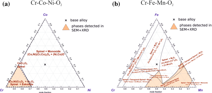
Stability diagrams for the formation of oxides on CrCoNi and CrMnFeCoNi at T = 800 °C, atmospheric pressure, and an O2-partial pressure of 0.02 atm. a Stability diagram for the Cr–Co–Ni–O2 system. To predict the formation of oxides on CrMnFeCoNi, the diagram of Cr–Fe–Mn–O2 is illustrated in b to focus on the metallic ions with the highest affinity with O
-
Below this oxide layer, a deep Mn-depleted zone is visible within the alloy.
-
A Cr-rich oxide layer formed at the alloy/oxide interface.

In both atmospheres, Mn-rich oxides are found at the oxide/gas interface and Cr-rich oxides at the oxide/alloy interface. The Mn-rich oxide scale consists of Mn3O4 for the O2- and Mn3O4 + α-Mn2O3 for the H2O-containing atmospheres. The Mn-oxide-chromia phase diagram suggests that at 800 °C, Mn3O4 and Mn2O3 may coexist [41]. However, in the present study, only the tetragonal Mn3O4 (hausmannite) was detected after oxidation in 2% O2 (see Fig. 4a). As the oxide scale is enriched in Mn, the underlying alloy matrix is correspondingly depleted in this element. In addition to Cr, Co, and Ni, a clear Fe enrichment was observed at the subsurface region of the alloy/oxide interface (see Figs. 8, 9). It might be possible that Fe is slightly dissolved at the oxide/alloy interface in the Mn3O4 layer. The tetragonal Mn3O4 phase (hausmannite) transforms above 1130 °C in air to the cubic spinel with the same stoichiometry. Generally, the Mn3O4 hausmannite is defect-rich and contains many vacant Mn-sites [42]. Fe2+/3+ has a similar ionic radius as Mn2+/3+ and can therefore easily occupy these free sites in the hausmannite type crystal structure, and the structure stays stable until 30% (atomic percent) of Fe. With higher Fe content, the tetragonal hausmannite becomes structurally unstable and transforms into a cubic spinel-type crystal structure [43]. In the present study, small amounts of Fe are likely present in Mn3O4. Furthermore, as shown later in Fig. 10b, taking thermodynamic boundary conditions into account (Co,Ni)(Fe,Cr)2O4 spinels are expected to be stable under the applied atmospheres. This spinel phase could be attributed to the Fe, Cr, Ni, and Co enrichment at the alloy/oxide interface.
CrCoNi
-
The dominating oxide phase forming on CrCoNi after exposure to both O2- and H2O-containing atmospheres is chromia (Cr2O3).
-
After exposure to 2% O2, chromia coexists with (Co,Ni)Cr2O4 spinels, while only a Cr2O3 layer was detected by XRD after exposure to 10% H2O. This latter chromia layer spalls off due to buckling after longer exposure times.
-
Below the outer chromia layer, a clear Cr-depleted zone is observed in the alloy. As a result, Co and Ni are correspondingly enriched.
Scale detachment and buckled regions are observed on the cross sections of the oxide layers grown on CrCoNi. The previously presented XRD pattern in Fig. 4b suggests that the oxide layer grown in 2% O2 (pO2 = 0.02 atm) consists of chromia (Cr2O3) and the (Ni, Co)Cr2O4 spinel. In the H2O-containing atmosphere (pO2 = 10−7 atm), pure Cr2O3 was observed by XRD, but it is worth recalling that spallation of the oxide scale occurred, see Fig. 4d, h. Therefore, the presence of other oxides cannot be excluded. The oxide layer after exposure to the O2-containing atmosphere was more continuous and denser compared to the layer formed in the H2O atmosphere.
The widths of the Cr-depleted zones within the matrix of CrCoNi are lower for the dry atmosphere compared to the humid atmosphere (see Fig. 7b, d) indicating that oxidation is more severe in the humid atmosphere. The oxide scale growing on CrCoNi in the humid atmosphere buckles and spalls off (see Figs. 4h, 7c), which in turn depletes further the alloy matrix in Cr and widens the diffusion-affected zone. Possible underlying mechanisms will be discussed in the section entitled Impact of the oxidizing atmosphere.
Thermodynamic Boundary Conditions
The phases identified by XRD in combination with SEM analyses are in good agreement with predictions made by thermodynamic calculations. Figure 10 displays the ternary stability diagrams calculated by Factsage 7.0 using the FactPS and Factoxid databases of the systems (a) Cr–Co–Ni–O2 and (b) Cr–Mn–Fe–O2 assuming an oxygen partial pressure pO2 of 0.02 atm corresponding to 2% O2. The diagrams present the equilibrium state of the mixture of the single elements (Cr, Co, Ni in Fig. 10a) with a constant oxygen (O2) partial pressure of pO2 = 0.02 atm. Depending on the alloy composition and activity of metals at the gas/alloy interface different oxides can form. The “X” mark at the center of the stability diagrams in Fig. 10 represents the compositions of the alloys considered in the present study. However, it must be remembered that the oxides forming on CrCoNi were found to be Cr-rich. Therefore, the relevant oxides are located in the Cr-rich corner of the stability diagram in Fig. 10a. The stable Cr-oxides growing on CrCoNi in 2% O2 are expected to be Cr2O3 and spinels of type (Co,Ni)Cr2O4 based on the stability diagram, see the orange triangle in Fig. 10a. These thermodynamic predictions are in excellent agreement with our experimental XRD patterns displayed in Fig. 4b. For the corrosion of CrCoNi in the 2% O2 environment, the initial reaction is:
The formation of a single chromia layer is not observed and probably a secondary reaction took place (II and III):
These reactions indicate that a higher amount of Cr compared to Ni and Co is necessary to form these oxides, and a wide Cr-depleted zone correspondingly forms in the base alloy, as detected by EDS (see Fig. 7). Moreover, Ni, Co, and Cr must diffuse toward the alloy/oxide interface, whereby Cr diffuses faster than Co and Ni [13].
In the 10% H2O environment, the oxygen partial pressure was calculated using the Reaction module of Factsage. This module considers all possible gas reactions at 800 °C. For these calculations, pure argon as carrier gas without additional oxygen contamination was considered. Changing the oxidizing atmosphere from 2% O2 to 10% H2O is equivalent to a reduction of the partial pressure of oxygen from 0.02 to 10−7 atm (ternary diagram not shown here). In this latter case, the stable phases are still Cr2O3 and a spinel with a mixed composition (Co,Ni)Cr2O4, but in the present study, only Cr2O3 was detected after exposure to 10% H2O. Oxidation times longer than 96 h may be required to observe the formation of spinels.
For CrMnFeCoNi, the Cr–Mn–Fe–O2 system should allow us to predict the stable phases forming on the CrMnFeCoNi HEA at the alloy/gas interface, since Cr, Mn, and Fe show the strongest affinity with oxygen. Simulating the thermodynamic boundary conditions and assuming a pO2 of 0.02 atm for CrMnFeCoNi, the activity of Ni and Co was constant and equal to 0.1. Experimentally, as the oxides were found to be mostly Mn-rich and to a lower extent slightly enriched in Cr. Such a region should be located in the lower right corner of the stability diagram in Fig. 10b. The stable oxides in contact with the 2% O2 atmosphere are expected to be (Co,Ni)(Fe, Cr)2O4 spinels, Mn3O4 (tetragonal hausmannite) and α-Mn2O3 (bixbyite). Experimentally, after oxidation in dry air only the Mn3O4 phase was detected using XRD and EDS. In contrast, the oxide layer consisting of Mn3O4 and α-Mn2O3 was observed after oxidation of CrMnFeCoNi in humid atmosphere. In both atmospheres, in the initial reaction, the oxidation of Mn proceeds according to:
or
The incoming oxygen reacts with the already grown Mn-oxide layer. This leads to further oxidation of Mn and the additional formation of α-Mn2O3 according to the following reaction:
These results are consistent with those reported by other authors [17, 20, 23] who observed the formation of an oxide layer consisting of multiple Mn-rich oxide phases after oxidation of CrMnFeCoNi in air and a CO2-containing atmosphere. The results of the present work show, that the oxidation products result from a combination of kinetic and thermodynamic aspects. The diagram in Fig. 11 displays the Gibbs free energy ∆G° as a function of temperature for different oxidation reactions taking place in the alloy-gas system studied here. The reactions are given for one mole of O2. Figure 11 demonstrates the preference for MnO formation followed by chromia, Mn3O4, and Mn2O3, while our experiments revealed the absence of MnO. As suggested by Kai et al. [19, 21], MnO may quickly oxidize to Mn3O4 and Mn2O3, which is the reason why it is not detected here. From a kinetic point of view, different groups [11, 13] showed that Mn diffuses by about one order of magnitude faster than Cr in the CrMnFeCoNi HEA. As a result, the flux of Mn atoms toward the gas/alloy interface during oxidation is much larger than the flux of Cr atoms and Mn-rich oxides form first. At a later stage, the matrix at the oxide/alloy interface becomes increasingly depleted in Mn and Cr-oxides then form below the Mn-oxides.

Diagram displaying the standard free energy ∆G° as a function of temperature for the oxidation of chromium and manganese. The reactions are given for one mole of oxygen
Impact of the Oxidizing Atmosphere
In the present study, two different oxidizing atmospheres were applied at 800 °C to analyze the oxidation behaviors of the CrMnFeCoNi HEA and the CrCoNi MEA. The observations by XRD and SEM as well as the applied oxygen partial pressures are summarized in Table 5. Obviously, the oxide layers of both alloys grown under a humid atmosphere are more discontinuous than the ones grown under 2% O2 and tend to spall off. The phenomenon of buckling, leading to spallation is especially pronounced for the CrCoNi. As demonstrated by the diffusion profiles of Cr in the CrCoNi matrix after 96 h of exposure (see Fig. 7), the length of the subsurface Cr-depleted zone is shorter for the 2% O2 atmosphere than for the 10% H2O atmosphere. The depletion zones are formed by the fast outward diffusion of Cr compared to Co and Ni diffusion [22] to form a chromia layer. This layer may set the pO2 at such a level that Ni and Co are not oxidized. The formed Cr2O3 layer is not protective and buckling is observed already after 48 h of exposure. Discontinuous chromia layers that show buckling and spallation have been observed for pure Cr [44, 45], FeCr [31, 46], and NiCr [32, 47] binary alloys as well as engineering Cr2O3-forming alloys [24, 25, 46, 48]. Buckling is mainly caused by mechanical stresses that are related to two main origins. The first one is related to the mismatch between the volume of the unit cell of the oxide layer and that of the alloy during isothermal growth. The Pilling–Bedworth ratio (RPB) can be calculated using [48]:
where \(M_{{{\text{Cr}}_{2} {\text{O}}_{3} }}\) = 151.99 g/mol and \(M_{\text{CrCoNi}}\) = 56.54 g/mol are the molar masses of chromia and the CrCoNi MEA, respectively, and their densities are \(\rho_{{{\text{Cr}}_{2} {\text{O}}_{3} }}\) = 5.2 g/cm3 and \(\rho_{\text{CrCoNi}}\) = 8.2 g/cm3 [49]. In Eq. (2), n = 2 represents the number of atoms of metal per molecule of the oxide. Using the above-mentioned inputs, Eq. (2) yields an RPB value of 2.11 similar to that of pure Cr (2.05) [50]. As the oxide occupies a significantly larger volume than the MEA on which it grows, compression stresses accumulate in the oxide scale during its growth leading to buckling and ultimately to spallation. A second reason for the occurrence of internal stresses in the oxide scale is the large mismatch between the thermal expansion coefficients of the oxides and the alloy, leading to buckling and spallation upon cooling. The thermal expansion coefficients of (Co,Ni)Cr2O4 and chromia at 800 °C are αL ~ 7.4 × 10⁻⁶ K−1 [51] and αL ~ 8.5 × 10⁻⁶ K−1 [52], respectively, and are about two times lower than for CrCoNi (16.4 × 10⁻⁶ K−1 at 800 °C) [49]. This mismatch in coefficients of thermal expansion between the oxide and the alloy substrate leads to the accumulation of compression stresses in the oxide scale and tensile stresses in the alloy matrix. This further promotes buckling and spallation during cooling from service to room temperature, which may lead to scale detachment [46].
At this point, it is worth recalling that the oxide layers grown in 2% O2 and 10% H2O contain voids, pores and showed evidence of scale detachment. These features are characteristics of a weak oxide/alloy interface and are more pronounced for the CrCoNi after 10% H2O exposure (see Fig. 12). As explained in detail by Evans et al. [53], such weak interfaces induce buckling, enhanced tensile stresses develop at the perimeter of the buckled regions and lead to spallation of the oxide layer.

SEM–BSE image of CrCoNi after 96 h exposure to 10% H2O at 800 °C. a Surface and b cross-sectional morphology of the oxide layers on CrCoNi
The voids and the scale detachment observed in Fig. 12 may also affect oxide-scale spallation in the CrCoNi MEA exposed to humid atmosphere. These microstructural features can act as crack initiation sites, leading to scale failure. Usually, this process produces a fracture surface nearly perpendicular to the metal/oxide. The surface and cross-sectional morphology (see Figs. 4h, 5a, and 12a) are similar to the observations shown by Zhang et al. [54], who studied spallation of protective chromia on Ni30Cr after exposure for 2–20 h at 1000 °C in pure oxygen.
The following question now arises, why buckling and spallation of the oxide layer were especially observed after oxidation in humid atmosphere? To answer this question, different scenarios might be considered. First, as reported by Yuan et al. [55], the oxide-scale spallation may be related to its hydrogen permeation. The authors investigated the failure mechanism of chromia scales grown on HR3C (austenitic steel containing 25% by weight Cr) at 700 °C in pure steam for up to ~ 300 h exposure time. After 50 h, a thin chromia layer was formed, which showed buckling and cracking. At the spalled area, a significant number of pores was present. The authors concluded that the spallation of the oxide proceeds during cooling and assumed a dissociation reaction of water molecules at the specimen surface leading to the formation of OH− and H+ ions, which may further react with the alloy. These dissociation products according to equation VIII (which will be introduced later) may diffuse into the oxide and to the bulk material. During the ongoing corrosion process, the pores at the alloy interface could act as a hydrogen trap, for re-reacted hydrogen. The hydrogen would increase the pressure in the pores and the chromia layer could not withstand these additional stresses resulting in buckling and cracking. Details about the proposed mechanism can be found in Ref. [55]. Voids and/or agglomeration of pores are observed at the CrCoNi alloy/oxide interface after exposure to the humid atmosphere (see Fig. 12b) which is consistent with the scenario proposed by Yuan et al. [55]. If the Cr concentration at the subscale region is sufficient, healing and the growth of a secondary chromia layer might be observed. Such a healing effect could be associated with the secondary chromia layer below the buckled oxide as shown in Fig. 12b.
Another scenario may be considered in view of the layer structure and stacking of the chromia layers grown on CrCoNi in the humid atmosphere. In Figs. 5a and 12b, the above-mentioned secondary thin chromia layer was frequently observed below the buckled chromia layer together with a rough interface. This layer may correspond to an internal chromia layer. Galerie et al. [44] showed that a single chromia layer was formed on pure Cr in oxygen at 900 °C, while a duplex scale was observed in the presence of water vapor. A further spallation investigation by Latu-Romain et al. [45] focused on the oxidation of pure Cr at 900 °C in a low-pO2 atmosphere (~ 10−12 atm). The authors identified the formation of duplex chromia layers with different microstructures, semiconducting, and transport properties. Some voids of a few hundreds of nanometers were observed in the internal subscale at the oxide/alloy interface. The authors proposed that the spallation and delamination of the scale did not occur at the interface between the two chromia layers but at the metal/oxide interface. In the present study, the location of the original sample surface was not marked and it is therefore not possible to prove or disprove whether a duplex scale formed on CrCoNi during oxidation. Nevertheless, for both scenarios, stress accumulation in the scale probably leads to buckling during isothermal exposure and the spallation occurs during sample cooling. We think that this constitutes the most likely reason for the spallation of chromia layers grown on CrCoNi.
In summary, the oxidation process for CrCoNi in humid atmosphere can be divided into different steps:
-
1.
The water molecules (H2O) react with Cr from the CrCoNi matrix and form a thin chromia layer that may result from two possible reactions VII and VIII
$$\begin{aligned} 2 {\text{Cr}} + 3 {\text{H}}_{ 2} {\text{O}} \to {\text{Cr}}_{ 2} {\text{O}}_{ 3} + 6 {\text{H}}^{ + } \left( {{\text{after}}\;{\text{Hultquist}}\;{\text{et}}\;{\text{al}}.\;\left[ { 5 6} \right]} \right).\end{aligned}$$(VII)$$\begin{aligned} 2 {\text{H}}_{ 2} {\text{O}} \to {\text{O}}_{ 2} + 4 {\text{H}}^{ + } \;{\text{followed}}\;{\text{by}}\; 4 {\text{Cr}} + 3 {\text{O}}_{ 2} \to 2 {\text{Cr}}_{ 2} {\text{O}}_{ 3}. \end{aligned}$$(VIII) -
2.
The reactions VII and VIII are driven by the chemical potential and cause Cr depletion in the alloy, due to Cr-transport toward the alloy/oxide interface.
-
3.
The subscale area of the alloy is depleted in Cr, and with further oxidation, the Cr supply for dense layer growth of chromia is not sufficient.
-
4.
Buckling occurs at the weak interfaces, followed by spallation during cooling.
The Cr2O3 layer is not dense and H2O continues to react with Cr2O3. Especially in mixed gas environments (for instance O2 + H2O), it is known that the reaction of Cr2O3 with O2 and H2O leads to further volatilization of chromia by the formation of CrO2(OH)2 according to reaction IX [31, 33, 57]
The volatilization rate is also reported to be enhanced when the chromia layer is porous [58]. However, in the low-pO2 humid atmosphere, it was reported for Fe10Cr and Fe20Cr exposed to Ar—7% H2O at 900 °C for 72 h that the formation of volatile Cr-oxy-hydroxide is not the main reason for the suppression of a protective chromia scale growth [31]. The vapor pressure of volatile oxy-hydroxide increases with increasing pO2 and/or pH2O. The present study applied a low-pO2 (10−7 atm) humid atmosphere and the equilibrium oxygen partial pressure is too low to substantially contribute to the destruction of the chromia scale. This was previously reported by Quadakkers et al. [31] who demonstrated that the equilibrium oxygen partial pressure of 10−6 atm in Ar—7% H2O is 5–6 orders of magnitude smaller than in Ar—20% O2—7% H2O atmosphere and thus does not support the volatilization of chromia observed in the present study. Therefore, we assume that hydrogen-induced enhanced internal oxidation, as proposed by Quadakkers et al. [31] and supported by the study from Yuan et al. [55], is responsible for the occurrence of breakaway oxidation when CrCoNi is exposed to a humid atmosphere.
The aspects discussed above demonstrate, that in the H2O-containing atmosphere, the high Cr-containing CrCoNi MEA does not provide sufficient oxidation protection for long term applications since several chromia destroying mechanisms might occur. For now, no conclusion about the mechanism can be reached, but this issue is currently under investigation.
Concluding Remarks
The oxidation behaviors of the equiatomic CrMnFeCoNi HEA and the equiatomic CrCoNi MEA were studied by isothermal exposure experiments in 2% O2 and 10% H2O at 800 °C for times up to 96 h. CrMnFeCoNi showed a poor oxidation resistance in both atmospheres due to the fast growth of porous Mn-rich oxide layers. In the O2-containing atmosphere, the oxide layer consists only of Mn3O4, while Mn3O4 and α-Mn2O3 were identified in the oxide scale growing on CrMnFeCoNi when exposed to a humid atmosphere. The CrCoNi MEA developed Cr2O3 layers in both atmospheres. For the O2-containing atmosphere, the chromia layer additionally contained a secondary spinel phase of type (Co,Ni)Cr2O4. These observations are in good agreement with considerations of the thermodynamic boundary conditions. In the H2O-containing atmosphere, buckling and spallation of the chromia layer were observed. The buckling process can be understood as a multi-step process leading to a weak oxide/alloy interface that promotes buckling and spallation. Since the chromia layer is porous and discontinuous in a humid atmosphere, the volatilization of chromia must also be considered for applications at high oxygen partial pressures. From these results, it can be concluded that the CrCoNi MEA can only be employed at high temperatures when only minor amounts of H2O are present in the service environment.
References
J. W. Yeh, S. K. Chen, S. J. Lin, et al., Advanced Engineering Materials 6, 299–303 (2004).
J. W. Yeh, Y. L. Chen, S. J. Lin and S. K. Chen, Materials Science Forum 560, 1–9 (2007).
B. Cantor, I. T. H. Chang, P. Knight and A. J. B. Vincent, Materials Science and Engineering: A 375, 213–218 (2004).
A. Gali and E. P. George, Intermetallics 39, 74–78 (2013).
B. Gludovatz, A. Hohenwarter, D. Catoor, E. H. Chang, E. P. George and R. O. Ritchie, Science 345, 1153 (2014).
Z. Wu, H. Bei, G. M. Pharr and E. P. George, Acta Materialia 81, 428–441 (2014).
G. Laplanche, J. Bonneville, C. Varvenne, W. A. Curtin and E. P. George, Acta Materialia 143, 257–264 (2018).
F. Otto, G. M. Pharr and E. P. George, Intermetallics 46, 131–140 (2014).
M. Schneider, E. P. George, T. J. Manescau, et al., International Journal of Plasticity 124, 155–169 (2020).
G. Laplanche, M. Schneider, F. Scholz, J. Frenzel, G. Eggeler and J. Schreuer, Scripta Materialia 177, 44–48 (2020).
K. Y. Tsai, M. H. Tsai and J. W. Yeh, Acta Materialia 61, 4887–4897 (2013).
J. Y. He, C. Zhu, D. Q. Zhou, W. H. Liu, T. G. Nieh and Z. P. Lu, Intermetallics 55, 9–14 (2014).
M. Vaidya, K. G. Pradeep, B. S. Murty, G. Wilde and S. V. Divinski, Acta Materialia 146, 211–224 (2018).
G. Laplanche, Acta Materialia 199, 193–208 (2020).
D. Xie, R. Feng, P. K. Liaw, H. B. Bei and Y. F. Gao, Intermetallics 121, 106775 (2020).
Y. B. Kang, S. H. Shim, K. H. Lee and S. I. Hong, Materials Research Letters 6, 689–695 (2018).
G. Laplanche, U. F. Volkert, G. Eggeler and E. P. George, Oxidation of Metals 85, 629–645 (2016).
W. Kai, W. L. Jang, R. T. Huang, C. C. Lee, H. H. Hsieh and C. F. Du, Oxidation of Metals 63, 169–192 (2005).
W. Kai, C. C. Li, F. P. Cheng, et al., Corrosion Science 121, 116–125 (2017).
W. Kai, F. C. Chien, F. P. Cheng, R. T. Huang, J. J. Kai and C. T. Liu, Corrosion Science 153, 150–161 (2019).
W. Kai, C. C. Li, F. P. Cheng, et al., Corrosion Science 108, 209–214 (2016).
N. K. Adomako, J. H. Kim and Y. T. Hyun, Journal of Thermal Analysis and Calorimetry 133, 13–26 (2018).
G. R. Holcomb, J. Tylczak and C. Carney, JOM 67, 2326–2339 (2015).
P. Kofstad, High Temperature Corrosion, (Elsevier, Amsterdam, 1988).
D. J. Young, in High Temperature Oxidation and Corrosion of Metals, 2nd ed, ed. D. J. Young (Elsevier, Amsterdam, 2016), pp. 549–601.
D. J. Young and B. A. Pint, Oxidation of Metals 66, 137–153 (2006).
H. C. Graham and H. H. Davis, Journal of the American Ceramic Society 54, 89–93 (1971).
C. S. Tedmon, Journal of the Electrochemical Society 113, 766–768 (1966).
B. A. Pint, R. Peraldi and P. J. Maziasz, High Temperature Corrosion and Protection of Materials 6, Prt 1 and 2, Proceedings 461–464, 815–822 (2004).
C. F. McDonald, Applied Thermal Engineering 23, 1463–1487 (2003).
W. J. Quadakkers, J. Żurek and M. Hänsel, JOM 61, 44–50 (2009).
J. Zurek, D. J. Young, E. Essuman, et al., Materials Science and Engineering: A 477, 259–270 (2008).
T. Perez, L. Latu-Romain, R. Podor, et al., Oxidation of Metals 89, 781–795 (2018).
G. Laplanche, S. Berglund, C. Reinhart, A. Kostka, F. Fox and E. P. George, Acta Materialia 161, 338–351 (2018).
GzFa. I. Gesellschaft zur Förderung angewandter Informatik [Society for the Promotion of Applied Computer Science] B. Layers Version 1.71 (2012).
K. Nutzmann, A. Kranzmann and C. Stephan-Scherb, Materials at High Temperatures 35, 558–568 (2018).
G. Laplanche, A. Kostka, C. Reinhart, J. Hunfeld, G. Eggeler and E. P. George, Acta Materialia 128, 292–303 (2017).
K. Chandra, A. Kranzmann, R. S. Neumann, G. Oder and F. Rizzo, Oxidation of Metals 83, 291–316 (2015).
M. P. Agustianingrum, U. Lee and N. Park, Corrosion Science 173, 108755 (2020).
A. L. Marasco and D. J. Young, Oxidation of Metals 36, 157–174 (1991).
D. H. Speidel and A. Muan, Journal of the American Ceramic Society 46, 577–578 (1963).
F. C. M. Driessens, Inorganica Chimica Acta 1, 193–201 (1967).
S. K. Sahu, B. Y. Huang, K. Lilova, B. F. Woodfield and A. Navrotsky, Physical Chemistry Chemical Physics 17, 22286–22295 (2015).
A. Galerie, Y. Wouters and M. Caillet, Materials Science Forum 369–372, 231–238 (2001).
L. Latu-Romain, Y. Parsa, S. Mathieu, M. Vilasi and Y. Wouters, Oxidation of Metals 90, 255–266 (2018).
I. G. Wright, M. Schutze, P. F. Tortorelli and R. B. Dooley, Materials at High Temperatures 24, 265–274 (2007).
Y. Xie, J. Q. Zhang and D. J. Young, Oxidation of Metals 94, 219–233 (2020).
D. R. Askeland, P. P. Fulay and W. J. Wright, The Science and Engineering of Materials, (Cengage Learning, Stamford, 2006).
G. Laplanche, P. Gadaud, C. Bärsch, et al., Journal of Alloys and Compounds 746, 244–255 (2018).
H. J. Maier, T. Niendorf and R. Bürgel, Handbuch Hochtemperatur-Werkstofftechnik: Grundlagen, Werkstoffbeanspruchungen, Hochtemperaturlegierungen und -beschichtungen, (Vieweg+Teubner, Wiesbaden, 2015).
A. Petric and H. Ling, Journal of the American Ceramic Society 90, 1515–1520 (2007).
J. Robertson and M. I. Manning, Materials Science and Technology 6, 81–92 (1990).
H. E. Evans, Materials Science and Engineering: A 120–121, 139–146 (1989).
Y. F. Zhang and D. A. Shores, Oxidation of Metals 40, 529–553 (1993).
J. Yuan, W. Wang, H. Zhang, L. Zhu, S. Zhu and F. Wang, Corrosion Science 109, 36–42 (2016).
G. Hultquist, B. Tveten, E. Hornlund, M. Limback and R. Haugsrud, Oxidation of Metals 56, 313–346 (2001).
B. Pujilaksono, T. Jonsson, M. Halvarsson, I. Panas, J. E. Svensson and L. G. Johansson, Oxidation of Metals 70, 163–188 (2008).
A. Stenzel, D. Fahsing, M. Schutze and M. C. Galetz, Materials and Corrosion 70, 1426–1438 (2019).
Acknowledgements
The authors gratefully acknowledge Heike Nitschke and Romeo Saliwan Neumann for the metallographic work and the extensive SEM–EDS analysis. Guillaume Laplanche acknowledges funding from the German Research Foundation (Deutsche Forschungsgemeinschaft DFG) through the Priority Program SPP 2006 “Compositionally Complex Alloys—High Entropy Alloys” Project LA 3607/3-2.
Funding
Open Access funding enabled and organized by Projekt DEAL.
Author information
Authors and Affiliations
Contributions
All authors contributed to the study conception and design. Material preparation, data collection, and analysis were performed by WS, GL, MS, SK, and CS-S. The manuscript was written by CS-S, and all authors commented on previous versions of the manuscript. All authors read and approved the final manuscript.
Corresponding author
Additional information
Publisher's Note
Springer Nature remains neutral with regard to jurisdictional claims in published maps and institutional affiliations.
Rights and permissions
Open Access This article is licensed under a Creative Commons Attribution 4.0 International License, which permits use, sharing, adaptation, distribution and reproduction in any medium or format, as long as you give appropriate credit to the original author(s) and the source, provide a link to the Creative Commons licence, and indicate if changes were made. The images or other third party material in this article are included in the article's Creative Commons licence, unless indicated otherwise in a credit line to the material. If material is not included in the article's Creative Commons licence and your intended use is not permitted by statutory regulation or exceeds the permitted use, you will need to obtain permission directly from the copyright holder. To view a copy of this licence, visit http://creativecommons.org/licenses/by/4.0/.
About this article

Cite this article
Stephan-Scherb, C., Schulz, W., Schneider, M. et al. High-Temperature Oxidation in Dry and Humid Atmospheres of the Equiatomic CrMnFeCoNi and CrCoNi High- and Medium-Entropy Alloys. Oxid Met 95, 105–133 (2021). https://doi.org/10.1007/s11085-020-10014-7
Received:
Revised:
Accepted:
Published:
Issue Date:
DOI: https://doi.org/10.1007/s11085-020-10014-7