
Abstract
With the exceptions of Synchrotron Radiation sources, beams of accelerated particles are generally designed to interact either with one another (in the case of colliders) or with a specific target (for the operation of Fixed Target experiments, the production of secondary beams and for medical applications). However, in addition to the desired interactions there are unwanted interactions of the high energy particles which can produce undesirable side effects. These interactions can arise from the unavoidable presence of residual gas in the accelerator vacuum chamber, or from the impact of particles lost from the beam on aperture limits around the accelerator, as well as the final beam dump. The wanted collisions of the beams in a collider to produce potentially interesting High Energy Physics events also reduces the density of the circulating beam and can produce high fluxes of secondary particles.
You have full access to this open access chapter, Download chapter PDF
With the exceptions of Synchrotron Radiation sources, beams of accelerated particles are generally designed to interact either with one another (in the case of colliders) or with a specific target (for the operation of Fixed Target experiments, the production of secondary beams and for medical applications). However, in addition to the desired interactions there are unwanted interactions of the high energy particles which can produce undesirable side effects. These interactions can arise from the unavoidable presence of residual gas in the accelerator vacuum chamber, or from the impact of particles lost from the beam on aperture limits around the accelerator, as well as the final beam dump. The wanted collisions of the beams in a collider to produce potentially interesting High Energy Physics events also reduces the density of the circulating beam and can produce high fluxes of secondary particles.
All of these unwanted interactions affect the performance of an accelerator, in desorption of gas from the vacuum system, in reduced lifetime of the circulating beam, in reduction of the collider luminosity and in background for the detectors. In this chapter the basic physical phenomena of particle interactions with matter are described, together with the techniques used to simulate the interaction with matter. The different types of particle interactions with the surroundings are elaborated in the context of their adverse effects on the accelerator performance and the mitigation measures. A full description of the effects and mitigation measures associated with the vacuum systems of accelerators is given separately in Chap. 8.
5.1 The Interactions of High Energy Particles with Matter
Modern accelerators use leptons or hadrons (including ions) and have beam energies spanning the MeV to TeV range. Therefore, the capability of modelling particle interactions and showers from these energy ranges down to thermal energies is essential during all stages of the lifetime cycle of an accelerator, from the accelerator design through operation to its final decommissioning.
Before briefly discussing general aspects of hadronic and electromagnetic showers, a short overview is given of important ingredients for accelerator applications:
-
energy deposition for the design of accelerator components and elements (e.g., collimators, magnets);
-
particle fluences as a function of energy, angle and position (e.g., detector or radiation damage and radiation to electronics studies);
-
distribution of particle interactions, inelastic interaction density (e.g., for tracking and loss pattern studies);
-
residual nuclei production and generation of radioactive isotopes by beam interactions (e.g., radiation protection aspects like air activation or equipment handling).
To allow for calculations of related quantities, the underlying physical processes must not only be well understood and described in models, but also included in calculation codes able to yield allow reliable estimates within a reasonable time.
5.1.1 Basic Physical Processes in Radiation Transport Through Matter
Hadron and electromagnetic showers are very complex phenomena, whose description in terms of basic physical interactions requires a detailed and complex modelling.
As soon as the energy of a primary hadron beam exceeds a few tens of MeV, inelastic interactions start playing a major role and generate secondary particles that will have enough energy to trigger further interactions giving rise to hadronic showers. Furthermore, whenever the beam energy is high enough that significant pion production can occur, an increasing fraction of the energy will be transferred from the hadronic to the electromagnetic part due to meson decay (e.g., π 0 decaying into a gamma pair). The pion production threshold for nucleons interacting with stationary nucleons is around 290 MeV.
Therefore, energetic hadronic showers are always accompanied by significant electromagnetic showers, where the latter ones tend to develop independently without further hadronic particle production (with the exception of electro- and photo-nuclear interactions of lower importance for hadron accelerators, which however have to be considered for lepton accelerators).
While electromagnetic interactions can be described in one coherent theory (QED), the same does not apply to hadronic nuclear interactions.
The development of hadron initiated showers is determined both by atomic processes (e.g. ionization, multiple Coulomb Scattering, etc.), which take place very frequently, as well as relatively rare nuclear interactions (both elastic and nonelastic). Electromagnetic showers are determined by the same atomic processes plus additional ones (e.g., Bremsstrahlung, pair production, Compton scattering, etc.) which are specific for electrons, positrons or photons. Nuclear interactions coming from the electromagnetic component usually play a minor role, and whenever the interest is not in the small fraction of hadrons produced by electromagnetic particles they can be safely neglected.
Concerning particle production, energetic (shower) particles are concentrated mainly around the primary beam axis, regardless of their identity. Their ionization as well as the electromagnetic cascades define the core of the energy deposition distribution. At the same time, neutrons (since these are the only neutral hadrons with a long enough lifetime) will dominate at energies where charged particle ranges become shorter than the respective interaction length. In this sense, the energy deposition associated with low energy neutron interactions constitute the peripheral tails of the energy deposition distribution. Most of the interactions are due to particles (mainly neutrons) of moderate energy.
Pions can be only produced by shower particle interactions, so that they are often considered as the real indicator of a high energy cascade. Neutrons, and to a lesser extent protons, are copiously produced also in the final stages of nuclear interactions (e.g., evaporation) down to projectile energies that are comparable to their nuclear binding energy.
As previously mentioned, to focus on the relevant processes one usually distinguishes between continuous and discrete (or explicit) processes. This distinction reflects a real physical distinction, between processes which occur very frequently with mean free paths much shorter than particle ranges in matter, and others that, however, are often the dominating ones in determining the shower development.
The most important discrete processes are:
-
inelastic nuclear interaction;
-
decay;
-
elastic nuclear interaction;
-
delta-ray production;
-
bremsstrahlung;
-
annihilation;
-
photoelectric effect;
-
Compton scattering;
-
pair production;
-
coherent (Rayleigh) scattering.
In addition to these processes, nuclear interactions with a much lower rate can occur also for photons (as well as with a reduced rate of about 1/137 for electrons and positrons). Bremsstrahlung radiation can also be produced by “heavy” charged particles even though it is significantly suppressed. Furthermore, charged particles (light and heavy ones) can produce electron-positron pairs.
5.1.2 Simulation Tools
In all life cycle stages of an accelerator the use of simulation, notably Monte-Carlo codes, became fundamental. Thanks to the variety of such codes over different particle physics applications and the associated extensive benchmarking with experimental data, the modelling has reached an unprecedented accuracy. Furthermore, most codes allow the user to simulate all aspects of a high energy particle cascade in one and the same run: from the first interaction over the transport and re-interactions (hadronic and electromagnetic) of the produced secondaries, to detailed nuclear fragmentation, the calculation of radioactive decays and even of the electromagnetic shower from such delayed decays.
In the following we give a brief overview of the most used multi-purpose codes around accelerator applications.
5.1.2.1 FLUKA
FLUKA is a general-purpose particle interaction and transport code with roots in radiation protection and respective design and detector studies for high energy accelerators [1, 2]. It comprises all features needed in this area of application, such as detailed nuclear interaction models, full coupling between hadronic and electromagnetic processes and numerous variance reduction options.
The module for hadronic interactions is called PEANUT and consists of a phenomenological description (Dual Parton Model-based Glauber Gribov cascade) of high energy interactions, through a generalized intranuclear cascade, pre-equilibrium emissions as well as evaporation, fragmentation, fission and de-excitation by gamma emission. Interactions of ions are simulated through interfaces with different codes depending on the energy range (DPMJET3 above 5 GeV/n and rQMD-2.4 between 0.125 and 5 GeV/n, while the embedded Boltzmann Master Equation model is applied below 0.125 GeV/n).
The transport of neutrons with energies below 20 MeV is performed by a multi-group algorithm based on evaluated cross section data (ENDF/B, JEFF, JENDL etc.) binned into 260 energy groups, 31 of which in the thermal region. For a few isotopes point-wise cross sections can be optionally used. The detailed implementation of electromagnetic processes in the energy range between 1 keV and 1 PeV is fully coupled with the models for hadronic interactions.
5.1.2.2 GEANT4
GEANT4 is an object-oriented toolkit originally designed to simulate detector responses of modern particle and nuclear physics experiments [3, 4]. It consists of a kernel which provides the framework for particle transport, including tracking, geometry description, material specifications, management of events and interfaces to external graphics systems.
The kernel also provides interfaces to physics processes. In this regard the flexibility of GEANT4 is unique as it allows the user to select freely the physics models which serve best the particular application needs. This freedom comes with high responsibility as the user must ensure that the most adequate models are used for a given problem. Implementations of interaction models exist over an extended range of energies, from optical photons and thermal neutrons to high energy interactions as required for the simulation of accelerator and cosmic ray experiments. In many cases complementary or alternative modelling approaches are offered from which the user can choose.
Descriptions of intranuclear cascades include implementations of the Binary and the Bertini cascade models (the latter significantly reworked and not at all linked to the original Bertini model). Both are valid for interactions of nucleons and charged mesons, the former for energies below 3 GeV and the latter below 10 GeV. The Intranuclear Cascade of Liège (INCL) is also an usable option. At higher energies (up to 10 TeV), three models are available: a high-energy parameterized model (using fits to experimental data), a quark-gluon string model and the Fritiof fragmentation model, both based on string excitations and decay into hadrons. Nuclear de-excitation models include abrasion-ablation and Fermi-breakup models. Furthermore, heavy ion interactions can also be simulated if the appropriate packages are linked.
The package for electromagnetic physics comprises the standard physics processes as well as extensions to energies below 1 keV, including emissions of X-rays, optical photon transport, etc.
5.1.2.3 MARS15
The MARS15 code system [5, 6] is a set of Monte Carlo programs for the simulation of hadronic and electromagnetic cascades which is used for shielding, accelerator design and detector studies. Correspondingly, it covers a wide energy range: 100 keV–100 TeV for muons, charged hadrons and heavy ions, 1 keV–100 TeV for electromagnetic showers and down to 0.00215 eV for neutrons.
Hadronic interactions above 5 GeV can be simulated with either an inclusive or an exclusive event generator. While the former is CPU-efficient (especially at high energy) and based on a wealth of experimental data on inclusive interaction spectra, the latter provides final states on a single interaction level and preserves correlations. In the exclusive mode, the cascade-exciton model code CEM03, the Quark-Gluon String Model code LAQGSM03 and the DPMJET3 code are implemented, including models for a detailed calculation of nuclide production via evaporation, fission and fragmentation processes.
Interfaced to MARS, the MCNP4C code handles all interactions of neutrons with energies below 14 MeV. Produced secondaries other than neutrons are directed back to the MARS15 modules for further transport.
5.1.2.4 MCNP
MCNP6 [7] originates from the Monte Carlo N-Particle transport (MCNP)-family of neutron interaction and transport codes and, therefore, features one of the most comprehensive and detailed description of the related physical processes. The extension to other particle types, including ions and electromagnetic particles, allowed an expansion of the areas of application from purely neutronics to, among others, accelerator shielding design, medical physics and space radiation.
The neutron interaction and transport modules use standard evaluated data libraries mixed with physics models where such libraries are not available. The transport is continuous in energy and includes all features necessary for reactor simulations, including burn-up, depletion and transmutation. Different generalized intranuclear cascade codes can be linked to explore different physics implementations, such as CEM03, INCL4 and ISABEL. They either contain fission-evaporation models or can be coupled to such models (i.e., ABLA) allowing detailed predictions for radio-nuclide production. While the intranuclear cascade codes are limited to interaction energies below a few GeV, a link to the Quark-Gluon String Model code LAQGSM03 extends this energy range to about 800 GeV. The latter code also allows the simulation of ion interactions.
5.1.2.5 PHITS
The Particle and Heavy-Ion Transport code System PHITS (see [8] and [9] and references therein) was among the first general-purpose codes to simulate the transport and interactions of heavy ions in a wide energy range, from 10 MeV/nucleon to 100 GeV/nucleon. It is based on the high-energy hadron transport code NMTC/JAM which was extended to heavy ions by incorporating the JAERI Quantum Molecular Dynamics code JQMD.
Below energies of a few GeV hadron-nucleus interactions in PHITS are described through the production and decay of resonances while at higher energies (up to 200 GeV) inelastic hadron-nucleus collisions proceed via the formation and decay of so-called strings which eventually hadronize through the creation of (di)quark-anti(di)quark pairs. Both are embedded into an intranuclear cascade calculation. Nucleus-nucleus interactions are simulated, within a molecular dynamics framework, based on effective interactions between the two self-binding system of nucleons.
The generalized evaporation model GEM treats the fragmentation and de-excitation of the spectator nuclei and includes 66 different ejectiles (up to Mg) as well as fission processes. The production of radioactive nuclides, both from projectile and target nuclei, thus follows directly from the microscopic interaction models.
The transport of low energy neutrons employs cross sections from evaluated nuclear data libraries such as JENDL below 20 MeV. Electromagnetic interactions are simulated based on the EGS5 code in the energy range between 1 keV and 1 TeV.
Due to its capability to transport nuclei PHITS is frequently applied in ion-therapy and space radiation studies. The code is also used for general radiation transport simulations, such as in the design of spallation neutron sources.
5.1.2.6 Simulation Uncertainties
Depending on the complexity of Monte-Carlo simulations, the size of geometries and the energy range involved, calculations can carry considerable uncertainties of various sources which are in many cases difficult to evaluate. While statistical uncertainties are generally below a few percent thanks to the available computing power, systematic errors are in most cases very difficult, or even impossible, to predict in an accurate way.
The main sources of error are:
-
Error due to the physics modelling: e.g., in the uncertainty in cross sections, especially at modern accelerators operating at very high energies or applications sensitive to other uncertainties in the modelling used in the simulation code. One can usually expect up to few 10% uncertainty on integral quantities, while for multi differential quantities the uncertainty can be much worse.
-
Further uncertainties due to the assumptions used in the description of the geometry and of the materials under study. Usually it is difficult to quantify this uncertainty and experience shows that a factor of 2 can be taken as a safe limit for general calculations. For special cases, even in case of rather complex geometries, but when the design is implemented to a very detailed level, the latter can be reduced to about 10–20%, but rarely significantly below.
-
Typical for accelerator applications, additional errors appear when having beams grazing at small angles to surfaces, where either the surface roughness is not taken into account, small misalignments can have large effects, or where one is interested in scattering effects over large distances. Therefore, especially for the latter, a safety factor of 2–3 has to be considered.
Only a detailed case-by-case analysis and careful evaluation with monitoring data can reduce the above to very low levels. Such studies are continuously done by code developers, as well as core code users and nicely show the possible high-accuracy reached with modern Monte-Carlo codes (see for instance [10]).
5.1.3 Practical Shielding Considerations
In most of the cases around high-energy hadron accelerator operation, the particle cascades originate from beam interactions due to four basic source terms:
-
beam–beam interactions (at and close to the experiments);
-
beam–residual gas interactions (all along the accelerator);
-
direct losses: beam cleaning at collimator locations or beam dump;
-
spurious losses (random locations around the accelerator).
The emerging secondary particle cascade is then again defining a multi particle-type and energy spectrum, interacting with the various materials around the accelerator. Therefore, in order to reduce the radiation levels and the corresponding fluences, shielding material can be employed to initiate and absorb showers. If the shielding material is thick, the cascades continue until most of the charged particles and photons have been absorbed, except for neutrons and secondary photons.
The following aspects have to be considered in the shielding conceptual design:
5.1.3.1 Radiation Attenuation
The propagation of high-energy hadrons features an exponential decrease due to nuclear reactions, while their energy loss, in case they are charged, is mostly due to ionization. The latter accounts for the majority of the energy loss in electromagnetic showers and for about 2/3 of the energy deposited in hadronic showers. Most of the other 1/3 of the hadronic energy is carried away by neutrons. Being neutral these are not affected by ionization losses, are decoupled from the rest of the shower, are subject to elastic and inelastic collisions and are considerably more penetrating than the charged component. Hadronic showers above 100 MeV progress through a variety of hadronic and nuclear processes that result in secondaries that are predominantly pions (π +, π −,π 0), followed in importance by nucleons (protons, neutrons), strange mesons/baryons and photons. The π 0 component, appearing whenever hadron energies are above the pion production threshold, is particularly important, since it decays immediately to two photons producing electromagnetic showers and shifting the shower energy from the hadronic to the electromagnetic sector. Hadrons above few tens of MeV undergo nuclear reactions that increase the neutron multiplicity. The spallation process breaks the nucleus into a few large fragments. Additional neutrons may also be produced just during this process, as well as by the subsequent evaporation from these excited fragments.
Since the fragments have large mass (M) and total charge (Z) and ionize, they will be stopped quickly in dense shield materials.
5.1.3.2 Shielding of Electromagnetic Showers
As mentioned earlier, electromagnetic showers in the multi-GeV range develop through successive bremsstrahlung and pair production. The particles involved are photons, electrons and positrons that in dense materials have typical radiation lengths in the centimeter range. As a result, high-energy electromagnetic showers are halted by a typical concrete shielding wall having thickness of the order of 1 m or by a tungsten layer of a few centimeters. It has to be noted that secondary neutrons are also generated through photo-production, thus associated shielding issues have to be correctly considered.
5.1.3.3 Shielding of Neutrons
The elastic scattering cross section of neutrons on nuclei is large at all energies and has a role in attenuating them. The scattered neutron will lose energy on every elastic collision, especially if the target nucleus is light and so carries away a larger fraction of the energy as it recoils. Therefore, the presence of hydrogen is most effective in reducing the neutron kinetic energy. Special care must be taken with respect to:
-
neutrons streaming through ventilation channels or other penetrations, where intermediate and low-energy neutrons readily scatter from the wall. Propagation down the channel is thus possible via a series of ‘reflections’ even if the channel is not in the original direction of the neutron;
-
the thermalization of neutrons, in the presence of certain elements with high capture cross-sections (e.g., Boron or Cobalt) that effectively clean the neutron field but can induce relevant secondary effects (e.g., electronic damage or activation issues).
Monte Carlo calculations aimed at shielding design optimization may require dedicated biasing techniques to overcome the associated statistical convergence challenges.
5.2 Lifetimes, Intensity and Luminosity
Particles which circulate on stable orbits in an accelerator within the geometrical and energy acceptance can get lost as a result of collisions with other particles. This leads to a decrease of the number of particles N circulating with time t.
The beam intensity lifetime τ is the inverse of the total loss rate dN∕dt, normalized to the actual intensity N (at the time t)
A constant lifetime corresponds to an exponential decay of the intensity with time t proportional to \(\exp (-t/\tau )\).
The intensity and beam lifetime can be monitored by measuring the beam current I which is directly proportional to the intensity, I = Nef, where e is the charge of the particle and f the revolution frequency in a ring [11].
We can distinguish between several types of collision processes.
-
Beam-gas scattering: collisions of beam particles with particles from the residual gas in the evacuated beam pipe, sketched in Fig. 5.1.
Fig. 5.1 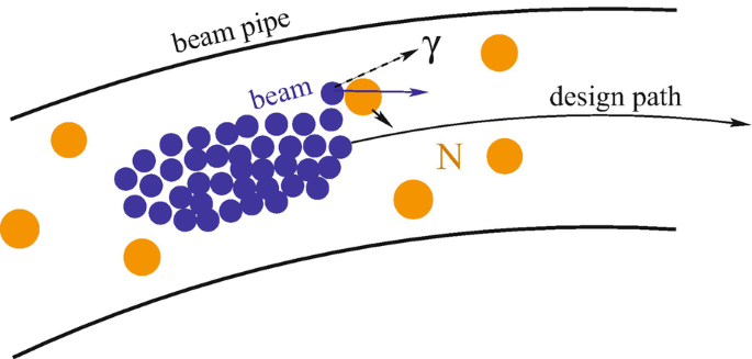
Schematic view of beam collisions with the nuclei (N) of the rest-gas
-
Thermal photon scattering: inverse Compton scattering of electrons or positrons with photons from black-body radiation in the beam pipe; relevant for beam energies > 10 GeV
-
Intra-beam scattering: collisions or close encounters with other particles in the same beam; most relevant at lower energies and for very dense beams
-
Quantum lifetime: particles leaving the acceptance by quantum fluctuations in synchrotron radiation
-
Colliding beams: particle collisions or close encounters when beams cross in colliders

Estimates for the first two types which involve collisions with particles outside the beam will be given below.
The losses from the different loss mechanism have to be added. This implies, that the corresponding lifetime contributions add reciprocally
An example of observed lifetimes in LEP is listed in Table 5.1, where losses from intrabeam scattering were negligible.
The single beam lifetime is observed before beams are brought into collisions. In LEP this was dominated by the thermal photon scattering. LEP was generally operated with sufficient aperture and over-voltage from the RF-acceleration system, so that losses from the quantum lifetime were negligible. More details on lifetimes observed in LEP with a discussion of quantum lifetime and small, but non-negligible effects which made lifetimes longer than originally anticipated can be found in [12].
5.2.1 Beam-Gas
From ideal gas theory, the density ρ m in terms of molecules or atoms per unit volume is
Multiplying ρ m with the cross section σ for beam-gas collisions, gives us the collision probability per unit length
Further multiplication with the velocity of the beam particles v = βc gives us the collision rate per unit time
which corresponds to the inverse lifetime, if σ is the cross section for collisions which lead to a loss of the beam particles. This will be the case for inelastic scattering processes and for elastic scattering in which the scattering angle is larger than the angular acceptance.
For numerical estimates in this section we take ρ m = 3.26 × 10¹³ molecules/m3 which corresponds to a pressure of p = 1 Torr = 1.33 × 10⁻⁷ Pa at room temperature (T = 296.15 K = 23∘C) and can be considered as typical number for good vacuum conditions. At high energy we have β ≈ 1. For a cross section of σ = 1 b (one barn, where 1b = 10−28 m2), we obtain a beam-gas lifetime τ = 284 h.
The main beam-gas scattering processes are shown in Fig. 5.2.

Beam-gas scattering processes; elastic and inelastic eN scattering relevant for e+, e− machines is shown on the left and pN scattering relevant for proton machines on the right
eN Scattering Relevant for Electron Rings
The elastic cross section for eN scattering scales strongly with energy (with 1∕γ 2) and scattering angle 1∕θ 4. Elastic scattering is mostly relevant as a halo production process for lower energy rings and becomes negligible for lifetime estimates for high energy electron rings.
At high energy, the dominating beam-gas process for electron rings is the inelastic scattering or bremsstrahlung in which the incident electron interacts with the field of the residual gas nucleus and radiates a photon.
The high energy cross section for eN scattering can be written in good approximation in dependently of the electron energy as [13]
where k min is the fractional energy loss or minimum photon energy in units of the electron energy, α the fine-structure constant (1∕137) and Z the atomic number (or number of protons). We can see that the cross section scales with Z(Z + 1). Numerical values obtained from Eq. 5.4 for k min = 0.01 are shown in Table 5.4.
pN Scattering Relevant for Electron Rings
At high energies (p lab > 10 GeV), the pN cross section is mostly inelastic (> 80%). It depends only weakly on the proton energy and scales approximately with the atomic mass ∝ A 2∕3 [14], as can be expected for the cross-section of a sphere. Numerical values are listed in Table 5.2. We can see that pN cross sections are much smaller (∼10 ×) than eN cross sections. Good beam-gas lifetimes in proton machines can be several 103 h compared to typically 102 h in high energy electron machines.
5.2.2 Thermal Photons
Even a perfectly evacuated beam pipe remains “filled” with photons from black body radiation which can be relevant as source of backgrounds and reduction of beam lifetime as first pointed out by V. Telnov in 1987 [15]. The photon density from black-body radiation is
where T is the absolute temperature, and k,h,c the Boltzmann, Planck constants and the speed of light. For a beam pipe at room temperature (23∘C), we get a photon density of ρ γ = 5.3 × 10¹⁴ m−3 which is an order of magnitude higher than the typical residual gas molecular densities ρ m, considered in this chapter for beam gas estimates (Fig. 5.3).

Schematic view of the inverse Compton scattering with thermal photons. A high energy beam particle collides and loses energy to a low energy photon radiated from the beam pipe by black body radiation
The lifetime from thermal photon scattering is
where ρ γ is the photon density, σ C the Compton cross section (at high energy ∼ 0.665 barn) and f loss the fraction of the e± lost after collision. Numerical values calculated using the program described in [16] are given in Table 5.3. We can see that thermal photon scattering at room temperature becomes only relevant for electron beam energies above 10 GeV.
5.2.3 Luminosity Lifetime
In analogy to Eq. 5.1, the luminosity L lifetime is defined as
The luminosity for colliding beams depends on the product of the colliding beam intensities, or N 2 in case of equal beam intensities. At constant beam sizes, the luminosity decreases as dN 2∕dt = 2dN∕dt, so that the luminosity lifetime is half of the intensity lifetime τ L = τ∕2. For operation at the beam-beam limit as is typical for high luminosity e+e− storage rings, beam sizes increase with intensity such that the beam-beam parameter is constant, and L ∝ N and therefore τ L = τ. In proton machines, beam sizes tend to increase with time due to intrabeam scattering, noise and vibrations, resulting in luminosity lifetimes τ L < τ∕2.
5.3 Experimental Conditions
The most important performance parameters for colliders for particle physics are
-
the beam energy; higher beam energies allow to study smaller distances and to produce new heavier particles;
-
high luminosity to obtain sufficient collisions rates to observe new processes or to improve the measurement precisions.
It is also essential to provide good experimental conditions for the particle detectors installed around the collision regions. Criteria for good experimental conditions are
-
low backgrounds;
-
good knowledge and stability of beam parameters;
-
minimize the risk of damage of the detectors by beam loss and irradiation;
-
minimize the size of the beam pipe in the detector region to allow for the installation of vertex detectors as close as possible to the interaction region;
-
maximize the space available for the detector and the solid angle coverage down to low angles close to the beam.
These are rather conflicting requirements. Minimizing the size of the beam pipe for installation of sensitive vertex detectors close to the beam pipe will increase the background rates hitting the detector region and increase the risk of damage by beam loss. The requirements for maximum space and solid angle coverage for the detectors are also in conflict with the requirements of the accelerator to maximize luminosity by
-
allowing for space close to the interaction point for final focus quadrupoles;
-
reducing the β-function at the interaction point, which increases the beam size in the final focus quadrupoles with the risk to create local aperture limits and losses and which limits the space and low angle coverage available for particle detection;
-
installation of beam-separators close to the interaction region to allow to fill the machine with many bunches.
It is essential to consider the accelerator and detector requirements together, both during the design stage and also later in the optimization of the running parameters.
Experience shows that it typically takes several years to commission and optimize the performance of a new accelerator. During these first years, it will often be possible to increase the luminosity without compromising on the experimental conditions for the detectors. Detailed simulation and continuous monitoring of the background conditions are important to identify potential limitations, to guide further optimization and to identify the potential for upgrades towards higher luminosities or smaller beam pipes.
Different types of backgrounds and their mitigation with examples from LEP and LHC are now discussed.
5.3.1 Sources of Detector Background and Detector Performance
It is possible to distinguish between two main types of machine induced backgrounds
-
backgrounds induced by losses of beam particles;
-
background from synchrotron radiation, relevant for high energy e+, e− beams.
Machine induced backgrounds by particle loss are relevant for all (circular and linear) colliders. Even under good conditions, millions of particles will be lost per second, exceeding by several orders of magnitude the beam crossing rates, see Table 5.4. A minimum requirement is that only a very small fraction of these particles gets lost close to the detector, such that the background rate in the interaction region is small compared to the bunch crossing rates.
To achieve this one has to assure
-
good vacuum conditions in the region around the detectors, in order to minimize local losses by beam-gas scattering in the detector region;
-
that there is no aperture limitation which would concentrate losses close to the detectors.
the latter imposes limits on the minimum β in the interaction region and hence the maximum luminosity. A standard method to reduce backgrounds from particle losses is to use aperture limiting collimators to remove high amplitude halo particles. These should be placed far from the experiments, to minimize the probability that secondary particles scattered off the collimators reach the experiments.
For beam energies above about 50 GeV, the production of secondary muons in electromagnetic showers has to be taken into account. High energy muons are hard to shield. Muon production and shielding is taken into account in the design studies for high energy linear colliders [17, 18].
The final focus quadrupoles placed around the interaction regions of colliders generate a high local chromaticity which can lead to a concentration of losses of off-momentum particles into the detectors. LEP2 was equipped with momentum collimators in the dispersion suppressors around all experimental sections to reduce the flux of off-momentum particle generated by e+e− collisions, bremsstrahlung in the residual gas and thermal photon scattering.
5.3.2 Synchrotron Radiation Background
The energy spectrum of the synchrotron radiation photons radiated by a high energy electron (or positron or proton) travelling on a circular orbit of radius ρ is characterised by the critical energy
The number of photons radiated in a bending magnet of length L and bending radius ρ is (α = e 2∕ 4π𝜖 0 ħc is the fine-structure constant and γ the Lorentz factor of the particle) and the energy loss U 0 per beam particle and turn are
The photon energy increases with γ 3 and the energy loss in synchrotron radiation over one turn as γ 4. A practical limit was reached with electrons at LEP at beam energies around 100 GeV, corresponding to a Lorentz factor γ ≈ 2 × 10⁵ when 3% of the particle energy was lost on a single turn, while for the 1836 times heavier protons synchrotron radiation only becomes noticeable at TeV energies. Numerical values for the main synchrotron radiation parameters for several e+e− colliders, the LHC with protons at 7 TeV and the proposed FCC colliders[23, 24] are shown in Table 5.5.
The normalised quadrupole power spectrum (for flat beams as typical for e+, e− colliders) is
Half of the power is radiated below the critical photon energy.
Quadrupoles can be considered as bending magnets which increase in strength with the distance from the magnet axis. The equations given above also hold for quadrupoles for Gaussian beams if we take as ρ the bending radius of the quadrupole at 1σ offset from the beam axis [19]. The normalised quadrupole power spectrum is
and is shown in Fig. 5.4 together with the spectrum for a dipole.

Normalised power spectra for synchrotron radiation in a dipole and a quadrupole
Averaged over the ring, the synchrotron power radiated in the quadrupoles remains usually very small compared to the power radiated in the main dipole magnets. Due to the vicinity and strength of the quadrupoles around the experiments, it is mandatory to include these in background estimates and also important to consider the possibility of non-Gaussian tails which increase the synchrotron radiation from quadrupoles.
Background estimates for synchrotron radiation depend critically on design details: the magnet lattice, beam pipe geometry, materials and beam parameters. Estimates were often done using dedicated “home-grown” programs with ad-hoc interfaces between separated simulations of the accelerator components, synchrotron radiation generation and simulation of the interactions in the detectors. More recently it has become feasible with the programs BDSIM and MDISim, both based on GEANT4, to perform more flexible integrated simulations which include all relevant components and processes [21, 22].
We will now shortly look at LEP2 which had the strongest synchrotron radiation of all colliders and still tolerable background levels for the detectors. The amount of synchrotron radiation in LEP was huge, particularly at LEP2 energies: about 6 × 10²⁰ photons were emitted per second and a power of 18 MW lost to synchrotron radiation. The experiments had to be very well screened using a sophisticated collimation system with about 100 movable collimators and in addition fixed masks close the experiments [20]. The typical layout of the collimators in a straight section, where only scattered synchrotron light could reach the detectors, is shown in Fig. 5.5. The synchrotron radiation spectrum is broad and photons down to about 20 keV can leave the beam pipe. The lower energy X-ray radiation can undergo low angle (multiple) reflection. The strong radiation from the main dipoles of LEP was intercepted close to the arcs, with collimators located between 100 and 220 m away from the interaction point, before the photons could be scattered at low angle towards the experiments. To reduce the radiation shining into the straight sections further, the first dipoles in the arcs had only 10% of the field of the normal arc dipoles.

Schematic layout of a straight section at an interaction point (IP) of LEP in the horizontal (top) and vertical (bottom) planes. Shown are the locations of the quadrupoles (QS), electrostatic separators (ES) and collimators (COLH, COLV, COLZ). The solid lines mark the inner vacuum chamber radii
Local masks were installed about 2.4 m from the interaction points to improve the shielding of the experiments from the increased synchrotron radiation at LEP2. The collimators and masks close to the interaction point were however also a source of scattered background particles. The surface material and inclination of the masks was optimized to minimize the scattering towards the experiment: the masks were made of tungsten and the surface coated with silver and copper layers to reduce the emission of fluorescence photons.
The background photons observed in the detectors originated mainly from synchrotron radiation in the last quadrupoles and was backscattered into the experiment from local collimators. The bunch crossing rate in LEP was about 45 kHz and typically only a few background photons were recorded per bunch crossing in the large wire chambers of the LEP detectors. There was no problem with detector occupancy, but the currents drawn in the gas-chambers were reported to be not too far from the tolerable limit. The experience gained with LEP has been essential for the design studies for a possible future circular lepton collider at CERN [23, 25].
References
G. Battistoni et al., Overview of the FLUKA code, Annals of Nuclear Energy 82 (2015) 10–18.
T.T. Bohlen et al., The FLUKA Code: Developments and Challenges for High Energy and Medical Applications, Nuclear Data Sheets 120 (2014) 211–214.
S. Agostinelli et al., GEANT4-A simulation toolkit, Nuclear Instruments and Methods in Physics Research A 506 (2003) 250–303.
J. Allison et al., Recent developments in GEANT4, Nuclear Instruments and Methods in Physics Research A 835 (2016) 186–225.
N.V. Mokhov and C.C.James, The MARS Code System User’s Guide, Version 15, (2016), https://mars.fnal.gov
N.V. Mokhov and S.I. Striganov, MARS15 Overview, Proceedings of the Hadronic Shower Simulation Workshop 2006, Fermilab 6–8 September 2006, M. Albrow, R. Raja eds., AIP Conference Proceeding 896 (2007).
C.J. Werner ed., MCNP User’s Manual, Version 6.2, Los Alamos National Laboratory report, LA-UR-17-29981 (2017).
T. Sato et al., Features of Particle and Heavy Ion Transport code System (PHITS) version 3.02, J. Nucl. Sci. Technol. 55 (2018) 684–690.
Y. Iwamoto et al., Benchmark study of the recent version of the PHITS code, J. Nucl. Sci. Technol. 54 (2017) 617–635.
A. Lechner et al., Validation of energy deposition simulations for proton and heavy ion losses in the CERN Large Hadron Collider, submitted to Physical Review Accelerators and Beams (2019), https://doi.org/10.1103/PhysRevAccelBeams.22.071003.
A. Peters, H. Schmickler, K. Witternburg (Editors), “Proceedings of Workshop on DC Current Transformers and Beam-Lifetime Evaluations, Lyon 2004”, CARE-Note-2004-023-HHH
H. Burkhardt, “Beam Lifetime and Beam Tails in LEP”, Proc. e+e− factories, KEK 1999, CERN-SL-99-061-AP (1999)
Y.-S. Tsai, “Pair production and Bremsstrahlung of charged leptons,” Rev. Mod. Phys. 46 (1974) 815–851.
J. Letaw, R. Silberberg, and C. Tsao, “Proton-nucleus inelastic cross sections: an empirical formula for E> 10 MeV”, The Astrophys. Journ.Suppl.Ser. 51, (1983), pp 271–276
V. I. Telnov, “Scattering of electrons on thermal radiation photons in electron - positron storage rings”, Nucl. Instrum. Meth. A260 (1987) 304,
H. Burkhardt, “Monte Carlo Simulation of Beam Particles and Thermal Photons”, July, 1993. CERN SL Note 93-73 (OP).
I. Agapov, H. Burkhardt, D. Schulte, A. Latina, G. A. Blair, S. Malton, and J. Resta-López, “Tracking studies of the Compact Linear Collider collimation system,” Phys. Rev. ST Accel. Beams 12 (Aug, 2009) 081001. 10.1103/PhysRev STAB.12.081001
H. Burkhardt, G. A. Blair, and L. Deacon, “Muon Backgrounds in CLIC”, Proc. IPAC 2010
E. Keil, “Synchrotron Radiation from a Large electron-Positron Storage Ring”, CERN-ISR-LTD-76-23, June 1976
G. von Holtey, A. Ball, et al., “Study of beam-induced particle backgrounds at the LEP detectors”, Nucl. Instrum. Meth. A403 (1998) 205–246, https://doi.org/10.1016/S0168-9002(97)01094-2.
L. Nevay et al., BDSIM: An Accelerator Tracking Code with Particle-Matter Interactions. https://urldefense.proofpoint.com/v2/url?u=https-3A__arxiv.org_abs_1808.10745v1&d=DwI FaQ&c=vh6FgFnduejNhPPD0fl_yRaSfZy8CWbWnIf4XJhSqx8&r=XRE98stjh0DZlXWNY x-jk11s49AfQ9rwMw8TKownaLA&m=nT9ubpnYZV6ASvZRvylWgRRpic9Q8sGOtaj0hV sLltE&s=sVWR0RTCWGrRe0NT2jXWKQJUXrvTIg_zydlInZnlwOs&e=
H. Burkhardt and M. Boscolo. Tools for Flexible Optimisation of IR Designs with Application to FCC. In Proc IPAC 2015, https://doi.org/10.18429/JACoW-IPAC2015-TUPTY031.
A. Abada et al. FCC-ee: The Lepton Collider. https://doi.org/10.1140/epjst/e2019-900045-4. [Eur. Phys. J. ST228,no.2,261(2019)].
A. Abada et al. FCC-hh: The Hadron Collider. Eur. Phys. J. ST, 228 (4): 755–1107, https://doi.org/10.1140/epjst/e2019-900087-0.
M. Boscolo, H. Burkhardt, and M. Sullivan. Machine detector interface studies: Layout and synchrotron radiation estimate in the future circular collider interaction region. Phys. Rev. Accel. Beams, 20 (1): 011008, 2017. https://doi.org/10.1103/PhysRevAccelBeams.20.011008.
Author information
Authors and Affiliations
Corresponding authors
Editor information
Editors and Affiliations
Rights and permissions
Open Access This chapter is licensed under the terms of the Creative Commons Attribution 4.0 International License (http://creativecommons.org/licenses/by/4.0/), which permits use, sharing, adaptation, distribution and reproduction in any medium or format, as long as you give appropriate credit to the original author(s) and the source, provide a link to the Creative Commons license and indicate if changes were made.
The images or other third party material in this chapter are included in the chapter's Creative Commons license, unless indicated otherwise in a credit line to the material. If material is not included in the chapter's Creative Commons license and your intended use is not permitted by statutory regulation or exceeds the permitted use, you will need to obtain permission directly from the copyright holder.
Copyright information
© 2020 The Author(s)
About this chapter

Cite this chapter
Brugger, M., Burkhardt, H., Goddard, B., Cerutti, F., Alia, R.G. (2020). Interactions of Beams with Surroundings. In: Myers, S., Schopper, H. (eds) Particle Physics Reference Library . Springer, Cham. https://doi.org/10.1007/978-3-030-34245-6_5
Download citation
DOI: https://doi.org/10.1007/978-3-030-34245-6_5
Published:
Publisher Name: Springer, Cham
Print ISBN: 978-3-030-34244-9
Online ISBN: 978-3-030-34245-6
eBook Packages: Physics and AstronomyPhysics and Astronomy (R0)