

Abstract
Using prestressed carbon fiber reinforced polymer (CFRP) tendons to strengthen glulam beams is a promising approach to improve their load-carrying capacity and crack resistance. Reliable anchorage is critical for ensuring the overall performance of the beam. In this paper, a threaded sleeve bonded anchorage was developed for CFRP prestressing tendons in glulam beams. Pullout tests were conducted on a series of bonded anchorage specimens with different sleeve lengths. The test results show that the main failure modes of the anchorage were the fracture of CFRP tendons. Increasing sleeve length reduced the maximum slip at the CFRP-adhesive interface but enhanced its capacity. As the sleeve length increased from 150 to 250 mm, the maximum slip decreased by 13.6%, with the ultimate tensile capacity increasing by 4.6%. A finite element model was then developed for the bonded anchorage. It was verified based on the pullout test results and utilized in a parametric study to further explore the anchorage behavior. The results indicate that longer sleeve length led to more uniform distributions of both axial and radial stresses along the CFRP tendon. Increasing elastic moduli of adhesive reduced the maximum slip and resulted in less uniform radial stress distributions of CFRP tendons.
Introduction
Glulam is an engineered wood product processed by gluing multiple layers of timber together. Compared to traditional sawn lumber, it exhibits better mechanical properties and dimensional stability, making it widely used in the fabrication of beams, columns, etc. [1, 2]. However, the failure mode of glulam beams is still characterized by the initiation and propagation of tensile cracks due to the natural defect of timber materials: when brittle failure occurs due to tensile cracks from defects within the tension zone, the compressive strength of glulam is far from fully utilized in the compression zone [3, 4]. The premature development of cracks greatly influences the design of serviceability and ultimate limit states for glulam beams, especially in large-span applications. Several solutions have been proposed to address the premature development of cracks in glulam beams. One is incorporating prestressed tendons into the beams, mitigating premature cracking in the tension zone and improving material efficiency in the compression zone [5]. The tendons could be fabricated using steel [6, 7], carbon fiber reinforced polymer (CFRP) [8, 9], basalt fiber reinforced polymer (BFRP) [10], Glass Fiber Reinforced Polymer (GFRP) [11]. CFRP not only has great corrosion resistance and high longitudinal tensile strength, but also has advantages such as high temperature resistance and fatigue resistance compared to other fiber polymer materials, making it a popular choice for reinforcing timber members recently [12, 13]. However, CFRP is an anisotropic material, and its transverse shear strength is relatively low. The CFRP reinforced glulam beam is potentially characterized by an unexpected failure mode under bending (i.e., anchorage failure with the CFRP tendon severed at the anchorage end), if the conventional anchoring system for steel tendons is employed [14]. Previous studies on CFRP-reinforced glulam have primarily focused on the use of CFRP strips [15, 16]. There are few studies concerning CFRP tendon anchoring performance in glulam.
Although there is a lack of studies specifically focusing on anchorage techniques for CFRP tendons in glulam beams, existing anchorage systems for CFRP in other structural components are available [17]. The existing anchorage systems can be categorized into three types according to their anchoring mechanisms: mechanical anchorages, bonded anchorages, and composite anchorage. Mechanical anchorages are also known as friction-type anchorages [18]. Their anchoring mechanism works through friction between clamps and sleeves, as well as friction between sleeves and tendons. Bonded anchorages transmit shear forces through the bonding stress on the interface. The bonding force at the anchorage interface primarily comes from shear mechanisms, including chemical adhesion, frictional resistance, and mechanical interlocking force [19]. In previous research, these bonding forces are generally not strictly distinguished, and are instead simplified into a single resultant force. Composite anchorages are composed of two or more mechanical and bonded anchorages connected in series or parallel to combine their advantages [20].
Each anchorage type has its pros and cons. Compared to mechanical anchorages, bonded anchorages can help mitigate stress concentration and achieve better fatigue performance. A series of studies have been carried out on the mechanical property of CFRP tendon bonded anchorages, with several types of adhesives proposed in previous studies [21,22,23]. The bonding performance at the interface varies depending on the surface morphology of the CFRP bar, the type of adhesive, and the normal constraint stress on the bonding surface. Zhang et al. [24, 25] conducted pull-out tests on CFRP tendon anchorages filled with cement mortar. They found that the surface morphology of the tendon had a crucial impact on the pull-out resistance of the anchorage. Al-Mayah et al. [26] carried out experimental and analytical investigations on a stainless-steel anchorage for CFRP prestressing tendons. The results showed that the bond strength of CFRP tendons increased to 2–3 times the original value after the resin-enriched layer was removed since the resin-enriched layer is usually smooth and has low cohesion strength. Wang et al. [27] and Feng et al. [28] designed an internal conical bonded anchorage with layered infusion of variable stiffness adhesive medium. The bonding medium was cast in four layers, with its modulus of elasticity decreasing from the free end to the loading end. Such an anchorage system could distribute uniform circumferential stress to the tendon, mitigating shear-induced failure of the tendon at the anchorage end. Puigvert et al. [29] conducted experimental creep tests and fatigue tests for bonded anchorage systems. Following the experimental results, they further developed a finite element (FE) model that could successfully predict the fatigue and creep properties of bonded anchorage systems. They found that the lifespan of anchorages was shorter at higher loads. Fang et al. [30, 31] experimentally studied on the bonded anchorages with either single or multiple CFRP tendons, and established formulas to calculate the bond strength and critical bond length between CFRP tendons and concrete grout. Mei et al. [32, 33] carried out experimental tests to explore the bond-slip behavior of CFRP tendons in anchorages and the multi-axial stress in steel sleeves. The results showed that conical anchorages significantly reduced tendon slip and improved anchorage efficiency.
Although the existing research offers valuable insights into anchorage techniques for CFRP tendons, there is still a lack of research on the anchorage of prestressed CFRP tendons in glulam. It is necessary to develop anchorage systems suitable for CFRP tendons in prestressed glulam beams and study their anchorage behaviors given the following two reasons: (1) the conclusions drawn from existing research may be affected in the application scenario of glulam beams due to the significantly different mechanical properties of glulam compared to concrete and steel; and (2) reliable anchorage systems are crucial for ensuring the quality and durability of prestressed glulam beams. To shed some light on this topic, a threaded sleeve bonded anchorage was developed for CFRP prestressing tendons in glulam beams in this study. Pullout tests were conducted for the anchorages with sleeve length as the variable. The pullout properties of the anchorage specimens were compared in terms of failure modes, load-slip relationships, and anchorage efficiency. A FE modeling method was then developed for the bonded anchorage for CFRP prestressing tendons in glulam beams. The modeling method was validated by the pullout test results, and was further used in a parametric study to investigate the impact of sleeve length and elastic moduli of the adhesive on the anchorage behavior.
Materials and methods
Configuration of the bonded anchorage for CFRP prestressing tendons in glulam beams
Figure 1 illustrates the configuration of the bonded anchorage designed for CFRP prestressing tendons in glulam beams. Such an anchorage system consists of a steel sleeve, epoxy adhesive, CFRP tendons, and nuts. The sleeve is bonded with adhesive at the end of the CFRP tendon as the anchorage. It features a cylindrical configuration with external threading to facilitate assembly. After the CFRP tendons are tensioned to achieve the target prestress, tightening the nut on the sleeve can prevent the CFRP tendons from retracting and maintain the prestress. A limiting ring is welded at the inside end of the sleeve to maintain concentric alignment of the CFRP tendon, with the outside end sealed with a rubber stopper. A steel plate is set between the nut and glulam beam, aiming to achieve effective stress transmission and mitigate stress concentration. Such a configuration (using external threads and nuts on the sleeve) is expected to ensure reliable anchorage of the CFRP tendon to prevent pull-out. During the fabrication of prestressed glulam beams, the CFRP tendon must first be inserted into the beam tunnel, followed by the installation of bonded anchorages at both ends. The limiting ring on anchorage and the steel plate at the end of beam are designed to prevent the adhesive inside anchorage from entering beam tunnel. After the prestress tensioning is completed, whether to inject the adhesive into the glulam beam tunnel can be selected according to the engineering requirements.

Threaded sleeve bonded anchorage for CFRP prestressing tendons in glulam beams
Specimen design of pullout tests
The experimental testing program had a total of nine test specimens, divided into three groups of different sleeve lengths (each with three replicates). Figure 2 shows the test specimens of the bonded anchorage for CFRP prestressing tendons in glulam beams. Apart from sleeve lengths, identical configurations and dimensions were employed for all the specimens to facilitate comparison. The dimensions and manufacturer-provided material properties of the CFRP tendons are summarized in Table 1. The threaded steel sleeves were manufactured from carbon steel with a yield strength of 355 MPa and an elastic modulus of 209 GPa. The outer and inner diameters of the sleeves were respectively 33 and 18 mm. The bond medium utilized epoxy resin adhesive with a uniform thickness of 4 mm. Table 2 gives the mechanical characteristics of the adhesive, which were sourced from the manufacturer. The three experimental groups, designated S150, S200, and S250, were assigned sleeve lengths of 150, 200, and 250 mm, respectively.

Threaded sleeve bonded anchorage specimens (unit: mm)
Test setup and loading protocol
Figure 3 shows the test setup and instrumentation for the bonded anchorage specimens in the pullout tests. The nine specimens had the identical test setup and instrumentations. One side of the bearing pedestal (shown in Fig. 3) was grooved for installation. It was because the performance of bonded anchorage primarily depends on the sleeve, CFRP tendon, and the adhesive between them. Using the steel pedestal to instead of timber as the load-bearing device can effectively simplify the installation process while having minimal influence on the results. A steel connector was employed to connect the sleeve to the jack, which applied the prestressing force to the CFRP tendons. The applied prestressing force was measured by a load sensor was set between the tensioning pedestal and the jack. A pair of Linear Voltage Displacement Transducers (LVDTs) were respectively installed at the sleeve and the CFRP tendon, recording their displacements during the tests. The slip of CFRP tendon was obtained by calculating the difference between their displacements. The sampling frequency of the LVDTs was 2 Hz.

Test setup and instrumentation
The loading protocol of the pullout tests was determined according to the Chinese code for anchorage of prestressing tendons [34]. The bonded anchorage specimens were loaded with a rate of 200 MPa/min up to 50% of the nominal ultimate tensile strength (Fptk). The load was then held for 10 min before being gradually increased to failure.
Results and discussion
Experimental observations
Figure 4 shows the failure modes of the bonded anchorage specimens. The main failure modes of all the specimens were characterized by the fracture of CFRP tendons. For the specimens in group S250, only structural tightening was detected during initial loading stages. When the load reached around 100 kN, fiber breakage was observed. At the end of the test, the middle part of the CFRP tendon experienced sudden fracture failure. For group S200, two of the three specimens (S200-2 and S200-3) exhibited complete CFRP tendon rupture, representing the typical failure mode. However, S200-1 demonstrated a different failure mode. During loading, distinct slippage sounds indicated interfacial degradation. Subsequently, the CFRP tendon experienced a partial rupture near the sleeve end, characterized by the fracture of a portion of the fibers while the remaining intact fibers maintained continuity. The entire specimen lost its bearing capacity. The inspection after test revealed localized fiber fracture on the CFRP tendon surface, with the unruptured section appearing visually intact. Slippage sounds were observed between the adhesive and CFRP tendons during the loading process of S200-1, indicating that its slip was more obvious than the other two specimens. The partial rupture failure of S200-1 could be attributed to the surface damage to the CFRP tendon during the slippage process. The failure mode of group S150 was similar to that of group S200. Fracture failure occurred in two of the three specimens during loading, while the other one exhibited partial rupture near the sleeve end with slippage sounds.

Failure mode of the test specimens
Comparing the failure modes of the three groups, the 250 mm sleeve length was sufficient to effectively prevent bonding quality issues. It ensured reliable bonding force and minimized CFRP tendon-adhesive slippage, by which CFRP tendon strength could be fully utilized. However, when the sleeves were 200 mm or 150 mm, the bonding might not be reliable enough given the significant slippage between the CFRP tendon and adhesive.
Anchorage properties
Figure 5 presents the load-slip relationships of the bonded anchorage specimens, with their properties given in Table 3. The load-slip curves exhibited a clear step-like pattern due to the incremental increase in load. All specimens basically exhibited a linear increase in slip with load until the ultimate load, at which the CFRP tendons failed. This also suggests that the CFRP tendon exhibits negligible plasticity. The primary focus for bonded anchorage is the deformation and failure modes of the test specimens, as well as their corresponding ultimate capacity and maximum slip. The occurrence of significant CFRP-adhesive slippage is undesirable, since it indicates the bonding quality issues. Therefore, the experimental results were evaluated based on the observed deformation and failure modes, with the ultimate capacity and maximum slip quantitatively verifying these modes.
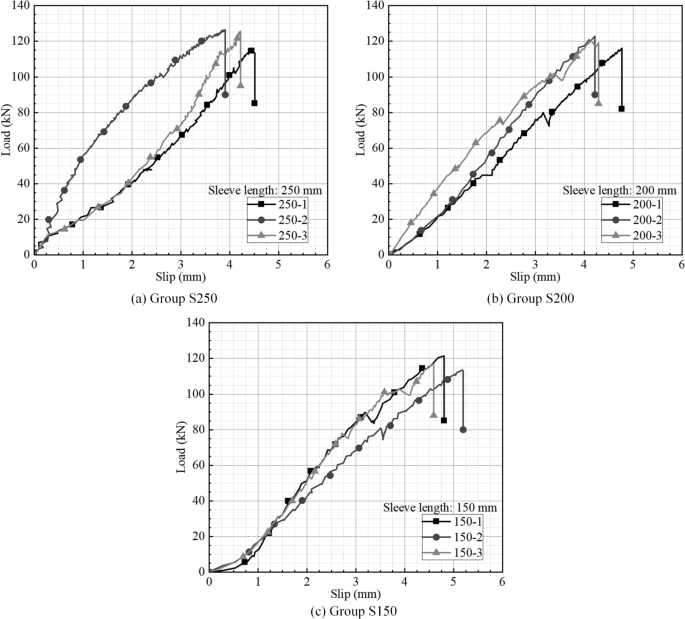
Load-slip curves of the bonded anchorage specimens
The specimens in group S250 exhibited identical failure modes, as well as comparable ultimate capacity and maximum slip. In contrast, groups S150 and S200 each had one specimen that exhibited a distinct failure mode, lower ultimate capacity, and greater slip. This indicates that failure mode significantly influences anchorage performance. In addition, minor variations in surface treatment, fiber distribution, or resin curing degree within the same batch of CFRP tendon may lead to differences in initial bond performance. In S250-2, the CFRP tendon had less resin layer on its partial surface due to manufacturing uncertainties, bring a tighter bond between the tendon and adhesive. This resulted in a stronger bond strength between the tendon and adhesive [26], which consequently exhibited higher slip stiffness in Fig. 5a. Moreover, material variability and assembly errors could also lead to different observed behavior. These could be the possible reasons behind the differences in the initial stage of the S200-3 curve. For all specimen groups, maximum slip was approximately 4–5 mm. Comparing the average ultimate capacities and maximum slip of the three groups, increasing the sleeve length reduced the maximum slip at the CFRP-adhesive interface and enhanced its capacity. As the sleeve length increased from 150 to 250 mm, the maximum slip decreased by 13.6%, with the ultimate tensile capacity increasing by 4.6%.
Table 3 also provides the anchorage efficiency coefficient (ηa) of the bonded anchorage specimens. The anchorage efficiency coefficient can be calculated by Eq. (1) according to the Chinese code for anchorage of prestressing tendons [34].
where FTu is the ultimate tensile capacity measured in the test; and Fptk is nominal ultimate tensile capacity of CFRP tendons. The results show that the average anchorage efficiency coefficients of the three groups reached 95.6, 93.0, and 91.3% respectively, exceeding the 90% minimum requirement specified in Chinese code for anchorage of prestressing tendons [34].
FE model
Modeling method
A nonlinear FE model was developed in the commercial software ABAQUS to further explore the pullout performance of the bonded anchorage used for CFRP prestressing tendons in glulam beams. Figure 6 shows the schematic of the FE modeling method. Figure 6a is the schematic diagrams of component instances. The components of the FE model in Fig. 6b correspond one-to-one with the instances. After applying prestress, the steel plate will be fixed at the glulam end by pressure. Compared to experiments, there is no installation difficulty in the FE model. Therefore, the glulam was employed as the load-bearing device in the FE model to represent the actual condition. All components are modeled with hexahedral elements, with a global seed size of 8 mm. A refined mesh (element size <5 mm) is applied to the interfacial interactions between tendons and adhesive. Four primary surface-to-surface contact pairs are defined in the model: (1) CFRP tendon and adhesive, (2) adhesive and sleeve, (3) sleeve and steel plate, and (4) steel plate and glulam. A stiffness-based master–slave surface assignment strategy is implemented, where surfaces with higher structural rigidity (e.g., steel plates) are designated as master surfaces, and compliant surfaces (e.g., glulam) serves as slave surfaces. The interactions are governed by the small sliding formulation to accommodate localized deformation characteristics. The limiting ring and nut are simplified using constraints to improve computational efficiency.

FE model for the bonded anchorage
The cross-section of the glulam beam end is fixed to fully restrain all degrees of freedom, as shown in Fig. 7a. One end of the sleeve is partially restrained, allowing only displacement along its axis and restricting its transverse and rotational movements. The loads are applied in two steps. Initially, pressure (i.e. P in Fig. 7b) is applied between the outer and inner adhesive walls, generating sufficient friction between the adhesive and the CFRP tendon to more accurately capture the anchorage sliding behavior. After that, axial tension (i.e. F in Fig. 7c) is applied to the free end of the CFRP tendon, to simulate the loading process during the test.

Boundary condition and loads of the FE model
Model validation
The model was verified with the data from the pullout tests on the bonded anchorage specimens. Its detailed dimensions are shown in Fig. 8. The anchor components (CFRP tendons, sleeves, and adhesive) were assigned material properties consistent with the experimental data in "Configuration of the bonded anchorage for CFRP prestressing tendons in glulam beams" section. The elastic modulus and the Poisson’s ratio of the steel plate is 209 GPa and 0.3, respectively. The beam was assumed to be manufactured from spruce-pine-fir glulam with a grade of TCT36 as per Chinese code for designing timber structures [35]. The mechanical behavior of the glulam beam was modeled using a homogeneous orthotropic model. Table 4 gives the parameters of the homogeneous orthotropic model, which were obtained from He et al. [36]. Table 5 lists the types and parameters for the contact behavior (including tangential, legal, and viscous behaviors), which were determined according to Cai et al. [37]. Pressure of 5 MPa was applied between the outer and inner adhesive walls. Such a pressure level was employed because it could sufficiently simulate the expected bonding effect without exceeding the load-carrying capacity of the adhesive.

Dimensions of FE model (Unit: mm)
Figure 9 shows the stress distributions of the anchorage system, taking group S250 as an example. For CFRP tendons, the maximum stress occurred at the loaded end and gradually decreased toward the opposite end due to interfacial bonding interactions between the tendon surface and bond medium. Fracture failure of the CFRP tendon was observed near the loaded end because of stress concentration. The stress distribution of the sleeve followed a similar trend that maximum stress happened at the loaded end, decreasing progressively toward the unloaded end. The stress of the sleeve came from both the tendon load transfer and the compressive interactions between the sleeve and steel plate. Compared to the CFRP tendon, the sleeve demonstrated a more uniform stress distribution, slower gradient variation, and reduced amplitude, indicating its stress-buffering role alongside the bond medium. High stress in the steel plate concentrated at the area near the sleeve. The stress decreased progressively toward the surrounding areas, demonstrating its effective stress dispersion capability. Compared to the steel plate, the glulam beam had a more uniform stress distribution. However, the high tensile load prevented the glulam beam from full stress dispersion, resulting in stress concentration at its bottom.

Stress distribution of the anchorage model (unit: MPa)
Figure 10 shows the experimental results along with the model predictions for the anchorage system. The displacement values of CFRP tendon and sleeve loading end were extracted. The slip was defined as the difference between these two values. This is consistent with the measurement method used in the experiment. The predictions of the load-slip response match well with the experimental results. For groups S150 and S200, the model accurately predicted the maximum slip with an error less than 8%. For the slip stiffness, the numerical results showed slight differences within 5% compared with the experimental results, indicating the effectiveness of the FE model. The test specimens in group S250 showed different experimental results due to the material variability of CFRP tendons. The model does not account for the uncertainty and therefore cannot accurately capture the behavior of all specimens. The bond length of the FE model of group S250 was the longest, producing high bond force under ideal bonding condition. So its slip curve was closer to that of S250-2, which has stronger bond strength between the tendon and adhesive. However, it is indeed necessary to pay attention to the material variability of CFRP tendons due to its non-negligible impact.

Test results and model predictions for the bonded anchorage specimen
Parametric analyses
The validated FE model was utilized in a parametric study, to further investigate the performance of sleeve bonded anchorages. A bonded anchorage with a 250-mm sleeve (configuration shown in Fig. 8) was employed as the benchmark model, with two parameters considered: sleeve length and the elastic modulus of the bond medium. It was because: (1) the sleeve length is expected to directly affect the contact area not only between the CFRP tendon and bonding medium, but also between the bonding medium and sleeve; and (2) the elastic modulus of the bonding medium is associated with interfacial characteristics.
Influence of sleeve length
Five sleeve lengths (200, 225, 250, 275, and 300 mm) were considered in the study. Figure 11 presents the load-slip curves of anchorages with varying sleeve lengths. All configurations exhibited consistent load-slip trends. The bonded anchorages exhibited a rapid load increase during initial loading phases, and the growth rate declined with the increasing slip. The bonded anchorages with longer sleeves exhibited increased stiffness, indicating improved load transfer uniformity due to the expanded contact area. Compared to the anchorage with 200 mm sleeve, the bonded anchorage with 300 mm sleeve showed a 33% reduction in maximum slip. Moreover, its load kept uniformly growing throughout the process, indicating its improved load-carrying capacity and stress distribution characteristics.

Load-slip curves of anchorages with different sleeve lengths
Figures 12 and 13 respectively compare axial and radial stress distributions along the CFRP tendon under 120 kN loading, where 0 mm represent the anchored end. The results in Fig. 12 show that the axial stress was slightly influenced by the sleeve length within the distance of 150 mm from the anchored end. The axial stress increased toward the loaded end until a distinct stress fluctuation occurred. The maximum values of the axial stress were comparable across all the anchorage models, with the 250 mm sleeve configuration exhibiting the lowest axial stress peak. When the sleeve lengths are 200 and 225 mm, the bonding length is relatively short, resulting in insufficient load transfer by the adhesive. Consequently, the peak axial stress near the loading end becomes higher. Sleeve lengths of 275 and 300 mm could provide enhanced structural stability and reduced stress fluctuations by creating a more stable stress transition zone. However, the excessive length introduces additional friction effect, leading to stress concentration. The 250 mm sleeve precisely meets the minimum effective bonding length required for adequate load transfer while avoiding the negative effects of excessive length, thus achieving the lowest peak axial stress.

Axial stress distribution of CFRP tendons with different sleeve lengths

Radial stress distribution of CFRP tendons with different sleeve lengths
The results of radial stress distributions show that, for all sleeve lengths, significant stress reduction occurred near the loaded end followed by stabilization. This indicates the localized stress concentration near the loaded end due to sleeve confinement. The bonded anchorages with larger sleeve length had lower radial stress peaks: the 300 mm sleeve achieving a 20% lower peak than the 200 mm configuration. This trend demonstrated that extended sleeves could promote more uniform radial constraint distributions, mitigating localized stress concentration and enhancing anchorage reliability. Note that, excessively long sleeve lengths could compromise both economic and structural feasibility. In practical engineering, the sleeve length should be minimized as long as the anchorage performance is ensured. In the parametric study, the 250 mm sleeve length is a suitable choice for CFRP tendons with a tensile force of about 120 kN.
Influence of elastic moduli of adhesive
The parametric analyses were also performed with elastic moduli of adhesive as the variable. Given that the elastic modulus of epoxy resin adhesive products commonly ranges from 1500 to 3500 MPa, the adhesive elastic modulus values of 1500, 2000, 2500, 3000, and 3500 MPa were considered. Figure 14 illustrates the load-slip curves of the bonded anchorages with the five adhesive elastic modulus values. The results show that increasing the elastic modulus of adhesive reduced the maximum slip of the anchorage. The configuration with the highest elastic modulus (3500 MPa) exhibited a 39% reduction in maximum slip compared to the lowest modulus case (1500 MPa).

Load slip curves of anchorages with different elastic moduli of adhesive
Figures 15 and 16 demonstrate the axial and radial stress distributions under varying adhesive elastic moduli at a 120-kN load. The results in Fig. 15 show that the axial stress of all the models exhibited comparable magnitudes and similar distributions (peak stresses happened near the loaded end), indicating the elastic modulus of adhesive had a limited impact on the axial stress distribution of the CFRP tendons. However, controlling the elastic modulus of adhesive is still necessary as excessive deformation of adhesive could result in uneven stress transmission. The results in Fig. 16 demonstrate that higher elastic moduli of the adhesive led to larger radial stress peak at the loaded end, while low elastic moduli (e.g., 1500 and 2000 MPa) exhibited a relatively smooth stress distribution at the loaded end. This indicates the beneficial effect of low elastic moduli in reducing stress concentration. However, the elastic modulus did not greatly influence the radial stress distribution along the CFRP tendon.

Axial stress distribution of CFRP tendons with different elastic moduli of adhesive

Radial stress distribution of CFRP tendons with different elastic moduli of adhesive
Conclusions
In this paper, a threaded sleeve bonded anchorage was developed for CFRP prestressing tendons in glulam beams. Pullout tests were conducted to investigate the anchorage performance of the bonded anchorage with varying sleeve lengths. The failure modes, load-slip responses, anchorage efficiency of the anchorage specimens were compared. A FE model was then developed for the bonded anchorage. The FE model was verified based on the pullout test results, and was utilized in a parametric study to investigate the influence of sleeve length and elastic moduli of adhesive on the anchorage behavior. The main conclusions are as follows:
-
(1)
The threaded sleeve bonded anchorage specimens could satisfy the anchoring requirements for CFRP tendons in prestressed glulam beams. The main failure modes of the bonded anchorage were characterized by the fracture of CFRP tendons. As the sleeve length increased from 150 to 250 mm, the maximum slip between the CFRP-adhesive interface decreased by 13.6%, with the ultimate tensile capacity increasing by 4.6%.
-
(2)
The developed FE model could well capture the pullout behavior of the threaded sleeve bonded anchorage. For slips up to 3.5 mm, the model accurately predicted the capacity with an error less than 7.0%.
-
(3)
The sleeve length greatly influenced the pullout performance of the threaded sleeve bonded anchorage. Longer sleeve length enhanced the stiffness of the anchorage and promoted more uniform distributions of both axial and radial stresses along the CFRP tendon. At a load of 120 kN, the configuration with a 300 mm sleeve demonstrated a 20% decrease in radial peak stress when compared to the 200 mm sleeve configuration.
-
(4)
Increasing the elastic modulus of adhesive reduced the maximum slip and led to a less uniform radial stress distribution of CFRP tendons. The maximum slip of the bonded anchorage decreased by 39% when the adhesive elastic modulus increased from 1500 to 3500 MPa.
Furthermore, the research also has some limitations. Due to the variability of materials and possible assembly errors, some CFRP tendons showed partial rupture during the pullout tests. This is not the ideal failure mode. And these factors could also lead to different observed behavior. Future research needs to focus on this issue to mitigate its influence.
Availability of data and materials
The datasets used and analyzed in the current study are available from the corresponding author on reasonable request.
Abbreviations
- CFRP:
-
Carbon fiber reinforced polymer
- BFRP:
-
Basalt fiber reinforced polymer
- GFRP:
-
Glass fiber reinforced polymer
- FE:
-
Finite element
- LVDTs:
-
Linear voltage displacement transducers
References
He M, Li M, Li Z, He G, Sun Y (2021) Mechanical performance of glulam beam-to-column connections with coach screws as fasteners. Arch Civ Mech Eng 21(2):51. https://doi.org/10.1007/s43452-021-00207-5
Wang X, He M, Dai P (2025) Experimental testing on the creep behavior of laminated veneer lumber (LVL) under various compression directions. Constr Build Mater 497:143877. https://doi.org/10.1016/j.conbuildmat.2025.143877
Shu Z, Gan X, Xie J, Dai Z, Li Z (2025) A macroscopic peridynamic approach for glulam embedment failure simulations. J Build Eng 106:112587. https://doi.org/10.1016/j.jobe.2025.112587
Li Z, Chen F, He M, Long W, Ou J, Li M (2023) Experimental investigation on self-centering steel-timber hybrid beam-column connections. J Struct Eng 149(3):04022256. https://doi.org/10.1061/JSENDH.STENG-11570
Wdowiak-Postulak A, Kawecki B (2025) Investigations on structural-sized GLT beams reinforced with steel and FRP composite bars: experimental tests and nonlinear numerical approach. Arch Civ Mech Eng 25(2):80. https://doi.org/10.1007/s43452-025-01123-8
McConnell E, McPolin D, Taylor S (2014) Post-tensioning of glulam timber with steel tendons. Constr Build Mater 73:426–433. https://doi.org/10.1016/j.conbuildmat.2014.09.079
Negrão JH (2016) Preliminary study on wire prestressing methods for timber pieces reinforcement. Constr Build Mater 102:1093–1100. https://doi.org/10.1016/j.conbuildmat.2014.11.050
Al-Hayek H, Svecova D (2014) Flexural strength of posttensioned timber beams. J Compos Constr 18:04013036. https://doi.org/10.1061/(ASCE)CC.1943-5614.0000431
Lv Q, Ding Y, Liu Y (2019) Effect of the nonprestressed/prestressed BFRP bar on flexural performance of the bamboo beam. Adv Polym Technol 2019:1–13. https://doi.org/10.1155/2019/7143023
McConnell E, McPolin D, Taylor S (2015) Post-tensioning glulam timber beams with basalt FRP tendons. Proc Inst Civ Eng - Constr Mater 168:232–240. https://doi.org/10.1680/coma.14.00032
Saad K, Lengyel A (2022) Strengthening timber structural members with CFRP and GFRP: a state-of-the-art review. Polymers Basel 14:2381. https://doi.org/10.3390/polym14122381
Abdalla JA, Ali AB, Hawileh RA, Mhanna HH, Galal KE, Saqan EI (2023) Effect of CFRP anchorages on the flexural behavior of externally strengthened reinforced concrete beams. Arch Civ Mech Eng 23(4):242. https://doi.org/10.1007/s43452-023-00784-7
Jung WT, Keum MS, Choi SY, Kang JY, Park JS (2014) A fundamental study on anchor performance of CFRP tendons with compressed anchor sleeve. Adv Mater Res 1061–1062:151–154. https://doi.org/10.4028/www.scientific.net/AMR.1061-1062.151
Zhao J, Mei K, Wu J (2020) Long-term mechanical properties of FRP tendon–anchor systems – a review. Constr Build Mater 230:117017. https://doi.org/10.1016/j.conbuildmat.2019.117017
Mercimek Ö, Ghoroubi R, Akkaya ST, Türer A, Anıl Ö, İşleyen ÜK (2024) Flexural behavior of finger joint connected glulam wooden beams strengthened with CFRP strips. Structures Oxford 66:106853. https://doi.org/10.1016/j.istruc.2024.106853
Turker YS, Kilincarslan S, Avcar M (2025) Mechanical behaviors of glulam beam-to-column joints strengthened with fiber-reinforced polymer composites: experimental investigation, numerical analysis and ANN prediction model. Compos Struct 359:118983. https://doi.org/10.1016/j.compstruct.2025.118983
Li Y, Shi T, Qiu Y, Zhu Y, Zhang L (2024) Anchorage research for CFRP tendons: a review. Mater Basel 17:3208. https://doi.org/10.3390/ma17133208
Schmidt JW, Bennitz A, Täljsten B, Goltermann P, Pedersen H (2012) Mechanical anchorage of FRP tendons – a literature review. Constr Build Mater 32:110–121. https://doi.org/10.1016/j.conbuildmat.2011.11.049
Wang L, Zhang J, Xu J, Han Q (2018) Anchorage systems of CFRP cables in cable structures—a review. Constr Build Mater 160:82–99. https://doi.org/10.1016/j.conbuildmat.2017.10.134
Chen J, Fang Z, Fang W, Wang Q, Tan X (2025) Experimental study on the bond behavior of the CFRP bar – UHPC interface in composite anchorage. J Compos Constr 29:04025015. https://doi.org/10.1061/JCCOF2.CCENG-4936
Cosenza E, Manfredi G, Realfonzo R (1997) Behavior and modeling of bond of FRP rebars to concrete. J Compos Constr 1:40–51. https://doi.org/10.1061/(ASCE)1090-0268(1997)1:2(40)
El-Nemr A, Ahmed EA, Barris C, Joyklad P, Hussain Q, Benmokrane B (2023) Bond performance of fiber reinforced polymer bars in normal- and high-strength concrete. Constr Build Mater 393:131957. https://doi.org/10.1016/j.conbuildmat.2023.131957
Baena M, Torres L, Turon A, Barris C (2009) Experimental study of bond behaviour between concrete and FRP bars using a pull-out test. Compos Part B Eng 40:784–797. https://doi.org/10.1016/j.compositesb.2009.07.003
Zhang B, Benmokrane B, Chennouf A (2000) Prediction of tensile capacity of bond anchorages for FRP tendons. J Compos Constr 4:39–47. https://doi.org/10.1061/(ASCE)1090-0268(2000)4:2(39)
Zhang B, Benmokrane B (2002) Pullout bond properties of fiber-reinforced polymer tendons to grout. J Mater Civ Eng 14:399–408. https://doi.org/10.1061/(ASCE)0899-1561(2002)14:5(399)
Al-Mayah A, Soudki KA, Plumtree A (2001) Experimental and analytical investigation of a stainless steel anchorage for CFRP prestressing tendons. PCI J 46:88–100. https://doi.org/10.15554/pcij.03012001.88.100
Wang X, Xu P, Wu Z, Shi J (2015) A novel anchor method for multi-tendon FRP cable: concept and FE study. Compos Struct 120:552–564. https://doi.org/10.1016/j.compstruct.2014.10.024
Feng B, Wang X, Wu Z (2019) Static and fatigue behavior of multitendon CFRP cables with integrated anchorages. J Compos Constr 23:04019051. https://doi.org/10.1061/(ASCE)CC.1943-5614.0000982
Puigvert F, Crocombe AD, Gil L (2014) Fatigue and creep analyses of adhesively bonded anchorages for CFRP tendons. Int J Adhes Adhes 54:143–154. https://doi.org/10.1016/j.ijadhadh.2014.05.013
Fang Z, Zhang K, Tu B (2013) Experimental investigation of a bond-type anchorage system for multiple FRP tendons. Eng Struct 57:364–373. https://doi.org/10.1016/j.engstruct.2013.09.038
Zhang K, Fang Z, Nanni A (2016) Behavior of tendons with multiple CFRP rods. J Struct Eng 142:04016065. https://doi.org/10.1061/(ASCE)ST.1943-541X.0001535
Mei K, Seracino R, Lv Z (2016) An experimental study on bond-type anchorages for carbon fiber-reinforced polymer cables. Constr Build Mater 106:584–591. https://doi.org/10.1016/j.conbuildmat.2015.12.059
Mei K, Sun S, Li B, Sun Y, Jin G (2018) Experimental investigation on the mechanical properties of a bond-type anchor for carbon fiber reinforced polymer tendons. Compos Struct 201:193–199. https://doi.org/10.1016/j.compstruct.2018.05.153
GB/T 14370-2015. Anchorage, grip and coupler for prestressing tendons, State General Administration of the People’s Republic of China for Quality Supervision and Inspection and Quarantine (AQSIQ), Beijing, China; 2015.
GB 50005-2017. Standard for design of timber structures, Ministry of Housing and Urban-Rural Development of the People's Republic of China (MOHURD), Beijing, China; 2017.
He M, Wang Y, Li Z, Zhou L, Tong Y, Sun X (2022) An experimental and analytical study on the bending performance of CFRP-reinforced glulam beams. Front Mater 8:802249. https://doi.org/10.3389/fmats.2021.802249
Cai D, Xu Z, Yin J, Liu R, Liang G (2016) A numerical investigation on the performance of composite anchors for CFRP tendons. Constr Build Mater 112:848–855. https://doi.org/10.1016/j.conbuildmat.2016.02.202
Acknowledgements
The authors gratefully acknowledge National Natural Science Foundation of China (Grant NO. 52378256) for supporting this research.
Funding
This work was supported by National Natural Science Foundation of China (Grant NO. 52378256).
Author information
Authors and Affiliations
Contributions
Pengfei Dai: Writing—original draft, Investigation, Experiment, Formal analysis. Minjuan He: Writing—review & editing, Supervision, Funding acquisition, Conceptualization. Yufei Xiao: Finite element simulation, Analysis. Xijun Wang: Writing—review & editing, Methodology, Supervision.
Corresponding author
Ethics declarations
Competing interests
The authors declare that they have no known competing financial interests or personal relationships that could have appeared to influence the work reported in this paper.
Additional information
Publisher's Note
Springer Nature remains neutral with regard to jurisdictional claims in published maps and institutional affiliations.
Rights and permissions
This article is published under an open access license. Please check the 'Copyright Information' section either on this page or in the PDF for details of this license and what re-use is permitted. If your intended use exceeds what is permitted by the license or if you are unable to locate the licence and re-use information, please contact the Rights and Permissions team.
About this article

Cite this article
Dai, P., He, M., Xiao, Y. et al. Threaded sleeve bonded anchorage for carbon fiber reinforced polymer tendons in glulam beams: experimental testing and parametric simulations. J Wood Sci 72, 23 (2026). https://doi.org/10.1186/s10086-026-02270-z
Received:
Accepted:
Published:
Version of record:
DOI: https://doi.org/10.1186/s10086-026-02270-z