
Abstract
Obfuscation is a promising solution for securing hardware intellectual property (IP) against various attacks, such as reverse engineering, piracy, and tampering. Due to the lack of standard benchmarks, proposed techniques by researchers and practitioners in the community are evaluated by existing benchmark suites such as ISCAS-85, ISCAS-89, and ITC-99. These open source benchmarks, though widely utilized, are not necessarily suitable for the purpose of evaluating hardware obfuscation techniques. In this context, we believe that it is important to establish a set of well-defined benchmarks, on which the effectiveness of new and existing obfuscation techniques and attacks on them can be compared. In this paper, we describe a set of such benchmarks obfuscated with some popular methods that we created to facilitate this need. These benchmarks have been made publicly available on Trust-Hub web portal. Moreover, we provide the first evaluation of several obfuscation approaches based on the metrics and existing attacks using this new suite. Finally, we discuss our observations and guidance for future work in hardware obfuscation and benchmarking.
1 Introduction
With the rising costs of chip fabrication at advanced technology nodes and ever-increasing design complexity, today’s semiconductor industry has shifted to a predominantly fabless business model. In this model, a design house typically sources pre-designed and pre-verified hardware IPs from different sources including third party IP (3PIP) vendors, integrates them into a system-on-chip (SoC), and ships the final layout to an off-shore foundry for fabrication. This trend has resulted not only in decreased costs and quicker turnaround times but also in a plethora of security issues. Most notably, an untrusted off-shore foundry could engage in IP piracy, overproduction, malicious modifications (hardware Trojan insertion), and cloning. Further, once the chip enters the supply chain, it is also vulnerable to various reverse engineering attacks, which aim at extracting the design or specific secrets from a design.
The most prevalent method of protecting IPs today is IP encryption [19]. In this approach, electronic design automation (EDA) tools provide a platform for encrypting IP. System integrator needs to verify the correct functionality of the incorporated encrypted IP through functional verification and testing. Most EDA tools facilitate such verification in a secured environment. In a common scenario, EDA tool decrypts the IP during synthesis and the resultant netlist is usually unencrypted. Typically, the Design-For-Test (DFT) team needs unencrypted design of the system to insert additional test circuitry that would facilitate the post-production structural tests to verify the integrity of the IC. Previously, the existence of decrypted IP in design and fabrication cycle was not considered a security threat, based on the contract and trust between parties who were well-known to each other. However, as the semiconductor industry became a horizontal business model distributed across the globe, this trust becomes questionable. More severely, any rogue employee in the design or fabrication facility or any adversary with access to an unencrypted IP may become a potential security threat. For example, a malicious insider in the design house may sell the IP to a third party while claiming it as their own (IP piracy), use the IP in excess of their contracted limit (IP overuse), and intentionally perform malicious modification (hardware Trojans insertion) to make the IP vulnerable to certain attack or become less reliable in critical usage [12, 14]. Additionally, reverse engineering can be performed on the IP to understand design intent and retrieve the higher level of design for malign intention.
In order to protect hardware IP from these threats, the design needs to be unintelligible, even in decrypted form. Hardware obfuscation provides the option to effectively hide and disable the design, but still facilitate structural testing and static/dynamic parameter analysis [29, 34]. This convenience makes obfuscation a desirable method for security and an active field of research. In recent years, a large number of obfuscation techniques and attacks on obfuscation have been proposed. In most cases, researchers evaluate their techniques and attacks on circuits generated in an ad hoc fashion. Unfortunately, this makes it difficult to objectively evaluate their merits and compare their effectiveness against various metrics. Lack of well-designed benchmarks, which can facilitate objective and accurate evaluation of important properties of obfuscation and manifest the merits and limitations of an approach, has become a major barrier for the research community. To address this limitation, for the first time, we introduce a suite of new obfuscation benchmarks that provides the option to evaluate obfuscation methods and attacks accurately and establish a baseline for comparison. In this paper, we also present our experimental results on comparative analysis of popular methods in the field based on resiliency against noteworthy attacks. We also introduce a set of metrics to quantify characteristics of the circuit and obfuscation technique applied to it.
Our contributions in this paper include:
-
Generation of obfuscation benchmarks to evaluate existing and emerging obfuscation methods and attacks. This required implementing many of the approaches found in literature.
-
Introducing new obfuscation metrics such as reconvergence, differential entropy, verification failure, key structure, and performing analysis of their relation with overheads and attack resiliencies using the benchmarks.
-
Analyzing how obfuscation metrics can indicate resiliency of an obfuscated circuit and providing future directions and insight on how to improve, optimize, and utilize these benchmarks, metrics, and obfuscation methods.
The rest of the paper is organized as follows—Section 2 articulates the motivation behind our work. Section 3 discusses the existing work in hardware obfuscation that acts as a foundation for our benchmarking initiative. Section 4 presents details on the benchmark generation process. Section 5 discusses the metrics used to evaluate the benchmarks as well as the associated results of overheads and attack resiliencies. Section 6 provides directions for future research in this field, and Section 7 concludes the paper.
2 Motivation
Hardware obfuscation emerged in 2007–2008 to protect IP from threats in the semiconductor supply chain [2, 11, 34]. Since then, it has been gaining popularity among hardware security researchers, according to Google Scholar. As shown in Fig. 1, the number of publications on obfuscation in major conferences and journals was relatively static each year until 2013. Since 2014, there has been an exponential increase in obfuscation-related work. Note that while 2017 is not shown in the figure, as of this writing, it already has 22 more publications than 2016.

Trends of publication in hardware obfuscation
Unfortunately, even after many publication on numerous ways of obfuscation and new attacks, there has been no impartial standardized comparison platform to evaluate the advancements. Some researchers use ISCAS benchmarks [8, 9], while others are more comfortable with ITC [17]. For presenting attack models, researchers are forced to generate their own benchmarks because of the unavailability of any standard ones [41]. As a result, it is infeasible for designers to know the scalability or applicability of these methods, and relative analysis of the effectiveness of obfuscation or hardware overhead. Thus, it has become necessary to establish standard benchmarks for obfuscation with which the research community can evaluate their methods.
3 Background and Preliminaries
In this section, we briefly describe the various threats for IP designers that hardware obfuscation can prevent. Then, we will present the obfuscation methods that were considered to generate our suite of benchmarks. In the last part, we will describe two attacks on obfuscation that we utilize in evaluation of attack resiliencies, along with one designated attack defiant obfuscation.
3.1 Threats
The threats bore by 3PIPs have been analyzed extensively in literature. Supply chain vulnerabilities and threats are discussed in detail in [27, 37]. Also, Rostami et. al. categorized many of these threats in [33]. An overview of these attacks is enlisted with examples here and also shown in Fig. 2.
-
3PIP: Any rogue employee in 3PIP design house with access can sell, modify, overuse, or reverse engineer an IP as the design is open and visible in this phase.
-
SoC and DFT inserter: A malicious entity in SoC or DFT insertion phase with access to unencrypted IP can also sell, modify, or reverse engineer the design.
-
Untrusted foundry: Any adversary with access to the final GDSII file of the IC design might overproduce the design or sell it to a third party. They might reverse engineer the design to retrieve higher level description to exploit vulnerabilities.
-
Assembly, distributor, and user: An attacker in assembly and distribution stage or an end user does not have access to the original design. However, they might reverse engineer the fabricated IC. Although IC reverse engineering is a slow and expensive process, it has become more practical today with the advent of advanced imaging and probing techniques such as focused ion beam (FIB) and scanning electron microscopy (SEM). In order to reverse engineer the design, an attacker needs to perform delayering, high-resolution imaging or X-raying, and image processing to retrieve the netlist from a fabricated IC. If the adversary is a foreign government or competitive ill-intended organization, acquiring these expensive imaging equipment is possible. This is why sensitive designs, like military grade ICs, need to be kept secure from such threats.

Threats on third party IP in supply chain
3.2 Related Work in IP Protection
In order to protect IP from threats throughout the supply chain, passive methods such as watermarking [21] and digital rights management [3, 23] have been proposed which can be used to authenticate suspect IP or IC or prove ownership during litigation. However, these passive methods cannot prevent piracy from happening in the first place. Active approaches such as metering [2] have been proposed to authenticate and regulate the unauthorized usage of the IP or IC. In metering, the number of keys provided can be limited by the original designer, thus avoiding IC overproduction and IP overuse. An essential part of metering is to have logic obfuscation or encryption techniques implemented to lock the design from unauthorized access.
Industry has also been looking into the protection of their designs using these approaches. Syphermedia was recently acquired by Inside Secure for their “root-of-trust” solutions in SoCs which is based on camouflaging and for its long history of IP protection in Pay TV and printer ink cartridge markets [10, 43]. Mentor Graphics has been developing platforms for chip life cycle management which rely heavily on both secure testing and metering. In order to protect from reverse engineering attacks, improvisation of the platform has been proposed to include functional locking with logic obfuscation [40].
3.3 Hardware Obfuscation
Obfuscation is a powerful tool to hide the hardware design from a potential adversary, even when the IP is in decrypted form. The underlying protection of obfuscation relies on hiding and obscuring the functionality and structure of the original design. Such a goal is also desirable in software, where the owner of a code might want to make it unintelligible to users. In fact, software obfuscation has received quite a bit of attention in the past few decades, and many techniques have been proposed [7, 15]. In software obfuscation, there is no notion of “locking”, i.e., the obfuscation should make the code indiscernible but not prevent its usage. Unfortunately, recent theoretical results have shown that such a notion of “virtual black-box” obfuscation, in which an obfuscated code does not leak anything other than what it would through oracle access, is impossible to achieve [5]. However, hardware obfuscation necessitates the prevention of black-box usage, due to which locking (e.g., key gate-based post-synthesis obfuscation) or design withholding (e.g., split manufacturing) is employed, and such impossibility results are (generally) avoided.
Though obfuscation has been widely used to protect software [5, 7, 15], there are however concerns while applying it to hardware IPs. For example, obscuring may protect hardware IPs from reverse engineering or modification, but might not protect them from piracy. This is also why hardware obfuscation needs to consider both functional locking and structural modification of the design. The functional locking mechanism makes the design unusable and structural modification makes it unintelligible.
Hardware obfuscation can be both key-based and key-less. In key-less functional locking, obfuscation does not depend on external key input. An example of such a technique is split manufacturing, where a fraction of the design is manufactured in separate untrusted foundry and stitched together in a trusted facility [20, 31]. Although split manufacturing is an operational strategy, the goals are similar to obfuscation. Without proper knowledge about the correct connections, the design intent stays obscured. In a keyed system, an unlocking key or certain input pattern can be used to retrieve the IC’s original functionality [13, 34, 48]. A correct unlocking pattern can make the IC work properly, otherwise the IC stays locked and non-functional.
Hardware obfuscation techniques can also be classified based on whether they are combinational or sequential in nature. In this work, we focus on combinational obfuscation. This type of hardware obfuscation is realized by adding combinational components only to the combinational parts of a hardware design. There have been a good number of methods proposed based on combinational obfuscation over the years [30, 34, 44, 48].
Obfuscation techniques can also be classified based on what representation of the design they are applied to. Obfuscation performed on Register Transfer Level (RTL) abstraction is pre-synthesis obfuscation. In this locking, the functional details, such as state machine of the circuit, are considered. After, the obfuscation re-synthesis is necessary. On the other hand, post-synthesis obfuscation, which is applied to synthesized gate-level netlist designs, includes techniques such as logic locking where the functionality is mostly overlooked and structural parameters such as fanout and number of gates are considered. Often, re-synthesis is performed after post-synthesis obfuscation. Layout obfuscation is based on modifying layout design, utilizing features of placement and multi-layer routing. It is performed on the geometric representation of the circuit and depends on the layout design and available spaces. It can be compared with similar concepts as split manufacturing, camouflaging, or Chip Editor. Split manufacturing considers splitting the design to fabricate in separate untrusted foundry [20, 31]. Camouflaging modifies some of the standard cells to make them indistinguishable by physical design inspection to hide the functionality in order to protect from reverse engineering [31]. The foundry is considered trusted in this technique. In the Chip Editor method in [36], obfuscated circuit layout is modified post fabrication with FIB to unlock it. Figure 3 shows the integration of these different obfuscation techniques at different abstraction levels throughout the design flow. Verification is necessary to be carried out before and after obfuscation, to ensure the implementation has been properly done and the original functionality is preserved when unlocked.

Integration of hardware obfuscation in all levels of abstraction through the design flow [4]
3.3.1 Post-synthesis Obfuscation
Combinational logic locking by placing XOR/XNOR key gates randomly in the circuit design was proposed by Roy et. al. in [34]. In their initial approach, one of the two inputs of these XOR/XNOR gates comes from external inputs, through a cryptographic module. Often, the cryptographic part is overlooked for simplicity and the key gates are considered directly connected to external inputs, for analysis. This extra external input is referred to as a “key input”. An XOR gate becomes transparent for key input 0 and becomes inverter for 1. For an XNOR gate, the impact is the exact opposite. To hide the identity of the locking gates, some XOR gates are replaced with serially connected XNOR and NOT gates; similar techniques can also be applied to an XNOR gate. This process hinders the removal of key gates [35]. Since the key gates are randomly placed without considering any circuit structure, it is fast to implement the obfuscation even for larger circuits. However, such randomly placed gates cannot fully guarantee resiliency against attacks on obfuscation. The random keys can be placed on nets where they are easily identifiable (see Section 5.2.2) or can be placed in a critical information path causing more vulnerability for information leakage [16].
To mitigate the possible vulnerability of placing key gates randomly, one deterministic approach that considers the circuit structure is secure logic locking (SLL) [48]. In this method, key gates are integrated in the hardware IP in a way that it is hard to observe the impact of each single key gate. To facilitate the key searching and insertion, key gate interconnection types are assigned specific weights and placements are made to maximize the summation of these weights [48]. The selection depends largely on the weight distribution, but the authors of [48] did not provide a weight distribution which would make the obfuscation stronger. Another heuristic to place gates based on the structure of the circuit is integrating the key gates with other gates that have the largest fanin or fanout cone or both. The logic cone size is computed by the equation provided in [28]. The positions are evaluated and marked with the corresponding weights. Key gates are placed in positions with the largest weight.
Because of the confusion it introduces, MUX gates offer better hiding of internal structures than XOR/XNOR gates [30, 44]. Inserting XOR gates does not change the information flow path, as it only adds an additional input to the path. Using MUX gates instead of XOR gates changes the information flow paths for wrong key. In MUX locking, one of the inputs to the MUX is the original signal, while the other input is another internal signal from the design that does not form a combinational loop [30]. Though MUX gate-based obfuscation has higher overhead than XOR gates,Footnote 1 it has the benefit of resiliency against removal attack because it is hard to distinguish between the intended net in the design and the dummy net, which the MUX switches between. Also, if the depth of both inputs of the MUX is kept similar, it is very hard to figure out the correct key by analyzing timing overheads.
3.3.2 Pre-synthesis Obfuscation
Obfuscation techniques focus on locking or obfuscating the design after logic synthesis and technology mapping. This is similar to DFT techniques, such as insertion of scan chains and compression logic after synthesis. Therefore, most of these obfuscation techniques are agnostic to the underlying function or specification being implemented by the design, and operate using structural metrics such as fanout, observability, or fault impact. On the other hand, pre-synthesis obfuscation techniques aim to obfuscate the design prior to logic synthesis. This could include the placement of a locking/obfuscation mechanism at:
-
Control and data flow graph (CDFG): The authors of [13] propose a locking mechanism in which the RTL code is transformed to its control and data flow graph (CDFG) form, which is locked by the superimposition of an authentication FSM, and then converted back to RTL form.
-
High-level synthesis (HLS) level: For some HLS-level techniques, the obfuscation is implemented at the behavioral code level (e.g., C/C++ during datapath and control logic synthesis) and then converted to RTL code (with subsequent gate-level synthesis) [32]. In this technique, MUXes, which are driven by a locked controller unit, are implemented to add decoy connections in the datapath of the design. Therefore, only the correct control signals can unlock the design to an authorized party.
-
Binary decision diagram (BDD): Another technique involves the expression of combinational logic in the form of BDDs and embedding of the locking mechanism at the BDD level [26, 45]. BDDs are canonical expressions for Boolean logic, represented in the form of a directed acyclic graph (DAG) with arcs, nodes, and leaves. A BDD consists of several nodes arranged in various levels, with each level representing a variable (i.e., primary input) of the Boolean function. Arcs can be either dashed as complemented or solid as un-complemented. Traversing a path through nodes and edges to either of the two leaves evaluates the function to either logic-0 or logic-1. In essence, BDDs can be thought of as highly compressed binary trees implementing the entire truth table of the Boolean function. An example of a BDD is shown in Fig. 4, where the Boolean expression Y = A ⊕ B is implemented. BDDs can be converted directly to combinational logic circuits, by mapping each BDD node to a MUX. Note that the overall size of the BDD thus determines the circuit size, which can be controlled by the order/level in which variables appear in the diagram. In order to embed a locking mechanism, a new variable (i.e., key input) can be added to the BDD, along with if-then-else (ITE) operations to switch between the correct Boolean function and a wrong one (which could be a different part of the original function, or new logic altogether). For example, the ITE operation f′ = k ⋅ f + k′⋅ g embeds a key k, which causes a locked function, f′ to evaluate to f (the correct function) when k = 1 and evaluate to g otherwise (the incorrect function).
Fig. 4 
BDD for a simple XOR function

3.3.3 Attacks
Many attacks have been proposed to break combinational obfuscation and retrieve the key [22, 38, 41, 45, 48]. Secure obfuscation techniques should ideally force the attacker to brute force the key. But in reality, there are other aspects of the designs that facilitate logical attacks that can retrieve correct key with far less effort than brute force [22, 38, 41, 45, 48]. There are two popular attacks against logic locking that run fast and either completely or partially break the locking scheme.
Key sensitizing attack uses auto test pattern generation (ATPG) to sensitize the effect of a key gate to a primary output [48]. Fault analysis of the key input results in an input pattern that can propagate this fault to a primary output for observation. Then, the input pattern is applied to the locked netlist and an unlocked IC and resultant outputs are compared to determine the right key for that gate. This approach can be used to find the correct key assignments for isolated gates (i.e., gates whose fault impact can be observed directly at the primary outputs). In the case of key gates which are not isolated, either the ones placed in each other’s logic cone or whose signals converge in a way that the effect of key gates is not observable separately, the ATPG tries to figure out the patterns that can both excite and propagate the effect of each key to primary output by setting other key inputs to certain values. This attack is usually able to retrieve a portion of the keys, after which brute force can be applied on the remaining keys (which cannot be sensitized). Most of the popular obfuscation techniques are vulnerable to this attack.
Boolean satisfiability attack (SAT attack) utilizes conventional SAT tools to break logic locking [41]. It converts the locked netlist to Conjunctive Normal Form (CNF) on which the Boolean satisfiability test is performed. An unlocked IC is used to determine Distinguishing Input-output Patterns (DIPs) that can rule out at least one wrong key in each iteration. With most logic locking obfuscated circuit, the SAT tool can rule out multiple wrong keys with a single DIP in one iteration. The more wrong keys it can rule out in each iteration, the less number of iteration it needs to break the entire obfuscation. Thus, this attack compromises most existing logic locking techniques in seconds. There have been a few methods proposed against SAT attack that can deter the attack either by increasing the number of iterations it needs to rule out all incorrect keys or by increasing the time required in each iteration [44, 47].
AntiSAT technique is one such method that can increase the number of iteration to the exponential of number of primary inputs used to implement the AntiSAT block [44]. It decreases number of key patterns to be detected per input pattern to one. For best case, when all of n primary inputs are used (as in our forthcoming benchmarks), SAT tool will need to iterate 2n times.
This is ensured by implementing a particular function g and the exact compliment of that function \(\overline {g}\) (as in Fig. 5), both provided with all or some primary inputs X1,X2,...,X n . These inputs are XOR/XNORed with same or different keys K1,K2,...,K n and Kn+ 1,..., K2n, separately. The output of the complimentary function pair are fed to an AND gate and the output of this gate Y is XORed with an internal node with high observability by inserting new XOR gate G. For the right key, the complimentary pair would cause Y to be always zero, and XOR gate G would be transparent. On the other hand, for a wrong key, this is not true and Y can also be one, causing G to act as an inverter. The author of [44] suggested to implement any logic locking technique along with the AntiSAT technique. The logic locking protects the circuit from unauthorized access and AntiSAT makes the SAT attack infeasible. However, several papers have found that such hybrid approaches can still be attacked [38, 39, 45, 49].

AntiSAT method proposed in [44]
4 Obfuscation Benchmarks
The obfuscation benchmarks introduced in this work are generated by obfuscating existing standard benchmarks with various methods. Since the existing ISCAS 85 benchmarks were mainly made for VLSI-related reasons (e.g., EDA and other tools evaluation), these benchmarks do not have any secret to hide from an attacker. To analyze the security of a system, we need benchmarks that contain some sensitive assets that need to be protected. In the obfuscation benchmarks, the unlocking key is that asset. If an attacker deduces the key, the obfuscation is broken and security is breached.
To generate the obfuscation benchmarks, a set of unlocked benchmarks that are widely accepted among researchers is chosen. These benchmarks are then obfuscated with highly cited combinational obfuscation techniques, including a SAT attack-resilient method. A tool named as Key Insertion Tool (KIT) is developed to automate the obfuscation process.
We have established a naming convention for the benchmarks which includes original circuit name, code for obfuscation method, key length, and version of the benchmark. The rule is illustrated in Fig. 6. The codes for obfuscation methods we have implemented are presented in Table 1 column B. (The markings A, B, and C in Fig. 6 correspond to the respective columns of Table 1).

Graphical representation of naming convention of generated benchmarks
In the initial obfuscation benchmark suite released on Trust-Hub [1], we have included 228 obfuscated combinational benchmarks. As initial unlocked circuits, ISCAS85 [8] suite has been selected because of its familiarity to most researchers. Choosing ten benchmarks of this suite provide the option of different types and sizes of circuit (that needs to be obfuscated). Then, the obfuscations are performed by varying the key size between 32 , 64, 128, and 256 bit. For each case, three different logic locking techniques: random logic locking, secure logic locking [48], and logic cone size-based lock placement, are applied, with and without AntiSAT [44].
The purpose of the benchmarks is evaluation of different methods and attacks. For this application, it is often required to observe the effect of variation of key length while keeping other parameters same, or to observe the effect of different obfuscation methods, while all other parameters stay same and so on. Our benchmark suite provides the option to observe the impact of any one obfuscation parameter on security. Table 1 enlists the generation parameters and numbers of resultant benchmarks.
Besides the above mentioned features, we also categorized the obfuscation benchmarks based on structural characteristics, such as circuit size in terms of the number of gates in the synthesized netlist (with SAED90nm library and with high mapping and area effort), key size, key gate type, and method of obfuscation. Based on our categorization, the classification has many subclasses. Obfuscation can be sequential or combinational; combinational obfuscation can be either structural or functional; whether one or more obfuscation techniques has been applied to generate the benchmark and so on. The classification taxonomy is presented in Fig. 7, which includes the existing classification presented in [1] and future extensions, such as key type-based classification.

Classification of benchmarks in the obfuscation benchmark suite
4.1 Post-synthesis Obfuscation Benchmark Generation
The process for generation of logic locking-based post-synthesis obfuscation benchmark that we implemented in our work has three phases—preparation phase, selection phase, and insertion phase.
4.1.1 Preparation Phase
Before we go into details of how the post-synthesis obfuscation has been automated, we need to mention some of the concerns that comes with circuit modification. We solved these concerns in the preparation phase before performing the obfuscation.
-
The source: Though our generation process can operate on sequential and larger combinational benchmark circuits, we started with the ISCAS85 benchmarks [8] for its familiarity.
-
Description language: Our implemented obfuscation tool is capable of working on standard Verilog netlist files. Working with such versatile formats eases many limitations like working with memory elements and un-flattened design and offers great flexibility as the files are synthesizable with commercial tools.
-
Technology library: To make our generation process work with different libraries, we have developed a library parser to incorporate the multiple libraries. Provided with the synthesized file, the tool can detect the library it is synthesized with and perform obfuscation in that format. The benchmarks we have released in our first suite have been obfuscated in library independent Verilog netlist format, and then synthesized with SAED90nm library (with high map and area effort).
-
Key bit distribution: When obfuscating a circuit with multiple modules, each module gets obfuscated with a number of key bits that are proportional to the size of the module. So, the larger module is obfuscated with more locking gates than the smaller ones.
-
Hierarchy: As we are working with the unsynthesized ISCAS benchmarks in Verilog format, the modification is performed on the lowest level of hierarchy first and then climbing upward, as depicted in Fig. 8. If a flattened netlist is used, then this complexity can be avoided.
-
Key gate type: The obfuscation can be performed with either XOR/XNOR gates or MUX gates. With XOR/XNOR gates, one input of the locking gate comes from certain selected internal node and the other input comes from an external input, termed as key input. In the case of MUX gates, both inputs of a two-input MUX gate comes from two separate internal nodes, which do not form a combinational loop, and the selection input comes from external key input (Fig. 9). Solely, employing MUX gates results in higher area overhead in smaller circuits, so it is often advised to implement a portion of the locks with MUX gates and the rest with XOR/XNOR gates.
Fig. 8 
Module hierarchy and modification sequence
Fig. 9 
Combinational obfuscation with XOR/XNOR and MUX key gates


4.1.2 Selection Phase
In this phase, we select the positions where locking key gates will be inserted. Firstly, the selection is made randomly or heuristically and then key gates are inserted in those selected positions. The selection process varies with different proposed methods, but the main idea is similar. The methods we implemented for position selection in generating the obfuscation benchmark suite are described below.
-
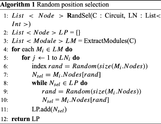
Random: The idea of placing locking gates in random positions is similar to the idea of position selection proposed in [34]. As described before, the simplest method of key gates insertion is placing the key gates randomly in the circuit. The algorithm is presented in Algorithm 1.
-
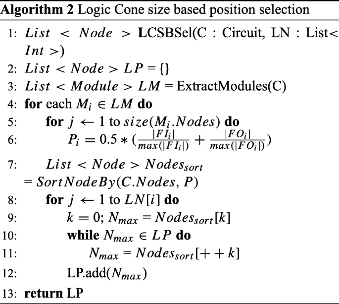
Logic cone size based (LCSB): The concept behind this method is to place keys in the largest logic cones so they will impact more signals. The position with the largest logic cone has been calculated by measuring and comparing a weighted normalized metric for all gates in the module under consideration. This metric was defined in [28] (as presented in Eq. 1) for similar purpose. The metric considers both the fanin and fanout cones of a gate. Gates with higher value of this metric have larger fanin or fanout cone or both and are chosen to have locking gate in their inputs.
$$ P_{i} = 0.5 * (\frac{|FI_{i}|}{\max(|FI_{i}|)} + \frac{|FO_{i}|}{\max(|FO_{i}|)}) $$(1)The equation is utilized to select the locations for inserting key gates with Algorithm 2. This method does not include any randomness in the selection process, so multiple generation attempts with same parameters result in consistent outputs.
-
Secure logic locking (SLL): To implement SLL, we have minimally modified the algorithm provided by the authors of [48] to work with our insertion tool. In this technique, based on interrelation, the key gates are assigned with different key type categories and each category is assigned a specific weight [48]. The authors provided examples of each type, but did not mention the rules that can define the exact process of the gate categorization. Also, this selection is dependent on the weights that is assigned to each key type, but the literature did not present any direction for the weight distribution. Assigning the weights is left to the imagination of the implementer and varying the weight, selection varies. In our benchmark generation process, we have assigned weight of convergent key type to 10, dominant key type to 5, and isolated key type to 0 (key types are described in [48]). Determination of non-mutable gates and golden pattern requires ATPG tools, and we avoided those for the present version. The implemented algorithm is presented in Algorithm 3.


4.1.3 Insertion Phase
In this phase, the netlist is modified to insert the locking key gates in the selected positions. The Verilog file is firstly analyzed to determine the technology library, input and output, number of modules, number of gates in each module, and hierarchy of modules, and to enlist gates of each module. If necessary, detailed analysis is performed, such as determining the fanin and fanout cones of each gate. Then, the insertion of new gates starts from the module with highest hierarchy to the module with lowest hierarchy. The insertion process varies slightly for XOR and MUX key gates, as for the later, two internal nets must be selected carefully that do not form a combinational loop. Algorithm 4 contains our implemented key gate insertion process (where KI stands for key input).

4.1.4 AntiSAT
To protect the combinational obfuscation from SAT attack, multiple methods have been proposed. AntiSAT [44] is a well-known technique among those. We developed a dedicated tool to perform AntiSAT technique on circuits. It defines a new module with all primary inputs and key inputs of thrice the number of primary inputs. The new module is called from the original circuit, specifically from a selected module. The AntiSAT module implements the logic presented in Section 3 and generates a single bit output that goes in the original circuit to be XORed with a primary output (this is an adaption of the “secure integration” mode of AntiSAT, proposed in [44]). In our AntiSAT-based benchmarks, we have performed hybrid obfuscation, where the circuit is also locked with logic locking techniques. Algorithm 5 provides the technical details about how we implemented the AntiSAT technique. In this algorithm, PI stands for primary input and KI stands for key input.

4.2 Pre-synthesis Obfuscation Benchmark Generation
Pre-synthesis obfuscation follows entirely different tools and processes to perform the locking. The circuit representation and the parameters used are fundamentally different than those of post-synthesis obfuscation. The pre-synthesis obfuscation technique we have implemented to generate our benchmarks is described hereunder.
4.2.1 BDD
BDD-based pre-synthesis obfuscation has been performed with three variations in the selection techniques: first one is random permutation based, second one is to implement SAT resiliency, and the last one is to maximize the entropy of the circuit.
-
SAT inspired: Similar to other SAT-resistant logic locking techniques such as anti-SAT and SARLock, the BDD-based SAT-resistant circuits also ensure that only one wrong key value is ruled out per input pattern. This forces SAT-based attacks [41] to brute force through all possible input patterns to extract the correct keys. To perform the actual locking on a circuit, several output pins of the circuit (and the gates in their transitive fanin cone or TFI) are firstly extracted and converted to their corresponding BDD representation. Iterative ITE operations (as explained in Section 3.3.2) are then applied to the BDD to embed key inputs. The wrong functions implemented on applying the wrong keys are the same as the original function, except at one randomly chosen min-term, where the output is flipped.
-
Random: We also performed random functional locking using BDDs. In this technique, applying wrong key values leads to a cube formed by a random permutation of a random number of primary inputs. Similar to SAT-inspired BDD locking, the random locking was performed on a per-output basis.
-
Entropy driven: We also generated BDD-locked benchmarks where the goal was to increase the overall entropy of the obfuscated circuit. The entropy is a metric that reflects the amount of information contained in a vector (see Section 5.3.2). Algorithm 6 shows the steps performed. The main idea is to selectively lock a few outputs (and gates in their TFI) using key inputs and BDD nodes that have a differential entropy greater than a predefined threshold. Here, differential entropy refers to the entropy of the circuit that results from XORing f (BDD representation of an output cone) with b (an internal BDD node that is part of the BDD B of the entire circuit). This differential entropy metric helps us to select sub-functions that are vastly different in terms of Boolean functionality than the original function f.

5 Evaluation
On all the generated benchmarks, we performed extensive analysis to calculate the overheads, attack resiliency, and metrics. We have selected a few benchmarks to represent the whole set (note that for brevity, we cannot include all results in this paper). This selection includes 72 benchmarks generated by varying the circuit while keeping the key-length fixed, and varying the key length while keeping the circuit fixed, enabling us to observe both the effect of changing key size and circuit parameters. Also, to avoid the effect of randomness of the generation processes on attack resiliency and metrics, we have taken 10 samples for each of the 72 benchmarks, making our sample space consisting of 720 benchmarks. In these samples, we incorporated three BDD-based obfuscation methods (benchmarks built on which are yet to be released) along with the six methods (on which our already released benchmarks are built).
5.1 Overhead
In order to calculate overhead, we synthesized obfuscation benchmarks with GSCLib3.0 library with map effort and area effort set as high in Synopsys Design Compiler. Area, power, and timing overheads of the selected benchmarks are presented in Fig. 10. From the result, we made a few observations:
-
Area overhead for structural logic locking techniques depends more on the key size than on different obfuscation methods. If the key length is same, different locking schemes—SLL, random, and logic cone size -based locking—result in almost same area overhead. For SAT-resilient techniques, there are extra key inputs equal to thrice the number of primary inputs [44]. Also, the block itself occupies extra area. For these reasons, AntiSAT benchmarks have higher area overhead, but similar for different logic locking methods like previous case.
-
Power overhead has only static components and depends largely on each method. The location of the key gate has a significant impact on power overhead as it introduces additional loading on adjacent transistors. If the node where the key gate is inserted has high fanin or fanout, the power overhead increases. AntiSAT hybrid benchmarks have large additional logic and BDD benchmarks contain huge amount of decoy logic for wrong keys. This additional logic draws large amount of static power.
-
Timing overhead depends on the obfuscation methods greatly. For example, SLL and LCSB obfuscation inserts new key gates in the same path as previous ones to increase correlation between them. This results in the formation of new critical paths in the design, or worsening of preexisting ones. As a result, the delay overhead associated with SLL is usually higher.

Overheads of selected obfuscation benchmarks
Note that BDD overheads are quite high, because BDD size depends on the order in which variables (primary inputs) are arranged in the BDD. Since these orders are obtained via heuristics, circuit to BDD conversion usually results in a large number of nodes in the BDD (which are later mapped to MUXes for BDD to Netlist conversion). Where possible, we also tried to use a BDD-based synthesis (BDS) tool [46] to perform further logic optimization on the MUX network. BDD benchmarks generated with c5315 and c7552 (32 and 64 bit key) and all entropy-driven BDD benchmarks (except for the ones generated with c1908) have been optimized with BDS tool. We can see in Fig. 10 that overheads for these benchmarks are less than the ones that are not optimized. However, for most of the benchmarks, we noticed that BDD-based locking almost always results in a much higher power, area, and delay overhead.
5.2 Attack Resiliency
One of the main usage of the obfuscation benchmarks is analyzing attack resiliency of different methods and designs. The existing attacks can be performed to compare the methods in terms of protection offered. Also, new attacks can be performed to show the effectiveness of such over existing ones. In our experiment, we have attacked the obfuscation benchmarks with two well-cited attacks on logic locking techniques that we discussed in Section 3.3.3.
5.2.1 SAT Attack
SAT attack is a functional attack on logic locking. Combinational obfuscation is vulnerable to the attack unless additional SAT-resilient techniques are implemented [41]. We have applied the SAT attack (with the tool the authors provided as open source [42]) on every obfuscation benchmark of the suite. SAT attack on all the hybrid benchmarks (combined with anti-SAT) timed out (where timeout is set as 3 h). The time taken by the attack along with the number of iterations for a selection of benchmarks is presented in Table 2. Note that the number of iterations presented in AntiSAT methods is the expected number of iteration (calculated by the equation presented in [44]) and not experimental. For the BDD benchmarks, the number of SAT iterations will depend on the number of outputs locked and the key length allocated to each output. For example, if we locked 4 outputs, each with a key length of 4, we have in total (24) × 4 = 16 total distinguishing input patterns. Therefore, the SAT tool should resolve the circuit in approximately 16 iterations.
Observations from the SAT attack results are quite clear. Any method without a SAT-resilient technique is vulnerable to SAT attack, where the AntiSAT implemented with such circuit is protected from the attack. AntiSAT BDD obfuscation benchmarks performs better against SAT attack than logic locking based ones, but not as good as AntiSAT benchmarks.
5.2.2 Key Sensitization Attack
Key sensitization attack is based on fault analysis with ATPG tool [25, 48]. The key inputs are set as stuck at faults and ATPG is used to generate pattern to propagate the fault (and thus the switching of key value) to primary outputs. This input pattern can be used to determine the right value of the key, by comparing the result of the locked netlist with the result from an unlocked IC. We implemented the attack partially, with Synopsis TetraMAX [25] and performed the attack on all obfuscation benchmarks. We have implemented the first part of the attack in [48] where the attack only finds out isolated key gates. But we extended the attack by making it iterative. The isolated gate that gets broken in the first iteration is fixed to the correct key value and attack is performed again. Faults on some key gates that could not be propagated to the outputs in the first iteration become vulnerable in the next as the controllability of internal nodes changes. The iterative attack runs until there are no new key gates. We have presented the result of this attack on selected benchmarks in Fig. 11 as percentage of key bits that got deduced correctly. In the best case, we could determine 84% of the keys accurately. We validated the determined key by equivalence checking with the original netlist with ABC tool [6].

Percentage of keys successfully retrieved by key sensitizing attack
We can see in Fig. 11 that BDD obfuscation benchmarks are the only ones that are immune to this attack. In generating these benchmarks, each output is obfuscated with predefined number of keys. For these benchmarks, it is impossible to isolate and observe the effect of each gate separately, making the attack ineffective. Both secure logic locking and cone size-based obfuscation place key gates in a way that makes larger network of locks, resulting in moderate resiliency against key sensitization attack.
Another observation of the results is that, though the percentile looks better for AntiSAT-coupled benchmarks, the number of detected key is similar to the circuit without AntiSAT. Even though the AntiSAT block introduces additional key inputs, it only affects one output bit. So, in the best case, AntiSAT can hamper a single key detection of the original circuit. The fact that all the keys in AntiSAT module are nested together and convergent to a single output port also makes them impossible to isolate. But the percentile appears better because of the increase in total number of keys over which the percentage is calculated.
5.3 Metrics
Hardware metrics are set of deterministic parameters that can represent aspects of the circuit in numeric value. For obfuscation, we have introduced a few metrics that can represent features of obfuscation. Some of those metrics refer to the structural features that cause the obfuscated circuit to behave in certain way, like reconvergence and key structure metric. Other metrics quantify the effect of obfuscation on the functional behavior of the design, like Hamming distance, entropy, and verification failure metric. The metrics can be combined in different ways to derive a global quality metric. The composition of such a metric will be user specific as the weights of each component will vary with design intent and application. We have analyzed these metrics thoroughly and observed the relation of these with other quantifiable aspects of the obfuscated circuit like overhead or attack resiliency. In this section, we present some key findings along with the details of new metrics we have proposed.
5.3.1 Verification Failure
In order to study the impact of logic obfuscation techniques on the corruptibility of designs in more detail than with Hamming distance, we have implemented a verification failure metric. This metric utilizes Synopsys Formality, an industrial-strength equivalence checking tool, to evaluate the functional difference between an unlocked and a locked netlist. The output ports of both netlists are set as “compare points” and the following metric is computed. Similar equivalence checking tools such as Cadence Conformal or Mentor Questa can also be used for the computation.
The first portion of expression (2) (the ratio between number of output ports failing to the total number of output ports undergoing equivalence checking) tells us what proportion of the outputs is being affected by the obfuscation technique. The second portion of the expression (the summation) counts the number of failing patterns produced by Formality for each failed output port. The denominator of 1000 indicates a maximum of 1000 failing points that need to be produced during equivalence checking for each compare point. Thus, with the two portions combined, the metric captures the number of outputs affected as well as the extent to which they are affected by the obfuscation technique. Also, in contrast to differential entropy (discussed in Section 5.3.2) which relies on simulations, the metric uses failing patterns produced as counter-examples by Formality. This guarantees higher coverage, i.e., the failing patterns are more likely to be “discovered”, which is clearly not the case for simulation unless an inordinate number of input vectors is used.
5.3.2 Entropy and Differential Entropy
Entropy, as it specifically relates to Shannon Entropy, measures the amount of information present in a source of data. For a combinational circuit (or equivalently, a Boolean function), entropy relates to the number of distinct outputs that can be produced by the function [24]. For a single output, Boolean function with a probability of logic-1 denoted by P i , the entropy is given by Eq. 3, where the first term stands for entropy of logic-1 and second term stands for entropy of logic-0.
For a multiple output function, the exact entropy is computed by calculating entropy for each possible output vector and summing up the entropies [24]. If probability of an output vector O j is P j , then the entropy H is calculated with Eq. 4, where M is the total number of possible output vectors, for N output function, usually M ≤ 2N.
Since such a calculation is usually prohibitive in terms of computation time (due to the large number of possible output vectors M), a good estimate of entropy for a N output function is given in [24] as:
The entropy expression in Eq. 5 tells us about two aspects of the function:
-
Power: A function with high entropy necessarily has many output values that are possible. This then implies that many transitions between logic-0 and logic-1, or between different output vectors, are also possible. This directly increases the dynamic power consumption of the resulting circuit as a result of the switching.
-
Implications for obfuscation: An obfuscated combinational circuit with maximum entropy (i.e., 1) most resembles a random function, where all output values are equally likely across all possible input values.
The major difficulty in computing entropy comes from accurately computing probability P i . In our experiments, P i is estimated by random vector simulation. We have used Nvect = 10,000 random vectors to (i) perform logic simulation on the circuit, (ii) count the number of logic-1 outputs resulting from the Nvect random vectors for each output, and (iii) divide the output-1 count by Nvect.
In addition, we have also computed a metric we term as differential entropy. In order to compute this metric, a miter circuit is formed by XORing each of the outputs of the unlocked netlists with the corresponding outputs in the locked netlist. After forming the miter circuit, random patterns are applied to the miter circuit (i.e., random primary input patterns as well as random key inputs), and the entropy of the miter circuit is evaluated using Eq. 5. This metric thus captures, on a per-output basis, the proportion of bits that differ between the original and locked netlists, and is useful for quantifying “output corruptibility” induced by the locking technique. It has close similarity with Hamming distance in the miter part, but the logarithmic calculation makes entropy calculation more about the amount of information contained than the amount of differing bits.
In our experiment, we have found a close relation between differential entropy and power overhead (as presented in Fig. 12). The proportionality found is well expected as entropy corresponds to the amount of switching in a circuit and power overhead increases with the switching.

Plot of differential entropy vs power overhead
5.3.3 Reconvergence
Reconvergence is a structural metric that represents the rate of internal signals converging in other nodes. For a particular gate, it is defined as the number of times signals starting from this gate converges at some other gate, divided by the number of total gates in fanout of that particular gate. It was proposed as a metric for VLSI benchmark evaluation in [18]. For the purpose of using the concept for evaluating obfuscation, we have slightly redefined the reconvergence metric. Instead of finding the nodes where signals may converge, we search if the inputs to a certain gate started from a same origin, thereby making it a convergent node. For example, in Fig. 13, let G X be the gate under test whose inputs In1 has fanin A and In2 has fanin B. The 2 common gates in A and B are G1 and G2. Also, G X has fanin C with 5 gates. So, the reconvergence for G X is 2/5. It is a normalized value between 0 to 1.

Reconvergence calculation of a gate
Reconvergence is calculated for each gate of the circuit. We have found that the percentage of gates that are highly reconvergent has direct relation with attack resiliencies. So we defined circuit reconvergence as the percentage of gates that have reconvergence between 0.9 and 1.0.
Figure 14 shows the relation between attack resiliency and circuit reconvergence. In Fig. 14a, percentage of keys detected by our implementation of key sensitizing attack is plotted against reconvergence. As lower percentage of keys getting detected refers to more resilient obfuscation, the inversely proportional relation indicates that more resilient circuits have higher reconvergence and vice versa. High reconvergence means large portion of the signals converge at reconvergent gates, and it is obvious that key gates placed on those converging logic cones would be harder to isolate and detect by key sensitization attack (see Section 5.2.2). Figure 14b shows the plot of verification failure metrics vs reconvergence. The inverse proportionality is because of key distribution and key effect masking. For lower percentage of gates being highly reconvergent, the circuit is more loosely connected, and the keys inserted are spread across the design, each perturbing more signals. Conversely, a higher value of the parameter would indicate large number of gates having high convergence; hence, effect keys placed in those logic cones would have less spread ability, causing the wrong key to alter only a portion of circuit (and hence, less corruptibility).

Plot of reconvergence vs attack resiliencies and verification failure metric
Plots c and d in Fig. 14 display the relation between reconvergence and SAT attack resiliency in terms of attack time and number of iterations, respectively. According to the plots, high reconvergence relates to low SAT attack iteration and time. This phenomena can be explained as SAT attack rules out wrong keys by detecting the effect of the wrong key bit in the primary outputs. Gates close to the outputs are highly reconvergent than gates close to the inputs (as per our computed metric). When key gates are placed in logic cones that converge to a gate close to the outputs, there is more chance that the key’s effect can be observable through the primary outputs. This allows the SAT attack to rule out more keys with less iterations.
5.3.4 Key Structure Metric
Key structure metric is a normalized metric that indicated the structural interconnection between key gates. The connection between key gate pairs is categorized and assigned weights, similar to the assessment in [48], but with extra categories included. The arithmetic mean of these weights is termed as the key structure metric. The categories of key pairs based on the structure of their relative position and the weights we assigned on those to calculate the metric are presented in Fig. 15. In this figure, the fanin cone is shown in blue and fanout in orange. The weights of corresponding type are included in the caption. A key gate is labeled “non-mutable” (with maximum weight) if its value cannot be determined by our implementation of key sensitization attack.

Keycategories used in calculating key structure metric. a Isolated, weight = 0. b Convergent, weight = 10. c Partly convergent, weight = 1. d Dominant, weight = 5. e Partly dominant, weight = 1
5.4 Comparative Analysis
We evaluated existing and proposed metrics for all of the selected 720 samples. Averaging over each obfuscation method provides a deeper insight into the structural changes that occur because of the obfuscation. Comparative representation of these metrics for the methods we have implemented is visualized in Fig. 16. The well-known metric in evaluation of obfuscation, Hamming distance, is found not distinguishable for different methods, which indicates its limitation in relative analysis. On the contrary, proposed metrics (verification failure, differential entropy, reconvergence, and key structure) are found to be more sensitive to variation of methods. This property makes these metrics suitable for comparative analysis of different methods.

Variation of metrics for different methods
We have summarized our findings from the analysis in Table 3. The first three rows shows the comparison of overheads between different methods of obfuscation. AntiSAT benchmarks have high overhead because these benchmarks contain SAT resiliency logic which is quite large compared to the small original circuit. BDD obfuscation benchmarks incur higher area and power overhead because we did not performed the optimization with BDS tool on most of the benchmarks (see Section 5.1).
The fourth and fifth rows in Table 3 represent the comparative attack resiliencies of the methods. For SAT attack, all benchmarks without any SAT-resilient technique are vulnerable. AntiSAT benchmarks are completely resilient against the attack. AntiSAT BDD benchmarks show moderate resiliency against SAT attack (see Section 5.2 for details). For key sensitization attack, only BDD benchmarks are found to be completely resilient.
The last five rows of the table present the comparison of metrics that we propose. The assessment has been done by comparing the average metrics of all benchmarks for each method. Though these metrics vary largely for any specific method, the ranges of value that the metrics can have differ for methods. The table contains relative variation of metrics for different obfuscation methods.
6 Future Directions
While the paper presents a well-chosen set of benchmarks, several different metrics for quantitative comparison of the quality of obfuscation, and extensive analysis of the benchmarks using these metrics, there remain many new opportunities for contribution by the peer researchers. Next, we describe several possible areas where future research can be directed.
-
Metrics: In our analysis, we have seen trends that show how the obfuscation metrics relate to attack resiliencies and other features. But these were drawn from 720 samples (72 different benchmarks, 10 samples each). We need to look deeper into the relations with large number of samples from more benchmarks and inspect relations among multiple metrics simultaneously. In our ongoing work, we plan to perform large-scale characterization of the metrics, optimize, find a global quality metric from multiple qualitative metrics to compare different methods, and utilize the metrics in strengthening obfuscation.
-
Larger circuits: We have worked with ISCAS85 since they are the most widely used benchmark in several VLSI fields. In our future work, we plan to construct large benchmarks tailored particularly for hardware obfuscation. We also plan to work on industrial designs and on how we can make obfuscation feasible for those.
-
BDD benchmarks: The method of modifying BDD for obfuscation appears to be strong against attacks [45]. But because of implementing the BDD in circuit with network of MUXs, the method suffers from high overhead. Future work can focus on optimizing the technique to limit the overhead in acceptable range.
-
Sequential obfuscation: Along with the combinational benchmarks, we are working on benchmarking sequential obfuscation. A new suite of such benchmarks will be published in the near future.
-
Behavioral obfuscation: Most of the proposed obfuscation techniques are based on modification of structural description of a design. Until now, we have worked in netlist representation. We are planning to design an algorithm to perform the obfuscation at the behavioral level. This is more challenging because the representation can include many style and patterns in coding. Also, the effect of obfuscation after synthesis still needs to be evaluated.
-
Combination of multiple techniques: We have implemented each technique individually, as was proposed in corresponding literatures. In our future work, we plan to mix-and-match different techniques and evaluate the effect. It is desirable to find the optimum ratio of mixing more techniques that would give the best resiliency against known and future attacks. By mixing, we refer to choose a portion of the key size to be implemented with one technique and another portion with some other technique and so on, and the ratio of the key sizes is the ratio of mixing. AntiSAT technique is such a system that we have worked on already. We want to similarly combine other methods and observe the resultant resiliency.
-
New obfuscation techniques: Since hardware obfuscation is an active area of research, many different techniques are being regularly proposed. We are working to incorporate as many of those as we can to generate obfuscation benchmarks and evaluate their resiliency against existing and new attacks.
-
Trust-Hub: We welcome researchers to upload their obfuscation benchmarks on Trust-Hub [1] with our suite of benchmarks. It is recommended to include supporting documentation and to follow our naming convention. More benchmarks with different methods will benefit researchers with wider selection and more features to evaluate methods and attacks.
7 Conclusion
With growing interest in hardware obfuscation, it is necessary to have standard obfuscation benchmarks to evaluate and compare various obfuscation techniques and attacks. We have developed the first of such benchmarks. The benchmarks are available on trust-hub.org, and we encourage researchers to use these benchmarks in lieu of arbitrarily generated benchmarks. We have also performed detailed analysis of the benchmarks and developed a few obfuscation metrics in process. These metrics have close relation with attack resiliencies and also, in some cases, overheads. For example, our proposed reconvergence metric is found to be proportional to key sensitization attack resiliency and inversely proportional to SAT attack resiliency. These conclusions will lead our future work to improve the proposed metrics, develop new ones, and utilize the metrics in security assessment.
Notes
In complementary CMOS design, a two-input MUX gate requires more transistors than a two-input XOR/XNOR gate.
References
Forte D, Tehranipoor M (2017) Obfuscation Benchmarks. Trust-HUB.org, Trust-HUB. http://www.trust-hub.org/OBFbenchmarks.php
Alkabani Y, Koushanfar F (2007) Active hardware metering for intellectual property protection and security. In: USENIX security symposium, pp 291–306
Alkabani Y, Koushanfar F, Potkonjak M (2007) Remote activation of ICs for piracy prevention and digital right management. In: IEEE/ACM International conference on computer-aided design, 2007. ICCAD 2007. IEEE, pp 674–677
Amir S, Shakya B, Forte D, Tehranipoor M, Bhunia S (2017) Comparative analysis of hardware obfuscation for IP protection. In: Proceedings of the on great lakes symposium on VLSI 2017. ACM, GLSVLSI ’17, pp 363–368
Barak B, Goldreich O, Impagliazzo R, Rudich S, Sahai A, Vadhan S, Yang K (2012) On the (im)possibility of obfuscating programs. J ACM 59(2):6,1–6,48
Berkeley Logic Synthesis and Verification Group (2004) ABC: a system for sequential synthesis and verification. http://www.eecs.berkeley.edu/alanmi/abc/
Bhatkar S, DuVarney DC, Sekar R (2003) Address obfuscation: an efficient approach to combat a broad range of memory error exploits. In: USENIX Security symposium, vol 12, pp 291–301
Brglez F, Fujiwara H (1985) A neutral netlist of 10 combinational benchmark circuits and a target translator in fortran. In: Proceedings of IEEE Int’l symposium circuits and systems (ISCAS 85). IEEE Press, Piscataway, pp 677–692
Brglez F, Bryan D, Kozminski K (1989) Combinational profiles of sequential benchmark circuits. In: IEEE International symposium on circuits and systems, 1989, vol 3, pp 1929–1934. https://doi.org/10.1109/ISCAS.1989.100747
Business Wire (2017) Inside secure unveils industry’s first root-of-trust solution based on RISC-V processor. https://www.businesswire.com/news/home/20171114006581/en/Secure-Unveils-Industry
Chakraborty RS, Bhunia S (2008) Hardware protection and authentication through netlist level obfuscation. In: Proceedings of the 2008 IEEE/ACM international conference on computer-aided design. IEEE Press, pp 674–677
Chakraborty RS, Bhunia S (2009) Security against hardware trojan through a novel application of design obfuscation. In: Proceedings of the 2009 international conference on computer-aided design. ACM, pp 113–116
Chakraborty RS, Bhunia S (2010) RTL hardware IP protection using key-based control and data flow obfuscation. In: 23rd International conference on VLSI design, 2010. VLSID’10. IEEE, pp 405–410
Chakraborty RS, Bhunia S (2011) Security against hardware trojan attacks using key-based design obfuscation. J Electron Test 27(6):767–785
Collberg C, Thomborson C, Low D (1997) A taxonomy of obfuscating transformations. Tech. rep. Department of Computer Science. The University of Auckland, New Zealand
Contreras GK, Nahiyan A, Bhunia S, Forte D, Tehranipoor M (2017) Security vulnerability analysis of design-for-test exploits for asset protection in SoCs. In: 2017 22nd Asia and South Pacific design automation conference (ASP-DAC). IEEE, pp 617– 622
Corno F, Reorda M, Squillero G (2000) RT-level ITC’99 benchmarks and first ATPG results. Des Test Comput IEEE 17(3):44–53. https://doi.org/10.1109/54.867894
Hutton M, Grossman JP, Rose J, Corneil D (1996) Characterization and parameterized random generation of digital circuits. In: Proceedings of the 33rd annual design automation conference. ACM, pp 94–99
IEEE Std 1735-2014 (Incorporates IEEE Std 1735-2014/Cor 1-2015) (2015) IEEE Recommended Practice for Encryption and Management of Electronic Design Intellectual Property (IP), 1–90. https://doi.org/10.1109/IEEESTD.2015.7274481
Imeson F, Emtenan A, Garg S, Tripunitara MV (2013) Securing computer hardware using 3d integrated circuit (IC) technology and split manufacturing for obfuscation. In: Proceedings of the 22th USENIX security symposium. Washington, pp 495–510
Kahng AB, Lach J, Mangione-Smith WH, Mantik S, Markov IL, Potkonjak M, Tucker P, Wang H, Wolfe G (1998) Watermarking techniques for intellectual property protection. In: Design Automation conference, 1998. Proceedings. IEEE, pp 776– 781
Kocher P, Jaffe J, Jun B (1999) Differential power analysis. In: Advances in cryptology—CRYPTO’99. Springer, pp 789–789
Koushanfar F, Potkonjak M (2007) CAD-based security, cryptography, and digital rights management. In: Proceedings of the 44th annual design automation conference. ACM, pp 268–269
Macii E, Poncino M (1996) Exact computation of the entropy of a logic circuit. In: Sixth Great lakes symposium on VLSI, 1996. Proceedings. IEEE, pp 162–167
Manual SU (2005) TetraMAX ATPG user guide. Version X-200509, pp 249–264
Massad ME, Zhang J, Garg S, Tripunitara MV (2017) Logic locking for secure outsourced chip fabrication: a new attack and provably secure defense mechanism. arXiv:170310187
Mishra P, Tehranipoor M, Bhunia S (2017) Security and trust vulnerabilities in third-party IPs. In: Hardware IP security and trust. Springer, pp 3–14
Narasimhan S, Chakraborty RS, Chakraborty S (2012) Hardware ip protection during evaluation using embedded sequential Trojan. IEEE Des Test Comput 29(3):70–79
Rahman MT, Forte D, Shi Q, Contreras GK, Tehranipoor M (2014) CSST: an efficient secure split-test for preventing IC piracy. In: IEEE 23rd NATW 2014. Johnson City, pp 43–47
Rajendran J, Pino Y, Sinanoglu O, Karri R (2012) Logic encryption: a fault analysis perspective. In: DATE 2012. Dresden, pp 953–958
Rajendran J, Sinanoglu O, Karri R (2013) Is split manufacturing secure? In: DATE 13. Grenoble, pp 1259–1264
Rajendran J, Ali A, Sinanoglu O, Karri R (2015) Belling the CAD: toward security-centric electronic system design. IEEE Trans Comput-Aided Des Integr Circ Syst 34(11):1756–1769
Rostami M, Koushanfar F, Rajendran J, Karri R (2013) Hardware security: threat models and metrics. In: Proceedings of the international conference on computer-aided design. IEEE Press, pp 819–823
Roy JA, Koushanfar F, Markov IL (2008) EPIC: ending piracy of integrated circuits. In: Design, Automation and test in Europe, DATE 2008. Munich, pp 1069–1074
Roy JA, Koushanfar F, Markov IL (2010) Ending piracy of integrated circuits. Computer 43(10):30–38
Shakya B, Asadizanjani N, Forte D, Tehranipoor MM (2016) Chip editor: leveraging circuit edit for logic obfuscation and trusted fabrication. In: Proceedings of the 35th ICCAD 2016. Austin, p 30
Shakya B, Tehranipoor M, Bhunia S, Forte D (2017) Introduction to hardware obfuscation: motivation, methods and evaluation. hardware protection through obfuscation. Springer, chap 1, pp 3–32
Shamsi K, Li M, Meade T, Zhao Z, Pan DZ, Jin Y (2017) AppSAT: approximately deobfuscating integrated circuits. In: 2017 IEEE International symposium on hardware oriented security and trust (HOST). IEEE, pp 95–100
Shen Y, Zhou H (2017) Double DIP: re-evaluating security of logic encryption algorithms. In: Proceedings of the on great lakes symposium on VLSI 2017. ACM, pp 179–184
Skudlarek JP, Katsioulas T, Chen M (2016) A platform solution for secure supply-chain and chip life-cycle management. Computer 49(8):28–34
Subramanyan P, Ray S, Malik S (2015) Evaluating the security of logic encryption algorithms. In: IEEE Intl. symposium on HOST 2015. Washington, pp 137–143
Subramanyan P, Ray S, Malik S (2015) SAT attack tool. https://bitbucket.org/spramod/host15-logic-encryption
Syphermedia (2018) Syphermedia. http://www.smi.tv/
Xie Y, Srivastava A (2016) Mitigating sat attack on logic locking. IACR Cryptology ePrint Archive 2016:590
Xu X, Shakya B, Tehranipoor MM, Forte D (2017) Novel bypass attack and BDD-based tradeoff analysis against all known logic locking attacks. In: International conference on cryptographic hardware and embedded systems. Springer, pp 189–210
Yang C, Ciesielski M (2002) BDS: a BDD-based logic optimization system. IEEE Trans Comput-Aided Des Integr Circ Syst 21(7):866–876
Yasin M, Mazumdar B, Rajendran JJV, Sinanoglu O (2016) Sarlock: SAT attack resistant logic locking. In: IEEE Intl. symposium on HOST 2016. McLean, pp 236–241
Yasin M, Rajendran JJV, Sinanoglu O, Karri R (2016) On improving the security of logic locking. IEEE Trans CAD of Integr Circ Syst 35(9):1411–1424
Yasin M, Mazumdar B, Sinanoglu O, Rajendran J (2017) Security analysis of anti-sat. In: 2017 22nd Asia and South Pacific on design automation conference (ASP-DAC). IEEE, pp 342–347
Funding
This work is supported by Cisco Systems, Inc., NSF under grant CNS 1651701, and AFOSR under award number FA9550-14-1-0351.
Author information
Authors and Affiliations
Corresponding author
Rights and permissions
Open Access This article is distributed under the terms of the Creative Commons Attribution 4.0 International License (http://creativecommons.org/licenses/by/4.0/), which permits unrestricted use, distribution, and reproduction in any medium, provided you give appropriate credit to the original author(s) and the source, provide a link to the Creative Commons license, and indicate if changes were made.
About this article

Cite this article
Amir, S., Shakya, B., Xu, X. et al. Development and Evaluation of Hardware Obfuscation Benchmarks. J Hardw Syst Secur 2, 142–161 (2018). https://doi.org/10.1007/s41635-018-0036-3
Received:
Accepted:
Published:
Issue Date:
DOI: https://doi.org/10.1007/s41635-018-0036-3