
Abstract
There is great variation in the lithology and lamination thickness of composite roof in coal-measure strata; thus, the roof is prone to delamination and falling, and it is difficult to control the surrounding rock when developing roadway in such rock strata. In deep mining, the stress environment of surrounding rock is complex, and the mechanical response of the rock mass is different from that of the shallow rock mass. For composite-roof roadway excavated in deep rock mass, the key to safe and efficient production of the mine is ensuring the stability of the roadway. The present paper obtains typical failure characteristics and deformation and failure mechanisms of composite-roof roadway with a buried depth of 650 m at Zhaozhuang Coal Mine (Shanxi Province, China). On the basis of determining a reasonable cross-section shape of the roadway and according to the failure characteristics of the composite roof in different regions, the roof is divided into an unstable layer, metastable layer, and stable layer. The controlled unstable layer and metastable layer are regarded as a small structure while the stable layer is regarded as a large structure. A superimposed coupling support technology of large and small structures with a multi-level prestressed bearing arch formed by strong rebar bolts and highly prestressed cable bolts is put forward. The support technology provides good application results in the field. The study thus provides theoretical support and technical guidance for ground control under similar geological conditions.
1 Introduction
Coal-measure strata have a typical layered characteristic. In the process of rock formation, owing to the sedimentary environment and geological tectonic movement, the lithology of the roof changes alternately in the vertical direction and structural planes, such as bedding, fissures, and weak interlayers, form a layered roof with a complex structure; that is, a composite roof (Peng and Meng 2002). In the development of a roadway in this type of rock strata, the composite roof has a changeable structure and thus a poor bearing capacity, little resistance to deformation, and high sensitivity to engineering disturbance; therefore, it may sag and delaminate readily. If the method of supporting the roof is improper, there is a high chance of the roof falling, which affects the safety of a coal mine (Hou et al. 2013; Xue et al. 2020; Kang 2021). As a type of roadway that is difficult to support, the roadway with a composite roof has long been a focus of research on roadway support. Hebblewhite and Liu (2004) studied the deformation and failure characteristics and the mechanical response of supporting components of a roadway with laminated weak roof in different stages of service. It is necessary to set a long bolt (6 m or longer) in the primary support to reduce the deformation of the upper strata in roof. Murphy (2016) studied different deformation and failure mechanisms of weak shale roof and put forward corresponding control countermeasures. Kang et al. (2015) studied the control mechanism of rock bolt system in a soft-rock roadway and found that the large deformation of a soft-rock roadway can be controlled using strong rock bolts and highly prestressed cable bolts. Yue et al. (2011) conducted similar simulation experiments to study the failure characteristics of a composite roof roadway, finding that the roof readily delaminates and the floor is prone to heave. Yang et al. (2015) studied the deformation mechanism of chambers with composite roof and adopted a support scheme with strong cable bolts and deep–shallow hole grouting to ensure the stability of the chambers. Zhang et al. (2017a, b) revealed the failure mechanism of a thick composite roof and put forward control countermeasures of primary and secondary load-bearing structures to control roof stability. Gao et al. (2004) studied the law of crack development in the surrounding rock of a roadway having a super-thick composite roof and adopted the combined support of high-strength rock bolts that were fully encapsulated and cable bolts to effectively control the roof. Zhang et al. (2011) analyzed the effects of the weak interlayer position on the deformation and failure characteristics of composite roof and put forward a strengthening control principle and control countermeasures for the surrounding rock. Jiang et al. (2014) expounded the effects of different lithologic compositions of the composite roof on the stability of the roof and classified the hidden danger of roof falling based on an index of whether the cable bolts were broken. Su et al. (2014) established a mechanical model of arch–beam coupling action to control bed separation and the massive roof fall of a roadway with an extra-thick (thicker than 10 m) composite roof.
The stress condition of a roadway deteriorates with increasing mining depth. The mechanical response of the deep rock mass is different from that of the shallow rock mass, and large deformation of the roadway becomes more common and control of the surrounding rock becomes more difficult in the deep mine (Xie et al. 2015, 2019; He et al. 2005; Yang et al. 2017a; Zhao et al. 2018; Sun et al. 2018; Lu et al.2019). The problem of stability control is more serious for a deep roadway with composite roof (Kang et al. 2018; He et al. 2007).
The annual output of coal in China ranks first in the world. In recent years, the consumption of cable bolts has increased greatly with the increase in coal mining depth. Indeed, in some coal mines, cable bolts rather than rebar bolts are installed as primary support. However, the breaking rate of cable bolts in some coal mines is high, and roadway roof fall accidents still occur. At present, there is an urgent need to investigate the failure mechanism and control technology of the surrounding rock of a deep roadway, so as to guarantee safety in deep coal development. The Zhaozhuang Coal Mine, which belongs to the Shanxi Jincheng Anthracite Coal Mining Group, has many geological structures in its mine field, a coal seam that is soft and weak, and a composite roof comprising varying layers of mudstone, sandy mudstone, and coal. The Zhaozhuang Coal Mine is a typical mine having particularly extreme geological conditions. At present, the mining depth of most of the mining districts in the coal mine is more than 500 m, and the main roadways adopt cable bolts as primary support without rebar bolts. Compared with the case for shallow mining (at depths less than 400 m), the breaking rate of cable bolts is higher, the deformation of the roadways is larger, and the phenomena of roof fall and rib spalling are more common. The cumulative length of the roadways repaired every year is approximately 20,000 m, and the maintenance cost of the roadways is thus huge, which seriously affects the safety and continuity of mining.
The present paper takes a deep roadway with composite roof in the Zhaozhuang Coal Mine as a study case. First, typical deformation characteristics of the roadway are obtained from the results of an on-site investigation conducted for a period of 2 years. The deformation and failure mechanisms of the roadway are then discussed. Next, the control principle and support technology of the roadway are put forward. Finally, a field application of the newly proposed support scheme is reported, and the support effect is evaluated.
2 Engineering background
2.1 Geological conditions
The Zhaozhuang Coal Mine belongs to the Shanxi Jincheng Anthracite Coal Mining Group and is located in Zhangzi County, Changzhi City, Shanxi Province of China; see Fig. 1a. The designed annual production capacity of the mine is 8 million tons. At present, the mine mainly mines No. 3 coal, the average thickness of the coal seam is 4.5 m, and the dip angle of the coal seam is approximately 5°. The coal seam is weak and soft and contains many joints and fissures. The No. 3103 roadway with an average buried depth of around 650 m is the main auxiliary transportation roadway in the third mining area, and it is categorized as a roadway of deep mining. The roadway was developed by roadheader within the coal seam with a rectangular cross-section of 5900 mm in width and 4500 mm in height, and it only experienced overburden pressure. The immediate roof has a thickness of 3.6 m and comprises gray-black mudstone and sandy mudstone. The main roof has a thickness of 5.0 m and comprises fine-grained sandstone with plant fossils and siltstone layers in the local region. The roadway roof has a complex structure and is a typical layered composite roof. The immediate floor containing plant fossils is mainly sandy mudstone with a thickness of 7.2 m. The main floor is mudstone with a thickness of 2.1 m, and it is intact. The rock column in the study area is shown in Fig. 1b.

The Location of the coal mine for this study and typical geologic column near the coal seam. a Coal mine location. b Rock column
The self-stabilizing time of a roof is short after a roadway is excavated. If the roof is not supported in a timely manner, separations would develop at bedding planes. At present in the study case, only cable bolts are used to support the roadway. The roof cable bolt is a high-strength steel strand with 19 wires. The roof cable bolt has a diameter of 22 mm and length of 7.4 m, and the anchorage length is 1970 mm. The spacing of roof cable bolts is 1000 mm × 1200 mm, and all bolts are installed vertically into the roof. There are six cable bolts in each row for the roof, and they are connected by steel joists. The type of cable bolt used in the coal rib is the same as the type of cable bolt used in the roof and has a length of 5.4 m and an anchorage length of 1970 mm. The cable bolts are installed horizontally into the coal rib with a pattern of 950 mm × 1200 mm. There are five cable bolts in each row for the coal rib, and they are connected by steel joists. Steel wire mesh is installed together with cable bolts on both the roof and rib for surface control. The roof and ribs of the roadway are sprayed with a concrete layer having a thickness of 150 mm and a uniaxial compressive strength of 20 MPa. The floor shotcrete has thickness of 300 mm and uniaxial compressive strength of 30 MPa. The detailed support pattern using the cable bolts is shown in Fig. 2.

Previous support scheme
2.2 Failure characteristics of the surrounding rock
The composite roof roadway is supported by cable bolts, and the surrounding rock is stable in the initial stage. However, with an increase in roadway service time, the mine pressure of the roadway is becoming increasingly intense, resulting in large deformation affecting the safety of the roadway. An on-site investigation carried out for a period of 2 years revealed the main deformation and failure characteristics of the composite-roof roadway as follows.
-
(1)
The roof sags seriously and the hidden danger of roof fall is great. Figure 3 shows different failure modes of the roadway roof. At some places, roof sag exceeds 1 m, which could potentially cause roof falls. The height of the roof falling is mostly concentrated at 2–3 m. In the place where the roof falls, beddings have developed, the bedding planes are relatively smooth, and the bedding-contact cohesion strength is low. In some areas, the concrete layer is not sprayed in time, and the air of dry–wet circulation in the underground coal mine deteriorates the roof, resulting in weathering and fragmentation. There are many string bags on the roof, reducing the pre-tightening force of cable bolts. The monitoring results show that the pretension of cable bolts in the local region is 40%–50% lower than that in the initial stage, but the load on the cable bolts increases gradually with an increase in roof deformation.
Fig. 3 
Roof deformation and failure modes. a Roof sag. b Massive roof fall. c Weathered roof. d Fractured roof
-
(2)
The coal ribs readily spall, and there is obvious squeezing deformation. Typical failure characteristics of the coal ribs of the large cross-section roadway are shown in Fig. 4. The ribs are ultra-high soft coal, joints and cracks have developed, and the ribs are thus prone to failure with remarkable rheological characteristics. With an increase in the roadway service time, there is greater squeezing deformation of the ribs toward the roadway space. The maximum amount of squeezing of the coal rib exceeds 600 mm, and the surface of the ribs is uneven, which readily leads to the overturning of a cable bolt plate and imposes a damaging bending moment on the bolts. It is common for the cable bolts to bend and break at the opening of the plates, as shown in Fig. 4d.
Fig. 4 
Deformation characteristics of coal ribs. a Highly fractured coal. b Coal rib squeezing. c Uneven coal rib. d Heavily loaded cable plate
-
(3)
Support components are seriously damaged and the roadway repair rate is high. Figure 5 illustrates the damage characteristics of roadway supporting components. After large deformation of the roadway, failure often occurs when the supporting components cannot adapt to the deformation. The breaking rate of cable bolts is high. The tearing phenomenon of the shotcrete is common owing to the large non-uniform deformation of the ribs, as shown in Fig. 5b. The roadway has to be repaired and reinforced after it undergoes large deformation, and the main measures adopted are supplementary cable bolts, high-density standing support, and timber chocks. However, phenomena, such as the flexure failure of steel beams, bending of U-shaped steel legs, and breaking of many timber props, are common. The roadway maintenance cost is greatly increased by the requirement for a huge amount of roadway repair work.
Fig. 5 
Damage to supporting components and roadway repair. a Fractured cable bolts. b Shotcrete tear. c High-density standing support. d Broken timber props


2.3 Determination of the roof internal structure
Determination of the failure mechanism of the composite roof requires a comprehensive understanding of the rock structure of the composite roof and the development law of the internal joints and cracks. A 32 mm diameter scope hole was drilled to 10 m deep into the roof at the center of the roadway, and a video scope was used to view and analyze the internal structure of the composite roof. The obtained roof internal structure is shown in Fig. 6.

Images of roof internal structure
The results obtained for the internal structure of the roof reveal that the bedding is well developed and the integrity of the roof is poor, with there being mostly discontinuous failure, at a distance of 0–6.5 m from the roof surface. The phenomenon of bed separation is more obvious in the shallow part of the roof (in the range of 0–1.5 m), and the laminations are thin, most having a thickness of approximately 0.15–0.25 m. At a distance of 1.5–6.5 m from the roof surface, there are many layers of weak argillaceous interlayer, which readily disintegrates and breaks up in the presence of water. The position of maximum separation in the roof is 2.8 m from the roof surface. The longitudinal cracks of the roof are well developed in the range of 3.3–4.5 m. There is a coal line with a thickness of approximately 0.4 m at a distance of 6.0 m from the roof surface. The roof is intact above 6.5 m of the roofline.
3 Failure mechanism of the roadway with composite roof
Field investigation characterized the roadway roof as a special type of layered composite roof having thin laminations, bedding contacts with low cohesion strength, and weak interlayers. The main factors affecting the deformation and failure of the deep roadway with composite roof are summarized as follows.
-
(1)
The engineering geological conditions are complex and the strength of the surrounding rock is low. For the large-cross-section composite-roof roadway with a buried depth of around 650 m, the stress condition of the surrounding rock deteriorates under the effects of the dead weight stress and tectonic stress. The overall strength of the surrounding rock is relatively low owing to the complex geological conditions, bedding and fracture development, local weak interlayers, and soft coal ribs. In a state of high stress, the roof and ribs must have large deformation characteristics (Gao et al. 2015).
-
(2)
The roof geology varies considerably, and the roof delaminates at a fast rate. The coal seam roof has typical characteristics of a layered composite, as shown in Fig. 7, because the coal-measure strata are sedimentary rock affected by the sedimentary environment and tectonic movement in different geological periods. The strength, thickness, and lithologic combination of the layered roof and mechanical properties of bedding planes affect the degree of roof deformation. When the laminations are thin and weak, the deformation capacity of the roof is large and the flexural sag is serious (Coggan 2012). Owing to the changeable structure of the composite roof and the deformation of each lamination being different, the number of bedding separation increases, and the risk of roof fall increases. As the weak part of the composite roof, the weak interlayer is more readily affected by the excavation disturbance, resulting in failure along the interlayer, and this is also the main location where separation occurs (Zhang et al. 2011; Huang et al. 2012). When there are many weak interlayers, the roof is more discrete and thus less able to resist deformation and failure. In particular, uncertainty in the number and positions of weak interlayers leads to discontinuous failure of the roof, which makes it more difficult to prevent the roof from falling.
Fig. 7 
Composite roof with thin laminations revealed during picking roof on site. a Combination characteristics of rock strata within 1 m of the roof. b Broken sandy mudstone interlayer. c Argillaceous shale interlayer
-
(3)
The coal ribs are soft and weak, and it is thus difficult to provide an effective bearing for the roof. The coal ribs are used as the carrier of the roof rock beam. After excavation, the coal rib is unloaded in the lateral direction but loaded in the vertical direction because of the stress concentration. The coal rib is prone to compression–shear yield failure, and the plastic failure range is increased. Tensile failure and the spalling of coal ribs readily occur when joints and cracks of the coal rib have developed (Wang 2007). The roadway is tall in that the height of the coal rib of the roadway is 4.5 m, and the coal rib is thus prone to failure. The coal rib presents three failure modes in the field: compression–shear slip-type, vertical spallation-type, and squeezed hourglass-type failure modes (as shown in Fig. 8). The failure of the coal ribs results in much loss of the load bearing area for the roof. As a result, the sagging deflection of the roof increases, which destabilizes the roof.
Fig. 8 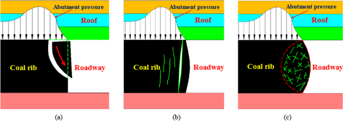
Coal rib failure modes. a Compression–shear slip-type mode. b Vertical spallation-type mode. c Squeezed hourglass-type mode
-
(4)
The mudstone in the roof readily weathers and breaks, and the pretension loss of cable bolts is serious. The mudstone in the roof contains a high-clay mineral as a moisture-sensitive material having poor resistance to water and a humid environment (Yang et al. 2017b; Osouli and Bajestani 2016). In the process of excavation, the development of the roadway was pursued too rapidly, and the surrounding rock in some areas was not sprayed in time. Under the action of dry–wet circulating air or local roof dripping in a coal mine, the mudstone is prone to weathering, disintegration, and then breaking up into blocks of different size, as shown in Fig. 9. The weathering of mudstone could loosen the cable bolt plates, resulting in a loss of pretension in the bolts, and thus reducing the active control of the surrounding rock and increasing the risk of roof falls.
Fig. 9 
Test results for a dry–wet cycle of immersed mudstone
-
(5)
The performance of the previous support scheme is poor, and the bearing capacity of the surrounding rock itself is low. After the roadway was excavated, the composite roof was supported by cable bolts of the same length installed at the same horizon of the roof by means of end anchoring. The cable bolts can be tensioned with higher pretension, which has a good control effect for the early deformation and separation of the roof. The service interval of the main roadway is generally more than 3 years. In the case of a roadway having a long service interval, an underground humid environment degrades the mechanical properties of the rock mass and cable bolts. Furthermore, the support level of cable bolts in the roof is single, the composite roof is more likely to sag and separate, and the active control effect of cable bolts on the rock mass above the separation position is greatly reduced, as shown in Fig. 10a.
Fig. 10 
Cross-section of the roadway showing buckling of the roof associated with cutter formation, bed separation, and fractured cable bolts. a Roof buckling. b Roof cutter. c and d Fractured cable bolts


The results of the field investigation show that while the composite roof sags and separates, the upper corners on the two sides of the roadway are damaged by stress concentration. This form of failure, illustrated in Fig. 10a, is often known as cutter roof failure. With the development of the flexure of the composite roof, the fracture propagates upward at a certain angle from the horizontal (where field statistics show that the angle is generally between 60° and 70°, as shown in Fig. 10b) until it reaches a relatively strong layer that prevents the failure from propagating further (Gadde and Peng 2005; Murphy 2016; Gao 2013). At the same time, an increasing dead load of rock rests on the cable bolts, resulting in the breaking of many cable bolts, as shown in Fig. 10c and d. If the supporting strength of the roof is insufficient, there is buckling instability of the composite roof. In the field, supplementary cable bolts, high-density standing support, and timber chocks are often used to support an area in which there is large deformation, but the supporting effect is poor. This is mainly due to the fact that internal separation and failure of the roof have occurred, most secondary supporting components are in a passive bearing state, and the bearing capacity of the surrounding rock without an effective constraint is generally low.
4 Measures for controlling the surrounding rock
4.1 Principle of controlling deformation of a roadway with composite roof
The essence of roadway support is to use different supporting components, combined with key technical parameters, to improve the stress state and mechanical properties of the surrounding rock. The supporting components form a mutually coordinated and interactive bearing system with the surrounding rock, which can maximize the bearing capacity of the surrounding rock itself (Yang 2017a, Yang 2017b). In an effort to fully clarify the failure mechanism of a deep roadway with composite roof, the shape of the roadway section is optimized and effective control countermeasures for the surrounding rock are put forward. Consideration is given to the following aspects.
-
(1)
The shape of the roadway section should be able to bear a force uniformly and avoid the local concentration of stress. The shape of the cross-section of the roadway affects the stress state of the surrounding rock. In the case of a rectangular roadway, stress concentration at the upper corner of the roadway readily causes cutter roof failure, which is not conducive to the control of the surrounding rock. The stress acting on the surrounding rock of a circular roadway is relatively uniform, which is conducive to stabilization of the surrounding rock, but the construction of a circular roadway is difficult, and a semicircular arch roadway or circular arch roadway is thus used instead.
-
(2)
Different supporting components should be able to coordinate with each other and complement each other. When selecting the supporting patterns of a roadway, we should adhere to the principle of “a combination of long and short, a combination of stiffness and deformability, and a combination of sparse and dense”, and take full advantage of the superior performance of each supporting component. If the coordinated support of rebar bolts and cable bolts is adopted, the high elongation of a rebar bolt and the high bearing capacity of a cable bolt complement each other. By reasonably optimizing the anchorage length of the bolts and increasing the pretension, the coordinated support of rebar bolts and cable bolts can take full advantage of strong initial support, a rapid increase in resistance, and a high working resistance to strengthen the control of various discontinuous structural planes and weak interlayers in the roof and effectively improve the mechanical properties of the surrounding rock. Furthermore, the active control of the surrounding rock can be improved and the bearing capacity of the deep stable surrounding rock can be fully used.
-
(3)
Adhering to the principle of “coordinated control of the roof and ribs”, for a large-cross-section roadway with composite roof, in strengthening the roof, the support strength of coal ribs must be ensured. The stability of the coal ribs, as the effective carrier of the roof, directly affects the effective span of the roof. Coal ribs in the field are tall, weak, and soft, and the supporting strength of the ribs should therefore be properly improved to provide an effective bearing of the roof. The load acting on the coal ribs is less when the roof is stable, which is beneficial to the maintenance of the ribs.
-
(4)
The roadway mine pressure behavior should be recorded and analyzed. A database for the deformation of surrounding rock throughout the mining area or for a certain type of roadway is created by collecting a large number of data. Such a database is useful in the analysis of the instability mechanism of the surrounding rock and the selection of support modes. Dynamic design and construction should be adhered to in roadway support design. Once the supporting measures adopted for the composite-roof roadway are completed, a station should be set up in a timely manner for the continuous monitoring of the mine pressure. We can improve the preliminary support design through the timely feedback of the main indicators of monitoring.
4.2 Superimposed coupling support technology of large and small structures
A reasonable cross-section shape of the roadway effectively reduces local stress concentration and avoids large-scale plastic failure of the surrounding rock, thus reducing the difficulty of implementing supporting measures (Meng et al. 2012; Li et al. 2010). To reduce the adverse force on the composite roof and considering the difficulty of constructing roadways with different cross-sections, the rectangular cross-section of the roadway is optimized as a circular-arch cross-section, which effectively prevents cutter roof failure (Li et al. 2017). The newly designed roadway with a circular-arch cross-section has a width of 5.9 m and height of 4.5 m. The vertical ribs of the roadway are arranged in the coal seam with a height of 2.7 m. The height of the circular arch is 1.8 m, all of which are arranged in the roof of the coal seam.
After the circular-arch roadway with composite roof is excavated, owing to differences in mining disturbance, the roof has different degrees of failure at different depths (Yang et al. 2017b). According to the degree of fracture of the surrounding rock, the roof can be divided into a broken zone, cracked zone, and intact zone. The rock mass has a different bearing capacity in each zone, corresponding to an unstable layer, metastable layer, and stable layer, as shown in Fig. 11a.

Schematic diagram of the principle of controlling the surrounding rock. a Roof with different zones. b Supporting stress field without field stress generated by support components
The unstable layer is located in the shallow part of the surrounding rock. The unstable layer readily falls and has a low bearing capacity owing to the disturbance caused by excavation unloading. The metastable layer is mainly located in the middle part of the composite roof and has secondary fissures that are more developed, but a low degree of crack penetration. The metastable layer still has a certain bearing capacity. When the support strength is insufficient, the metastable layer readily transforms into the unstable layer, which increases the range of the unstable layer and the difficulty of controlling the surrounding rock. The stable layer is located in the deep part of the roof, which is less disturbed by excavation, and it is in an elastic state and has good bearing capacity.
For the composite-roof roadway, the load borne by the supporting structure mainly comprises a given load and a deformation load (Zhang and Chen 2016). The unstable layer mainly produces a loose load, which belongs to the category of “given loads”. The deep stable layer has good integrity and thus high bearing capacity, and its load effect on the supporting structure belongs to the category of “deformation loads”. In the case of the central metastable layer, the load of the supporting structure is not only a given load but also a deformation load.
In ensuring the stability of the composite roof, it is necessary to control the unstable layer in the shallow part of the roof and the metastable layer in the middle part and make full use of the bearing capacity of the deep stable layer itself. From the above point of view, the deep stable layer can be regarded as the “large structure” of the surrounding rock, whereas the unstable layer and metastable layer as a whole can be regarded as the “small structure” of the surrounding rock (Fig. 11a). To elucidate the deformation and failure mechanisms of a deep large-cross-section roadway with composite roof, the superimposed coupling support technology (SCST) of a large structure and small structure is put forward in this paper. The central concept of this technology is “sealing the surrounding rock, strengthening the small structure, and making full use of the large structure” with shotcrete, strong rebar bolts, and highly prestressed cable bolts. The control principle of the composite roof is illustrated in Fig. 11.
The control principle of the SCST with a large structure and small structure for the deep composite-roof roadway is mainly reflected in terms of multi-level support. The first level is the airtight shotcrete. In ensuring the stability of the support system, it is necessary to strengthen the control of the surrounding rock at the position of the roof surface. A concrete layer is sprayed in a timely manner to isolate the surrounding rock from air and water, prevent the surrounding rock from weathering and disintegration, and minimize the adverse effects of deterioration of the rock mass strength. The supporting plates of bolts, steel bar beams, and metal mesh match each other, which effectively spreads the prestress of bolts on the roadway surface and ensures the surface surrounding rock is in a state of three-dimensional stress with uniform pressure support.
The second level is the strong rebar bolts, which mainly control the unstable layer. The unstable layer located in the shallow part of the surrounding rock poses a great hidden danger of roof fall, which is the focus of control. We must ensure that the strong bolt extends beyond the boundary of the unstable layer and increases the pretension of the rebar bolts. After the strength and stiffness of the support system are improved, the separation of the roof can be restrained, and a stable pressure-bearing arch can be formed (shown in Fig. 11b). This promotes the transformation of the rock mass in this area from a given load to a deformation load.
The third level is the highly prestressed cable bolts of reasonable length, which can be anchored in the stable layer. We should take full advantage of the fact that the cable bolts can be tensioned with a large pretension to form a large-scale bearing arch (shown in Fig. 11b), such that the unstable layer, metastable layer, and stable layer form a continuous carrier. By applying highly prestressed cable bolts to strengthen the control of the unstable layer which is easy to generate large discontinuous deformation, the metastable layer of the middle part of the roof is constrained, and the small structure of surrounding rock as a whole is thus strengthened. The highly prestressed cable bolts impose radial constraints on the deep stable layer at the same time, the bearing capacity of the deep stable layer will be fully used, and form a continuous prestressed bearing structure. The superimposed large and small structures thus form a unified support system, which ensures the stability of the composite roof.
It is noted that the two ribs of the deep composite roof roadway comprise weak and soft coal and they are prone to unravel. Therefore, the support strength of the coal ribs must be ensured to avoid large-scale spalling and squeezing, and to ensure that the coal ribs provide an effective bearing for the roof. Hence, we should adhere to the principle of “the cooperative control of roof and ribs” in supporting a deep roadway with composite roof.
5 Field application and analysis
5.1 New support scheme
The cross-section of main roadway 3103 was optimized as a circular arch, and the SCST of large and small structures was adopted. The following detailed support parameters were determined based on engineering geological conditions of the roadway, adopting the engineering analogy method and numerical simulation analysis (Li 2006, 2017; Jiang et al. 2019; Zhang et al. 2017a, b).
-
(1)
Roof support
High-strength bolts with yield strength not less than 500 MPa are used for roof support. The rebar bolts are 22 mm in diameter and 2.4 m in length. The spacing of rebar bolts is 900 mm × 1000 mm, and each bolt is anchored with fast–slow resin cartridges to ensure that the anchoring length is not less than 1500 mm. The pretension force applied during rebar bolt installation is not less than 70 kN. Cable bolts, each having 19 steel wires, are used for roof support. The ultimate tension of a cable bolt is not less than 550 kN. The spacing of cable bolts is 1800 mm × 2000 mm. There are three cable bolts for each row in the roof. The anchorage length of cable bolts is not less than 2000 mm, and the pretension force is not less than 250 kN. A metal mesh is used in addition to the rebar bolts and cable bolts for roof support. The metal mesh comprises steel bars with a diameter of 6.5 mm, and the cell dimensions are 100 mm × 100 mm.
-
(2)
Rib support
Ribs are supported by rebar bolts, cable bolts, and metal mesh. The bolt and mesh types are the same as those used for the roof. The spacing of rebar bolts is 800 mm × 1000 mm. Four bolts are arranged in each row of one coal rib. The anchoring length of the rebar bolts is not less than 1500 mm, and the pretension force is not less than 70 kN. The cable bolts have a diameter of 22 mm and length of 5.4 m. The distance between cable bolts is 1200 mm, the row separation is 2000 mm, the anchorage length is not less than 2000 mm, and the pretension is not less than 150 kN. The metal mesh comprises steel bars with a diameter of 6.5 mm, and the cell dimensions are 100 mm × 100 mm.
-
(3)
Shotcrete
After the installation of rebar bolts and cable bolts, a concrete layer with thickness of 150 mm and uniaxial compressive strength of 20 MPa is sprayed on the roof and ribs of the roadway. The shotcrete applied to the floor has a thickness of 300 mm and a uniaxial compressive strength of 30 MPa.
The detailed parameters of different support components are presented in Fig. 12. Figure 12a shows detailed arrangement parameters of rebar bolts and cable bolts in the roadway cross-section, while Fig. 12b shows the arrangement of rebar bolts and cable bolts along the axial direction of the roadway.

Schematic diagram of the new support design. a Support design in the roadway cross-section. b Three-dimensional schematic diagram of the support scheme
5.2 Analysis of the support effect
During roadway excavation, construction was carried out in strict accordance with the newly designed support scheme. In comprehensively evaluating the control effect of the new support scheme on the surrounding rock, three measuring stations were set up at intervals of 50 m to monitor the mine pressure behavior of the roadway. The main items of mine pressure monitoring were the roof sag, rib-to-rib convergence, and axial load of bolts. At the same time, internal bed separation and crack development in the roof were detected using a borehole imaging analyzer, and the cable bolts were checked to see whether they had broken. The instruments used in the monitoring were arranged at the measuring stations on site, as illustrated in Fig. 13.

Instruments used in on-site monitoring
The variation curve of the roadway surface displacement with time is obtained by sorting the relevant monitoring data (Fig. 14). The trend of the axial load curves of bolts with time is almost the same at different stations, and only the axial load curve of bolts for one station are thus used for analysis, as shown in Fig. 15.

Measured deformation during the roadway development. a Roof sag. b Rib-to-rib convergence

Measured axial load of bolts during the roadway development. a Rebar bolts. b Cable bolts
Figure 14 shows that the deformation of surrounding rock tends to become stable after 40 days of roadway excavation, the maximum subsidence of the roadway roof is 68 mm, and the maximum convergence between two ribs is 140 mm. Overall, the deformation of the roadway surface is small. Figure 15 shows that with time, the axial load of bolts increases gradually and finally tends to stabilize, which is consistent with the increasing trend of deformation of the surrounding rock. The maximum axial loads of rebar bolts and cable bolts are lower than the ultimate loads. The axial load of rebar bolts and cable bolts rise synchronously, and the coordinated support and cooperative bearing of rebar bolts and cable bolts are realized. However, the increase in the axial load of the cable bolts is not appreciable, indicating that the bolts with higher pretension have a good control effect on the discontinuous deformation of the roof in the anchorage range, such as the bed separation, shearing along bedding planes, and the opening of internal fissures, which is conducive to the superposition and coupling of large and small structures. The support scheme can make full use of the bearing capacity of the surrounding rock itself and ensure the stability of the surrounding rock during the service period.
After 12 months of roadway excavation, the borehole imaging analyzer was used to detect the development of separation and cracks in the roof. Results are presented in Fig. 16.

Internal structure of the roof after adopting the new support scheme
Figure 16 shows no obvious separation in the roof or appreciable cracking at the position of the weak interlayer, which further shows that the SCST of large and small structures effectively controls the evolution of separation and cracks in the composite roof. The multi-level support eliminates the discontinuous failure of the composite roof.
The field investigation was carried out for a roadway service time longer than 18 months. Except for the small cracks in the local shotcrete of the coal rib, there was no abnormal large deformation and the overall stability was good. A tension test carried out for a large number of cable bolts did not find broken cable bolts.
The above analysis reveals that the new support scheme has a good control effect on the surrounding rock of a deep-large cross-section roadway with composite roof. This study provides a successful example for roof support under similar geological conditions.
6 Conclusions
The purpose of this paper was to fully clarify the deformation and failure mechanisms of a deep composite-roof roadway with cable bolts as the primary support under particularly extreme geological conditions, and to put forward reasonable control measures for the surrounding rock. Theoretical support and technical guidance were thus provided for the stability control of a roadway under similar geological conditions. The main conclusions of the paper are as follows.
-
(1)
Through on-site investigation, the composite roof was characterized by thin laminations, bedding contacts with low cohesion strength, and weak interlayers. The typical failure characteristics of a deep roadway with composite roof are severe roof subsidence and a great hidden danger of roof fall; the coal ribs readily spall and there is obvious squeezing deformation; and the supporting components are seriously damaged and the roadway repair rate is high.
-
(2)
The low strength of the surrounding rock, changeable roof structure, soft and weak coal ribs, serious loss of pretension of cable bolts, and poor effectiveness of the support scheme are the main factors affecting the deformation and failure of the deep roadway with composite roof.
-
(3)
Realizing the effective control of the surrounding rock under these particularly extreme geological conditions requires the reduction of the adverse force by optimizing the cross-section of the roadway, adoption of supporting components that complement each other, and cooperative control of the roof and ribs. More importantly, the support design should be dynamically adjusted according to mine pressure monitoring of the roadway.
-
(4)
On the basis of the failure mechanism of the composite roof, and from the point of view of regulating the load effect of the surrounding rock, the superimposed coupling support technology of large and small structures with strong rebar bolts and highly prestressed cable bolts was put forward, and a good application effect was observed in the field.
References
Coggan J, Gao FQ, Stead D, Elmo D (2012) Numerical modelling of the effects of weak immediate roof lithology on coal mine roadway stability. Int J Coal Geol 90:100–109
Gadde M, Peng SS (2005) Recent advances in numerical simulation of cutter roof failure in underground coal mines. In: Proceedings of the 24th international conference on ground control in mining. West Virginia University, Morgantown, pp 162–168
Gao FQ, Stead D, Kang HP (2015) Numerical simulation of squeezing failure in a coal mine roadway due to mining-induced stresses. Rock Mech Rock Eng 48:1635–1645
Gao FQ, Stead D (2013) Discrete element modelling of cutter roof failure in coal mine roadways. Int J Coal Geol 116:158–171
Gao JH, Kang TH, Jin ZM, Zheng TB (2004) Similar simulation study on crack development law of surrounding rock of roadway with great-thick thin-bedded top roof. Chin J Rock Mech Eng 23(19):3292–3297
Hebblewhite BK, Liu T (2004) Geomechanical behavior of laminated, weak coal mine roof strata and the implications for a ground reinforcement strategy. Int J Rock Mech Min Sci 41:147–157
He MC, Xie HP, Peng SP (2005) Study on rock mechanics in deep mining engineering. Chin J Rock Mech Eng 24(16):2803–2813
He MC, Qi G, Cheng P, Zhang GF, Sun XM (2007) Deformation and damage mechanism and coupling support design in deep coal roadway with compound roof. Chin J Rock Mech Eng 26(05):987–993
Hou CJ et al (2013) Ground control of roadways. China University of Mining and Technology Press, Xuzhou
Huang F, Zhu HH, Xu QW, Cai YC, Zhuang XY (2012) The effect of weak interlayer on the failure pattern of rock mass around tunnel - Scaled model tests and numerical analysis. Tunn Undergr Sp Technol 35:207–218
Jiang LS, Ma NJ, Bai L, Li YJ, Zhang L (2014) Deformation and failure characteristics and roof caving hidden danger classification of roadways compound roof. J Chin Coa Soc 39(07):1205–1211
Jiang LS, Kong P, Shu JM, Fan KG (2019) Analysis of support designs based on a case study of a longwall entry. Rock Mech Rock Eng 52:3373–3384
Kang HP (2021) Seventy years development and prospects of strata control technologies for coal mine roadways in China. Chin J Rock Mech Eng 40(01):1–30
Kang HP, Lin J, Fan MJ (2015) Investigation on support pattern of a coal mine roadway within soft rocks–a case study. Int J Coal Geol 140:31–40
Kang HP, Wang GF, Jiang PF, Wang JC, Zhang N, Jing HW, Huang BX, Yang BG, Guan XM, Wang ZG (2018) Conception for strata control and intelligent mining technology in deep coal mines with depth more than 1000 m. J Chin Coa Soc 43(7):1789–1800
Li CC (2006) Rock support design based on the concept of pressure arch. Int J Rock Mech Min 43(7):1083–1090
Li CC (2017) Principles of rockbolting design. J Rock Mech Geotech 9(3):396–414
Li GC, Zhang N, Wang C, Zhang NC, Li BY (2010) Optimizing the section shape of roadways in high stress ground by numerical simulation. J Chin Univ Min Tech 39(05):652–658
Li YL, Lei YJ, Zhao Y, Xiao CL (2017) Optimization and support technology for coal roadway cross-section in weak cemented stratum. Chin Coa 43(02):33–37
Lu W, Wang Q, Jiang B, Xu S, Liu BH, Zhang P (2019) Comparative study on bearing mechanism and design parameters of confined concrete arch joints in deep soft rock roadway. Int J Coal Sci Technol 6(4):493–504
Meng QB, Han LJ, Qiao WG, Lin DG, Wei LC (2012) Numerical simulation of cross-section shape optimization design of deep soft rock roadway under high stress. J Min Safe Eng 29(05):650–656
Murphy MM (2016) Shale failure mechanics and intervention measures in underground coal mines: results from 50 years of ground control safety research. Rock Mech Rock Eng 49:661–671
Osouli A, Bajestani BM (2016) The interplay between moisture sensitive roof rocks and roof falls in an Illinois underground coal mine. Comput Geotech 80:152–166
Suping P, Zhaoping M (2002) Theory and practice of mining engineering geology. Geological Publishing House, Beijing
Sue XG, Song XM, Li HC, Yuan HH, Li BK (2014) Study on coupled arch-beam support structure of roadway with extra-thick and soft compound roof. Chin J Rock Mech Eng 33(09):1828–1836
Sun XM, Chen F, Miao CY, Song P, Li G, Zhao CW, Xia X (2018) Physical modeling of deformation failure mechanism of surrounding rocks for the deep-buried tunnel in soft rock strata during the excavation. Tunn Undergr Sp Technol 74:247–261
Wang JC (2007) Mechanism of the rib spalling and the controlling in the very soft coal seam. J Chin Coa Soc 32(08):785–788
Xie HP, Gao F, Ju Y (2015) Research and development of rock mechanics in deep ground engineering. Chin J Rock Mech Eng 34(11):2161–2178
Xie HP, Gao MZ, Zhang R, Peng GY, Wang WY, Li AQ (2019) Study on the mechanical properties and mechanical response of coal mining at 1000 m or deeper. Rock Mech Rock Eng 52:1475–1490
Xue DJ, Zhou J, Liu YT, Gao L (2020) On the excavation-induced stress drop in damaged coal considering a coupled yield and failure criterion. Int J Coal Sci Technol 7(1):58–67. https://doi.org/10.1007/s40789-020-00299-z
Yang RS, Li YL, Guo DM, Zhu Y, Yao L, Yang TM, Yu XT (2017a) Deformation reasons and support technology of deep and high-stress soft rock roadway. J Min Safe Eng 34(06):1035–1041
Yang RS, Li YL, Guo DM, Yao L, Yang TM, Li TT (2017b) Failure mechanism and control technology of water-immersed roadway in high-stress and soft rock in a deep mine. Int J Min Sci Technol 27(2):245–252
Yang RS, Xue HJ, Guo DM, Li YL, Li TT, Xue JZ (2015) Failure mechanism of surrounding rock of large section chambers in complex rock formations and its control. J Chin Coa Soc 40(10):2234–2242
Yue ZW, Yang RS, Yan ZD, Zhang YH, Han PF (2011) Experimental study on stability of surrounding rock of coal roadway with compound roof and large cross section. J Chin Coa Soc 36:47–52
Zhang DL, Chen LP (2016) Compound structural characteristics and load effect of tunnel surrounding rock. Chin J Rock Mech Eng 35(03):456–469
Zhang N, Li GC, Kan JG (2011) Influence of soft interlayer location in coal roof on stability of roadway bolting structure. Roc Soi Mech 32(09):2753–2758
Zhang GC, He FL, Jia HG, Lai YH (2017a) Analysis of gateroad stability in relation to yield pillar size: a case study. Rock Mech Rock Eng 50(05):1263–1278
Zhang JW, Yuan RF, Li YL (2017b) Research on surrounding rock control of coal roadway with thick mudstone compound roof. Chin J Rock Mech Eng 36(01):152–158
Zhao TB, Guo WY, Tan YL, Yin YC, Cai LS, Pan JF (2018) Case studies of rock bursts under complicated geological conditions during multi-seam mining at a depth of 800 m. Rock Mech Rock Eng 51(5):1539–1564
Acknowledgements
This study was supported by the National Natural Science Foundation of China (No. 51804310; No. 52074301) and Fundamental Research Funds for the Central Universities (No. 2020XJNY05).
Author information
Authors and Affiliations
Corresponding authors
Additional information
Publisher's Note
Springer Nature remains neutral with regard to jurisdictional claims in published maps and institutional affiliations.
Rights and permissions
Open Access This article is licensed under a Creative Commons Attribution 4.0 International License, which permits use, sharing, adaptation, distribution and reproduction in any medium or format, as long as you give appropriate credit to the original author(s) and the source, provide a link to the Creative Commons licence, and indicate if changes were made. The images or other third party material in this article are included in the article's Creative Commons licence, unless indicated otherwise in a credit line to the material. If material is not included in the article's Creative Commons licence and your intended use is not permitted by statutory regulation or exceeds the permitted use, you will need to obtain permission directly from the copyright holder. To view a copy of this licence, visit http://creativecommons.org/licenses/by/4.0/.
About this article

Cite this article
Li, Y., Yang, R., Fang, S. et al. Failure analysis and control measures of deep roadway with composite roof: a case study. Int J Coal Sci Technol 9, 2 (2022). https://doi.org/10.1007/s40789-022-00469-1
Received:
Accepted:
Published:
DOI: https://doi.org/10.1007/s40789-022-00469-1