
Abstract
In order to meet engineering needs of Chinese underground coal mines, a new dust-collecting fan, a device of dust separated by centrifugal force in driven cyclone passageway (DCCP) was designed. In centrifugal dust removal section (CDRS) of DCCP, a general equation is derived from the principle of force equilibrium. According to CDRS structure parameters and fan running parameters, the general equation is simplified, and the simplest equation is calculated numerically by MATLAB. The calculation results illustrate that increasing quantity of air current is against dust removal, but it is beneficial to dust removal by increasing the radius of driven spiral blade and increasing the particle diameter of coal dust. The conclusions show that the dust-collecting structure parameters coupled with the fan running parameters is a novel optimization approach to dust-collection fan for working and heading faces, which is especially suitable for Chinese underground mines.
1 Introduction
It was known that overexposure to airborne respirable dust will cause disabling or fatal respiratory disease, and health problems of coal dust have been an ongoing occupational health concern. As far as Chinese coal mines, it was reported that there was over 2.65 million workers exposure to dust and the pneumoconiosis detection percentage was up to 7.2 %, and the number of accumulated pneumoconiosis patients had been over 57,000 (Zheng 2011). The risks of occupational health of workers, who exposure to coal dust cloud, are directly related to coal metamorphic degree, coal dust concentration, cumulatively exposure time et al. (Naidoo et al. 2005; Belle and Phillips 2009; Onder and Yigit 2009; Qin and Liu 2009; Zhang et al. 2013). For examples, the statistical data from NIOSH (The National Institute for Occupational Safety and Health) indicated that: for USA underground coal mines, the pneumoconiosis detection percentage of workers exposure to coal dust had arisen from 4 % to 9 %, from 1999 to 2007, as the mining intensity increased (Hall 2008). If the pneumoconiosis detection percentage of coal workers can be kept or decreased, the key may be dust isolated and removal in working/heading face, where there usually is the highest concentration of coal dust. In terms of the problem of coal dust pollutant in two faces, the most effective method of pollutant removal may be the dust isolated (or removal) by ventilation and collection by dust catchers (Reed et al. 2004; Guo 2007; Li et al. 2007; Wei 2008; Liu et al. 2009; Liu 2011; Kuznetsov et al. 2012; Li et al. 2012; Liu et al. 2012). The dust catchers employed in underground coal mines, can be classified as filtering, centrifugal separation and comprehensive system (Colinet et al. 2005; Black et al. 2007; Shorokhov et al. 2009; Koo et al., 2010; Faschingleitner and Hoflinger 2011; Torano et al. 2011; Konorev and Nesterenko 2012; Li et al. 2013). For examples, the dust catcher usually applied in German underground coal mines, is usually a fiber bag precipitator, its dust collection efficiency is high and the bulk is also large. In Poland, the main dust catcher is a cyclone dust collector, and its collection efficiency is up to 99.3 %, and the dewatering efficiency is also up to 98 %, but the operating resistance is over 2,300 Pa. The collection efficiencies of the above two dust precipitators are usually higher than 95 %, but they may be not suitable for application in Chinese underground mines. Why is so? In the view of economy to technique ratio and engineering geology, the cross sectional area of heading/mining faces is usually not larger than 15 m2, and the most part is lower than 10 m2, especially underground coal mines in central southern and southwestern China such as Hunan, Guizhou, Yunan, etc. Therefore, the advanced dust precipitators, which are employed in Germany, Poland et al., are in too large bulk or too high operating resistance for the majority of Chinese underground coal mines. Comprehensively analyzing research progress at home and abroad, as far as Chinese underground coal mines, the shortcoming of the existing dust collector is that: (1) the efficiency of dust removal is low (about 80 %), or (2) the dewatering rate is low (lower than 85 %), or (3) the operating resistance is high (more than 2,200 Pa), or (4) the length/width is long/wide (more than 10 m/2.5 m), or (5) the bulks are large.
With consideration on the engineering conditions of Chinese underground coal mines, a novel dust-removal fan based on the studies of home and abroad, named as DCCP was designed.
2 Design of DCCP
DCCP is shown in Fig. 1, and consists of three sections. The first is the fan section, and CDRS is the second section, and the third is the dewatering section.

Sketch of DCCP. 1 the fan, 2 the coupling connection, 3 the extending axis, 4 the driven spiral blade, 5 the water sink, 6 the water baffles, A the polluted air current, B the fan section, D CDRS, E the dewatering section, F the purified air current
Firstly, the polluted air current, which transports coal dust, is driven by the rotating blades of the fan, then, the polluted air current flows into the DCCP. The extending axis connected with the fan axis by coupling connection. The spiral blade is fixed on the extending axis, is followed with rotation if the fan blades rotate. If the spiral blade is rotating, an interesting phenomenon will appear in CDRS of DCCP. The airflow passageway in CDRS is transformed to the cyclone passageway, named as a driven cyclone passageway. Secondly, the polluted air current in CDRS is constrained by the driven cyclone passageway, and the velocity components of air current has axial, radial and tangential, so the air current in CDRS is transformed to a spiral air current. Thirdly, the dust particles are separated from the polluted air current by centrifugal force, and are captured by water sink. Finally, the watering air current from CDRS, is dewatered by water baffles, and is handled into a purified air current, which is closer to non-dust and non-water.
3 Theoretical analysis and simplification of dust catching in CDRS
In CDRS, the motion of a dust particle transported by the spiral air current is controlled by the force, which has axial, radial and tangential components. If the centrifugal force of the polluted air current, which transports a dust particle, is not equal to the force of the dust particle, and the particle may escape from micro stream tube of the polluted air current, then the particle may move toward the CDRS inner wall, and may be captured by the water surface of the water sink. In conclusion, the procedure of a dust particle removal is constituted of escaping, moving and capturing. The motion of a dust cloud is shown in Fig. 2.

Sketch of separation process of dust cloud in CDRS. A the polluted air current; F the purified air current; G the dust cloud; I the limited path line of a particle exerted by centrifugal force; L the CDRS inner wall; X, Y, Z, the coordinate axes; a, b and c, the coal particles (G is constituted of a, b, c et al.); 4, the driven spiral blade of CDRS
Figure 3, which is a sectional drawing of Fig. 2, is the detail of CDRS structure parameters and analyzed forces of a coal particle in CDRS. The possibility of the coal particle moving toward the CDRS inner wall is mainly affected by the drag force from the air current and the centrifugal force of the particle by itself, and etc. Ignoring other effects, it is desirable that the moving coal particle should be affected by the centrifugal and drag forces. The coal particle, which is exerted by the centrifugal force and a radial component, continually moves toward the CDRS inner wall. The centrifugal force, which exerts to the dust particle, increases gradually with the radius increasing, by which the moving particle is located in CDRS; at the same time, the drag force of the particle increasing continuously as well, inevitably, the increasing drag force is gradually closer to the centrifugal force; finally, the two forces may be equal to each other. In other words, the coal particle is in the dynamic balance of both forces. Under the condition of the dynamic balance, the radius of moving coal particle is named as the dynamic balance radius, and the analysis method is named as Bradley’s Balance Orbit Theory (Bradley and Pulling 1959). Based on the large number of research practices, the theory is suitable for the force analysis of floating dust of large diameter and falling dust (Bradley and Pulling 1959; Clayton et al. 2011). It is desirable that Bradley’s Balance Orbit Theory should be applied in the force and velocity analysis of a coal particle in CDRS of DCCP, which is larger than 2 μm as far as diameters. By virtue of the theory, the purpose of this paper is the optimization of CDRS structure parameters coupled with running parameters. The optimized results, which are contained in both parameters, can improve CDRS efficiency of dust removal. In CDRS, not only the coal particle is controlled by its centrifugal force, but also controlled by drag force of the airflow. And the equations are as follows:

Structure parameters and analyzed forces in CDRS. NotesR1 the radius of CDRS cylinder; R2 the radius of driven spiral blade; R0 the radius of extending axis; R x the limited radius of separated particle; R the radius of such a particle in moving; H the radial height of driven spiral blade; C the centrifugal force; S the drag force; ω p the tangential velocity; v p the radial velocity; a, b, c, the dust particles
In Eqs. (1) and (2), C is the centrifugal force of coal particle, N; S, the drag force of coal particle, N; \(m_{p} = {{\pi d_{p}^{3} (\rho_{p} - \rho_{a} )} \mathord{\left/ {\vphantom {{\pi d_{p}^{3} (\rho_{p} - \rho_{a} )} 6}} \right. \kern-0pt} 6}\), the relative gravity of coal particle, kg; u a , the linear velocity of air current, m/s; R, the radius of coal particle, m; ξ, the drag coefficient of coal particle, nondimensional; \(F_{p} = 0.25\pi d_{{^{p} }}^{2}\), the projected area of a coal particle, m2; ρ p , the density of a coal particle, kg/m3;ρ a , the density of air current fluid, kg/m3; d p , the diameter of a coal particle, m; ω p , the tangential velocity of a coal particle relative to air current, m/s.
Theoretically, analysis of the dust removal efficiency of CDRS usually suppose that a coal particle should be in the balance of each other forces, the drag force of the coal particle is equal to its centrifugal force (Kissell 2003; Masuda et al. 2010). On the basis of Eqs. (1) and (2), it is obtained as follows:
Transposed Eq. (3), it is obtained as follows:
On the basis of the primary law of a dust falling, the smaller coal particle is, the less possibility of the coal particle falling is. For examples, if a coal particle of 2 μm diameter can be separated by centrifugal force, the coal particle larger than 2 μm must be separated. Supposed that the drag coefficient of discussed coal particle (their diameters larger than 2 μm) should be suitable for Stokes Law (Kulkarni et al. 2011), namely as follows:
In Eq. (5), μ, dynamic viscosity coefficient, Pa·s.
Substituted Eq. (5) into Eq. (4), then transposed and simplified, it can be illustrated the centrifugal velocity of the coal particle, which is seen as rigid sphere. It is obtained as follows:
The spiral linear velocity of the polluted air current in CDRS, there consists in the equation as follows:
In Eq. (7), \(\pi\), circumference ratio, nondimensional; n, the rotational speed of the fan in DCCP, r/min.
Substituted Eq. (7) into Eq. (6), it is obtained as follows:
In the view of differential, the centrifugal velocity of the coal particle can be also expressed as the ratio of a differential length to its corresponding differential time. It is obtained as follows:
Substituted Eq. (8) into Eq. (9), it is obtained as follows:
In order to integrate Eq. (10), in the left of equation, dt, the integration range is from 0 to τ; in the right of equation, dR, the integration range is from R x (the limited radius of separated coal particle) to R1 (the radius of CDRS cylinder). Exerted by the centrifugal force, the coal particle moves from such a point toward the CDRS inner wall, and the length is named as its displacement amount, which is related to the time-consumed of the coal particle. Integrated Eq. (10), it is obtained as follows:
Equation (11) is shown: (1) in different radiuses, the moving coal particle has different falling velocities, and (2) as the radius increasing, the falling velocity of the moving coal particle gradually increases, and (3) in the accelerated motion, the coal particle may be fallen into water surface. Integrated Eq. (11), from R x to R1, and from 0 to τ (τ, time-consumed of coal particle falling), it is obtained as follows:
On the basis of dust removal theories, the coal particle is affected by homogeneous centrifugal force that is only related with the radius value, its relaxation time is expressed as follows (Kulkarni et al. 2011):
Compared Eq. (12) with Eq. (13), the relaxation time of the coal particle is much smaller than its falling time-consumed. In CDRS, it is desirable that the accelerated movement time-consumed of the coal particle motion should be approximately ignored.
As far as the moving coal particle, the shortest time-consumed in axial direction in CDRS is expressed as follows:
In Eq. (14), t0, the shortest time-consumed of air current from inlet to outlet in CDRS, s; L0, the axial length of CDRS, m; u0, axial velocity of air current in CDRS, m/s.
In CDRS, the mechanism of dust removal is mainly depended on a dust separated by centrifugal force and the dust captured by water surface. In CDRS, the coal particle falling is necessary, and its falling time is less than its moving time from the inlet to the outlet in axial direction. Therefore, the necessary condition is expressed as follows:
Synthesized Eqs. (12), (14) and (15), it is obtained as follows:
Transposed Eq. (16), it is obtained as follows:
In CDRS, the higher the air current axial velocity is, the larger the limited radius of escaping coal particle, and vice versa is. In other words, the larger the limited radius is, the lower the possibility of a coal particle separated by centrifugal force. If other parameters are fixed, the coal particle, which can be separated from the polluted air current under the condition of the maximal axial velocity, must be separated under the condition of lower than the maximum. The maximum of the air current velocity in axial direction, it is approximately expressed as follows:
In Eq. (18), Q, the volume flow rate of fan in DCCP, m3/min; R2 = R0 + H, the radius of driven spiral blade, m.
Substituted Eq. (18) into Eq. (17), it is obtained as follows:
Supposed the diameter of a coal particle equal to d p , if R (the radius of moving coal particle in CDRS inlet) is larger than R x (the limited radius of separated coal particle), the coal particle can be fallen into the CDRS inner wall, otherwise the coal particle would still be transported by the polluted air current, and be flown out CDRS through the outlet. Therefore, the limited radius of separated coal particle, which is a critical value, can divide CDRS into a fallen zone and a non-fallen zone. Under the condition of R x ≥ R ≥ R1, the annular area is a fallen zone; and R2 ≥ R > R x , the annular area is a non-fallen zone; obviously, 0 ≥ R > R2, the annular area is also a non-fallen zone. Respectively, the fallen zone and non-fallen zones of CDRS are expressed as follow:
In Eqs. (20) and (21), \({\text{d}}V_{1}\), the differential of the fallen zone of a dust particle, m3; \({\text{d}}V_{2}\), the differential of the non-fallen zone of a dust particle, m3;dz, the differential of the axial length in CDRS, m.
Supposed that the distribution of coal particles should be homogeneous in the polluted air current, a classification efficiency of a d p diameter coal particle is expressed by the probability statistics (Kissell 2003; Masuda et al. 2010; Kulkarni et al. 2011). The classification efficiency is expressed as follows:
Substituted Eqs. (20) and (21) into Eq. (22), it is obtained as follows:
Substituted Eq. (19) into Eq. (23), it is obtained as follows:
Equation (24) is included 10 variables and 4 constants, such as \(\eta_{{d_{p} }}\), R1, R2, d p , Q et al. In fact, Eq. (24) is the expression of the dust removal mechanism in CDRS of DCCP. Therefore, it is necessary that 10 variables should be discussed and optimized in Eq. (24).
4 Numerical calculations and results analysis
4.1 Engineering simplification and iteration steps
Obviously, the density of a coal particle is much lager than the air current, therefore, Eq. (24) can be simplified as follows:
Under the conditions of auxiliary fan parameters and engineering constraints of Chinese underground mines, let ρ p = 1.4 × 10³ kg/m3, L0 = 1 m, n = 2,900 r/min, μ = 1.428 × 10⁻⁴ Pa·s. Substituted the above values into Eq. (25), it is obtained as follows:
In Eq. (26), there consist of 5 variables (\(\eta_{{d_{p} }}\), R1, R2, d p and Q). Usually, numerical calculations may be illustrated the relationship of the 5 variables. It is interesting that the calculations should be disclosed the optimized relationship of CDRS structure parameters of DCCP coupled with the running parameters of the auxiliary fan. Finally, the optimized parameters are satisfied with engineering needs. The numerical calculation steps are as follows:
-
Step 1: As far as such an engineering site, required quantity of air current is calculated, and the range of dust removal fan is ensured, and the auxiliary fan is chosen.
-
Step 2: Based on the chosen fan, the radius of the CDRS inner wall is ensured.
-
Step 3: Based on the parameters of the chosen fan, the range of the air current flow rate is ensured. Namely, Q may be valuated. The values of Q are substituted into Eq. (26), respectively. Finally, the equation is simplified.
-
Step 4: Because the radius of the spiral blade is impossible to be larger than CDRS inner wall, the boundary condition is 0 ≤ R2 ≤ R1. Additionally, if R2 = 0, there is not any more spiral blade in CDRS; if R2 = R1, the radius of the spiral blade is equal to the value of inner wall radius, under this condition, the spiral passageway in CDRS is evolved into a closed spiral passageway, and the CDRS is transformed into other types, which can't be analyzed by Eq. (26). Therefore, Eq. (26) can be further simplified by the valuated R2 (R0 < R2 < R1).
-
Step 5: \(\eta_{{d_{p} }}\) is evaluated from 10 % to 90 %. Equation (26) which is substituted by the values is simplified finally.
-
Step 6: by virtue of numerical calculation tools such as MATLAB et al., as the change of \(\eta_{{d_{p} }}\) value, the relation between R2 and d p is analyzed, and the value of R2 is optimized.
4.2 Iteration calculation and results analysis of FBD No 6.0 engineering case
Supposed that the value of required quantity of air current should be known, and the local fan has been chosen as FBD No 6.0. The parameters of FBD No 6.0 are as follows: (1) the radius of cylinder inner wall is 0.300 m, namely R1 = 0.300 m; (2) the range of volume flow rate is from 256 m3/min to 469 m3/min; (3) the range of its total pressure is from 4,601 to 1,363 Pa; (4) the capacity of motors is 2 × 15 kW, and the rotation speed is 2900 r/min.
-
Step 1 as far as the fan of FBD No 6.0, R1 = 0.300 m is one known parameter of the fan, the R1 is substituted into Eq. (26), thus it is obtained as follows:
$$\eta_{{d_{p} }} \le 1 - {\text{e}}^{{ - 6.0275 \times 10^{12} \cdot \frac{{\left( {0.3^{2} - R_{2}^{2} } \right) \cdot d_{p}^{2} }}{Q}}}$$(27) -
Step 2 supposed R0 = 0.009 m, based on the above analysis of step 4 in the Sect. 3.2, so the value of can be valuated as 0.010 < R2 < 0.245.
-
Step 3Q is valuated as 280, 320, 360, 400, respectively, the Eq. (27) is further simplified.
-
Step 4\(\eta_{{d_{p} }}\) is valuated by 10 %, 20 %, 30 %, 40 %, 50 %, 60 %, 70 %, 80 %, 90 %, respectively.
-
Step 5 by MATLAB, numerical calculations are fulfilled, and the relations between R2 and d p are drawn out, and are shown in Figs. 4, 5, 6 and 7.
Fig. 4 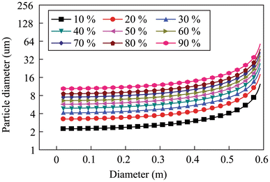
The related graph of d p and D2 (Q = 280)
Fig. 5 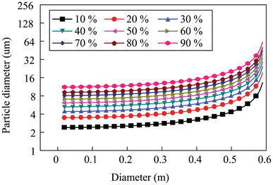
The related graph of d p and D2 (Q = 320)
Fig. 6 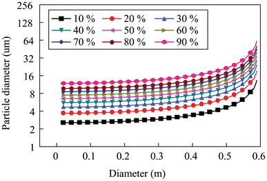
The related graph of d p and D2 (Q = 360)
Fig. 7 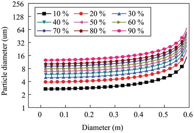
The related graph of d p and D2 (Q = 400)


Analyzed from Figs. 4, 5, 6 and 7, the results and discussions are illustrated as follows:
-
1.
Under the conditions of \(\eta_{{d_{p} }}\) = 10 % and D2 = 0.020 (D2 = 2R2), as Q increases from 280 up to 400, d p increases; and under the conditions of \(\eta_{{d_{p} }}\) = 90 % and D2 = 0.020, d p increases as Q increases; under the conditions of \(\eta_{{d_{p} }}\) = 10 % and D2 = 0.590, d p increases as Q increases; under the conditions of \(\eta_{{d_{p} }}\) = 90 % and D2 = 0.590, d p increases as Q increases. Synthesized the above four aspects, under the conditions of the fixed \(\eta_{{d_{p} }}\) and D2, the d p increases as the Q increases.
-
2.
Under the conditions of \(\eta_{{d_{p} }}\) = 10 % and Q = 280, as the D2 increases, the curve of d p and D2 becomes more and more precipitous; under the conditions of \(\eta_{{d_{p} }}\) = 90 % and Q = 280, as the D2 increases, the curve of d p and D2 becomes more and more precipitous; under the conditions of \(\eta_{{d_{p} }}\) from 10 % to 90 % and Q from 280 to 400, as the D2 increases, these curves of d p and D2 become more and more precipitous, as well as. Synthesized the above three aspects, as the Q and \(\eta_{{d_{p} }}\) increase, the curves of d p and D2 become more and more precipitous.
-
3.
Under the conditions of \(\eta_{{d_{p} }}\) = 50 % and Q = 280, as the D2 increases, the d p increases; under the conditions of Q from 280 up to 400, as the D2 increases, the d p increases. Under the conditions of \(\eta_{{d_{p} }}\) from 10 % to 90 %, as the D2 increases, the d p increases. Therefore, compared the same curvature of different curves, the D2 increases as Q/\(\eta_{{d_{p} }}\) increases.
-
4.
Under the conditions of D2 = 0.500 and Q = 280, as \(\eta_{{d_{p} }}\) increases, d p increases; under the conditions of D2 form 0.010 up to 0.590 and Q from 280 up to 400, as \(\eta_{{d_{p} }}\) increases, d p increases.
-
5.
As the flow rate of air current increases, dust removal efficiency decreases. The critical point, which is a sharply changing curvature point in the curve of between the coal dust particle diameter and the driven spiral blade radius, is nearer and nearer to the maximum of the horizontal axis in Figs. 4, 5, 6 and 7.
Additionally, the results of numerical calculations need to verify by test experiments, and the willing of engineering application of DCCP should be come realizable, step by step. At present, a general experiment system of dust removal devices for underground coal mines is built up, and is shown in Fig. 8. The next work will develop a prototype of DCCP, and experiment tests of the prototype will fulfill on the basis of the general experiment system of dust removal devices for underground coal mines.

The photo of a general experiment system of dust removal devices for underground coal mines
5 Conclusions
Through analysis of dust removal devices at home and abroad, the problems of a dust-removal fan were found out in the research and application in Chinese underground mines, furthermore, DCCP was designed.
-
1.
On the basis of Bradley’s balance orbit theory, the force analysis equations of CDRS in DCCP were deduced out. Based on the deduction, the general equation of dust removal efficiency is presented, and is shown as follows,
$$\eta_{{d_{p} }} \le 1 - {\text{e}}^{{ - \frac{{\pi^{3} }}{135} \cdot \frac{{\left( {\rho_{p} - \rho_{a} } \right)\left( {R_{1}^{2} - R_{2}^{2} } \right)}}{\mu } \cdot \frac{{L_{0} }}{Q}n^{2} d_{p}^{2} }}$$ -
2.
Based on the boundary conditions of an engineering case, the general equation was simplified step by step. The simplest equation is shown as follows,
$$\eta_{{d_{p} }} \le 1 - {\text{e}}^{{ - 6.0275 \times 10^{12} \cdot \frac{{\left( {0.3^{2} - R_{2}^{2} } \right)d_{p}^{2} }}{Q}}}$$ -
3.
Based on the results of numerical calculation of the simplest equation, focused on the volume flow rates of air current, dust removal efficiencies of CDRS, driven spiral blade radiuses and dust particle diameters, it is concluded as follows:
-
a.
The lower flow rate of air current is, the more beneficial to dust removal in CDRS is.
-
b.
The larger radius of driven spiral blade is, the more beneficial to dust removal in CDRS is.
-
c.
The larger particle diameter of coal dust is, the more beneficial to dust removal in CDRS is.
-
a.
-
4.
The next work of dust removal in CDRS should be focused on the optimization of the driven spiral blade radius and flow rate of air current, and be fulfilled experimental tests.
References
Belle B, Phillips HR (2009) Influence of section return dust levels as an exposure indicator and assessment parameter of engineering control in coal mines. J Mine Ventil Soc South Afr 62(4):6–9
Black N, Dilworth M, Summers N (2007) Occupational exposure to wood dust in the British woodworking industry in 1999/2000. Ann Occup Hyg 51(3):249–260
Bradley D, Pulling DJ (1959) Flow patterns in the hydraulic cyclone and their interpretation in terms of performance. Chem Eng Res Des 37(1):34–45
Clayton T, Crowe JD, Schwarzkopf MS, Yutaka T (2011) Multiphase flows with droplets and particles. Taylor & Francis Group, New York
Colinet JF, Goodman GVR, Listak JM (2005) Effective control of respirable dust in underground coal mines in the United States. Australasian Institute of Mining and Metallurgy, Victoria, pp 129–134
Faschingleitner J, Hoflinger W (2011) Evaluation of primary and secondary fugitive dust suppression methods using enclosed water spraying systems at bulk solids handling. Adv Powder Technol 22(2):236–244
Guo SJ (2007) Research on dust—removal mechanism and application of hydraulic dust collector. Min Safety Environ Prot 34(5):2–6
Hall E (2008) Coal miner responses to the personal dust monitor. Coal Age 113(4):42–44
Kissell FN (2003) Handbook for dust control in mining. National Institute for Occupational Safety and Health, Washington
Konorev MM, Nesterenko GF (2012) Present-day and promising ventilation and dust-and-gas suppression systems at open pit mines. J Min Sci 48(2):322–328
Koo J, Hong J, Lee H, Shin S (2010) Effects of the particle residence time and the spray droplet size on the particle removal efficiencies in a wet scrubber. Heat Mass Transf 46(6):649–656
Kulkarni P, Baron PA, Willeke K (2011) Aerosol measurement: principles, techniques, and applications. Wiley, Hoboken
Kuznetsov SI, Mikhailik VD, Rusanov SA (2012) Modeling of the hydrodynamics of a cyclonic rotational dust collector of increased efficiency. J Eng Phys Thermophys 85(2):349–355
Li YC, Lin AH, Liu RH (2007) Numerical simulation and experiment research on flow field of rotary air curtain. China Saf Sci J 17(06):18–24
Li JG, Gao BP, Wang YY, Wei HR, Zhao J (2012) Experimental research on pollutants precipitation of underground coal gasification. Meitan Xuebao 37(Suppl 1):173–177
Li QZ, Lin BQ, Zhao S, Dai HM (2013) Surface physical properties and its effects on the wetting behaviors of respirable coal mine dust. Powder Technol 233(1):137–145
Liu FZ (2011) Applications of wet dust blower by vibrating wire in coal heading surface. Shanxi Coal 30(03):96–97
Liu RH, Li XB, Shi SL (2009) Study on the influence of outlet angle of air curtain at full-mechanized work face on its dust-isolating effectiveness. China Saf Sci J 19(12):128–134
Liu RH, Wang PF, Zhang DC, Chen SQ (2012) Study on flow ratio of blowing to drawing of rotational jet shield ventilation at tunneling working face. China Saf Sci J 22(09):133–139
Masuda H, Higashitani K, Yoshida H (2010) Powder technology handbook. Taylor & Francis Group, New York
Naidoo RN, Robins TG, Seixas N (2005) Differential respirable dust related lung function effects between current and former South African coal miners. Int Arch Occup Environ Health 78(4):293–302
Onder M, Yigit E (2009) Assessment of respirable dust exposures in an opencast coal mine. Environ Monit Assess 152(1):393–401
Qin ZS, Liu R (2009) Effects of occupational coal dust exposure on lung function and haematology. China Occup Med 36(04):356–357
Reed WR, Organiscak JA, Page SJ (2004) New approach controls dust at the collector dump point. Eng Min J 205(7):29–31
Shorokhov VA, Smol’Nikov AP, Kurochkin DA, Komarova NN, Mar’Yasov AS, Gudovich AR, Bartosh SN (2009) Development of a mathematical model simulating the multiply connected automatic control system of a coal-fired power unit equipped with a direct-injection dust feed system. Thermal Eng 56(10):868–874 (English translation of Teploenergetika)
Torano J, Torno S, Menendez M, Gent M (2011) Auxiliary ventilation in mining roadways driven with roadheaders: validated CFD modelling of dust behaviour. Tunn Undergr Space Technol 26(1):201–210
Wei LX (2008) Practice and application of filtration wet cyclone dust precipitator. Coal 17(06):73–75
Zhang SS, Wang SJ, Li XY, Li SJ, Tang H, Li Y, Yu W (2013) Properties and harmfulness of lunar dust: a review. Diqiu Kexue 38(2):339–350
Zheng L (2011) Annual 57,000 miners suffering from pneumoconiosis in China. Saf Healthy 25(1):33–34
Acknowledgments
The research was supported by the National Natural Science Foundation of China and Shenhua Group Corporation Limited (U1361118); the Hunan Provincial Natural Science Foundation of China (13JJ8016); the State Key Laboratory for GeoMechanics and Deep Underground Engineering (SKLGDUEK1018); the Open Research Fund Program of Hunan Province Key Laboratory of Safe Mining Techniques of Coal Mines (Hunan University of Science and Technology) (201105); the Project of Outstanding (Postgraduate) Dissertation Growth Foundation of HNUST (SNY005).
Author information
Authors and Affiliations
Corresponding author
Rights and permissions
Open Access This article is distributed under the terms of the Creative Commons Attribution License which permits any use, distribution, and reproduction in any medium, provided the original author(s) and the source are credited.
About this article

Cite this article
Chen, S., Wang, H., Li, Y. et al. Theoretical and numerical analysis of coal dust separated by centrifugal force for working and heading faces. Int J Coal Sci Technol 1, 338–345 (2014). https://doi.org/10.1007/s40789-014-0039-9
Received:
Revised:
Accepted:
Published:
Issue Date:
DOI: https://doi.org/10.1007/s40789-014-0039-9