
Abstract
An enclosed cyclone passageway (ECP) dust-collecting fan is discussed. The ECP fan separates dust by centrifugal force originating from a driven spiral airflow, and its design takes the constraints of Chinese underground coal mines into consideration. Using the force equilibrium law, a general equation for dust removal in the centrifugal dust removal section (CDRS) of the ECP fan is deduced. This general equation is simplified using the CDRS structure and the fan operating parameters and is analysed numerically. The attractive results show that increases in the airflow rate of the fan, the structural ratio of the ECPs and the radius of the extended axis can improve the dust removal performance of the CDRS. Furthermore, the effects of the structural ratio and the radius on dust removal dominate over that of the flow rate, and the effect of the structural ratio is more significant than that of the radius.
1 Introduction
Overexposure to airborne respirable dust can cause disabling, even fatal, respiratory disease in mineworkers. Therefore, exposure to coal dust is always an important occupational health concern. According to official statistics for Chinese coal mines, over 2.65 million workers were exposed to coal dust, the pneumoconiosis detection rate was 7.2 % and the accumulated number of pneumoconiosis patients was over 57,000 (Zheng 2011). The occupational health risks mineworkers faced for being exposed to coal dust clouds are related to the metamorphic degree of the coal, the dust concentration and the cumulative exposure, among other factors (Naidoo et al. 2005; Belle and Phillips 2009; Onder and Yigit 2009; Qin and Liu 2009; Zhang et al. 2013). Statistical data from the US National Institute for Occupational Safety and Health (NIOSH) indicate that, with the increasing intensity of mining operations, the pneumoconiosis detection rate among workers exposed to coal dust in underground coal mines in the USA rose from 4 % in 1999 to 9 % in 2007 (Hall 2008). To reduce the pneumoconiosis detection rate among coal workers, or at least prevent it from increasing, the isolation and removal of dust at working/heading faces is the key measure, because the working face usually has the highest concentration of coal dust in a mine. Currently, the most effective method appears to be the isolation and removal of dust by ventilation or by collection with a dust catcher (Reed et al. 2004; Guo 2007; Li et al. 2007, 2012; Wei 2008; Liu et al. 2009, 2012; Liu 2011; Kuznetsov et al. 2012).
The dust catchers that are used in underground coal mines can be classified, on the basis of the dedusting mechanisms that they employ, as filtering, centrifugal separation and comprehensive systems (Colinet et al. 2005; Black et al. 2007; Shorokhov et al. 2009; Koo et al. 2010; Faschingleitner and Hoflinger 2011; Torano et al. 2011; Konorev and Nesterenko 2012; Li et al. 2013). In Germany, fibre bag precipitators are usually adopted in underground coal mines because of their high dust collection efficiency. However, they are very bulky. In Poland, cyclone dust collectors have a large share of the market. They bear advantages of a collection efficiency of up to 99.3 % and a dewatering efficiency of up to 98 %. Their disadvantages lie in an operating resistance of over 2,300 Pa and an even greater bulk than fibre bag precipitators.
The collection efficiency of the above-mentioned dust precipitators is usually higher than 95 %, but they are not suitable for Chinese underground mines. Because of limitations imposed by technology, economics and engineering geology, the excavation sections of Chinese underground mines are usually less than 15 m2 in area, and in most mines they are smaller than 10 m2, especially in Hunan, Jiangxi, Guizhou, Yunan, Sichuan and Chongqing. Therefore, the advanced dust precipitators used in Germany and Poland for example are too bulky or have a too high operating pressure drop for most Chinese underground coal mines. The performance of the dust collectors that are currently used in these Chinese mines is poor in a number of aspects: their efficiency of dust removal is low (about 80 %), their dewatering rate is low (less than 85 %) and the operating resistance is high (more than 2,200 Pa), and, even though they are smaller than the advanced precipitators used elsewhere, they are still too large (longer than 10 m or wider than 2.5 m) and in huge weight.
To improve mine air quality and dust collection performance, an enclosed cyclone passageway (ECP) dust-collecting fan has been designed and developed. This is a novel dust-collecting fan, which separates dust by the centrifugal force exerted by a driven spiral airflow. Its dust removal mechanism is thus different from those of existing dust collectors. In this study, a general equation for dust removal in the centrifugal dust removal section (CDRS) of ECP fan is deduced by applying the classic force equilibrium principle, which states that the centrifugal force on a dust particle should be equal to the aerodynamic resistance of the corresponding spiral airflow at a given spatial point. The equation is then simplified, and case studies are conducted for the ECP fan using the simplest form of the equation. Finally, the effects of structural and operating parameters on centrifugal dust removal in the CDRS are analysed through an engineering case study.
2 ECP fan and dust removal in CDRS
As illustrated in Fig. 1, the ECP fan consists of a fan (section B), a CDRS (the section between B and E) and a dewatering section (section E).

Sketch of ECP fan, 1 inlet bell, 2 fan, 3 spraying nozzle, 4 spiral blades of CDRS, the blades are fixed and cannot spin, 5 dewatering baffles, A polluted airflow, B fan section, D water sink, E dewatering section, F purified airflow, X, Y, Z, coordinate axes, H–H cross-section for Fig. 3
The polluted airflow (‘A’ in Fig. 1), carrying coal dust particles, is sucked into the ECP fan when the fan is running. Constrained by ECPs, the polluted airflow is transformed into a driven spiral airflow with axial, radial and tangential flow velocities (Mondal et al. 2004; Eldrainy et al. 2009). The dust particles are separated from the polluted airflow by the centrifugal force exerted by the tangential velocity of the driven spiral airflow, and the separated particles are captured by the water in the water sink. The wet airflow with the partly or fully separated dust cloud from the CDRS is dewatered by water baffles, and is then transformed into the purified airflow (‘F’ in Fig. 1).
3 Force analysis and centrifugal dust removal in CDRS
In the CDRS, the driven spiral airflow carries dust particles, which are acted upon by axial, radial and tangential force components.
The tangential force on a dust particle is not equal to the force from the polluted airflow. If the centrifugal force on the dust particle is larger than the force from the polluted airflow, then the dust particle may escape from the stream tube of the polluted airflow and will possibly move towards the inner wall of the CDRS, finally being captured by the water in the CDRS. This is the process by which single dust particles are separated by the driven spiral airflow and captured by the water. The process is cyclical as the polluted airflow flows through the CDRS, and the dust is removed continuously.
Figure 2 illustrates the structural parameters of the CDRS. They are related as follows:
where R1 is the radius of the CDRS cylinder (m), R0 is the radius of the extended axis (m), R is the radius at which a separated particle is located (m), L0 is the step length of the multiple ECPs along the Z axis (m), L1 is the total length of the multiple ECPs along the Z axis (m), L2 is the total length of a single enclosed driven cyclone passageway along the Z axis (m), N1 is the number of multiple ECPs and N2 is the number of L0 lengths within an angle of 2π radians in a single enclosed driven cyclone passageway.

Structural parameters of the CDRS in the ECP fan
Substitution of Eq. (2) into Eq. (3) gives
Referring to Fig. 2, it can be seen that
Both practical engineering experience and research have shown that Bradley’s balance orbit theory is suitable for the force analysis of floating large diameter dust particles (larger than 1 μm) and of falling dust (not smaller than 10 μm) (Bradley and Pulling 1959; Clayton et al. 2011). The theory is applied in this study to analyse the force and velocity on a coal dust particle in the CDRS. Figure 3, which is a cross-section of Fig. 2, illustrates the CDRS structural parameters and the force analysis for dust particles in the CDRS. A dust particle moving towards the inner wall of the CDRS is subjected to a viscous drag force exerted by a stream tube of the driven spiral airflow. On the other hand, the dust particle, transported by the driven spiral airflow, is also subjected to a centrifugal effect, namely a centrifugal force. Under approximately ideal conditions, ignoring other effects, the motion of the particle can be taken to be determined by these two forces. Under the action of the centrifugal force, with a radial velocity component, the particle moves continually towards the inner wall of the CDRS. At the same time, the drag force on the particle increases continuously, eventually becoming equal to the centrifugal force. When these forces are equal, the particle is in dynamic balance. The radius at which this condition holds is called the dynamic balance radius. In the CDRS, the centrifugal force and the drag force exerted by the airflow on the particle are given by Bradley and Pulling (1959) and Clayton et al. (2011),

Force analysis and structural parameters of the CDRS at cross-section H–H in Fig. 1, R1 radius of CDRS cylinder, R0 radius of extended axis, R x the minimum radius at which particle separation is possible, R radius at which separated particle is located, C centrifugal force; S drag force, ω p tangential velocity, v p radial velocity, a, b, c, representatives of particle cloud
respectively, where \(m_{p} = \pi d_{p}^{3} \left( {\rho_{p} - \rho_{a} } \right)/6\) is the relative mass of the particle (kg), u a is the linear velocity of the airflow in the spiral direction (m/s), R is the radius at which the moving particle is located in the spiral channel (m), ξ is the drag coefficient of the particle (dimensionless), \(F_{p} = 0.25\pi d_{p}^{2}\) is the projected area of the particle (m2), ρ p is the density of the dust particle (kg/m3), ρ a is the density of the airflow fluid (kg/m3), d p is the diameter of the particle (m) and ω p is the tangential velocity of the particle relative to the airflow (m/s).
For CDRS dust removal efficiency, the forces on dust particles should be in balance. This means that the drag force and centrifugal force on a particle should be equal (Kissell 2003; Masuda et al. 2010). From this condition, we can obtain the following Equation:
Furthermore, the square of the tangential velocity can be written as
Generally speaking, the smaller the dust particle, the more difficult it is for the particle to fall out of the flow. If a particle of 2.3 μm diameter can be separated by a centrifugal force, then a particle larger than 2.3 μm can also be separated. At a temperature of about 25 °C and a pressure of 1 atm (760 mmHg), if the relative velocity of a 2.3 μm particle is greater than 9.4 m/s, then the Reynolds number of the particle is greater than 2, and the relation between Reynolds number and the drag coefficient is in the transition region (Kulkarni et al. 2011).
For a flow rate of 160 m3/min and a channel radius of 0.300 m, the average velocity of the airflow is no less than 9.42 m/s (160/(60 × 0.3 × 0.3 × 3.14) = 9.426). At a flow rate of 360 m3/min, the Reynolds number of a 65 μm diameter particle is less than 1,000. The majority of the coal dust particles of interest in this study the Reynolds number is in the range from 2 to 800. Thus, the drag coefficient is given by the equation applicable to the transition region between the laminar and turbulent flow regimes (Lu 2008):
where μ the dynamic viscosity coefficient (Pa s).
Assuming that a dust particle can be represented by a rigid sphere and substituting Eq. (10) into Eq. (9), the tangential velocity of the particle can be calculated as
It is found experimentally (Sun et al. 2003; Liu et al. 2009) that the radial velocity of a spiral flow in a cyclone passageway is usually far lower than its overall speed in the spiral direction. Thus, the spiral linear velocity of the polluted airflow in the CDRS in Fig. 2 or Fig. 3 may be approximated as
where Q is the volume flow rate of a local fan in the ECP fan (m3/min). At a temperature of about 25 °C and a pressure of 1 atm (760 mmHg), the density of air is 1.18 kg/m3. The density of a dust particle is of the order of 103 kg/m3, and is thus much greater than that of air. Substituting Eq. (12) into Eq. (11), the tangential velocity ω p can be calculated as
At a given instant, the tangential velocity of a dust particle is defined as the ratio of the infinitesimal length travelled by the particle in an infinitesimal time and is expressed as
Substituting Eq. (13) into Eq. (14) gives
Mainly under the action of the centrifugal force, the dust particle moves from the minimum radius at which particle separation is possible to the inner wall of the CDRS. The time τ taken for the particle to travel this distance can be obtained by integrating the left hand side of Eq. (15) from t = 0 to t = τ and the right hand side from R x (the minimum radius at which particle separation is possible) to R1 (the radius of the CDRS cylinder):
Thus, τ is found to be
According to the basic theory of dust removal, the relaxation time for a dust particle can be calculated as (Kulkarni et al. 2011)
Comparing Eq. (17) with (18), it can be seen that the relaxation time for the dust particle is far smaller than its travel time to the wall of the CDRS. So the acceleration of the particle as it moves through the CDRS can be ignored. According to Eq. (5), in the spiral direction of the CDRS, the average travel time of a moving dust particle can be calculated as
where t0 is the average travel time of the airflow from CDRS inlet to CDRS outlet (s).
By substituting Eq. (12) into Eq. (19), the average travel time can also be expressed as
The dust removal mechanism in the CDRS relies mainly on dust separation by the centrifugal force and dust capture by the water surface, with the former playing the more important role. The necessary condition for a dust particle to reach the inner wall of the CDRS is that the time taken for the particle to travel to the inner wall in the radial direction should be no greater than the time taken for it to travel from the CDRS inlet to the outlet in the axial direction. That is,
Substituting Eqs. (17) and (20) into Eq. (21) gives
Then the minimum radius at which it is possible to separate particles can be expressed as
In the CDRS, the higher the airflow flow rate, the smaller this minimum radius, and vice versa. In other words, the greater the minimum radius for separating particles is, the lower the probability of particle separation by centrifugal force is. If the particle can be separated from the airflow at the minimum flow rate, which is the minimum volume flow rate of the ECP fan, then it must be possible to separate it by centrifugal force when the flow rate is higher than the minimum flow rate.
Assuming that the diameter of the dust particle is d p , if R (the radius at which the moving particle is located in the CDRS inlet) is larger than R x (the minimum radius at which particle separation is possible), the particle can reach (‘fall to’) the CDRS inner wall; otherwise, the particle will be carried by the airflow out of the CDRS. Thus, the minimum possible radius allowing separation of dust particles is a critical value, dividing the CDRS into a ‘fallen zone’ and a ‘non-fallen zone’. Under the condition R x ≤ R ≤ R1, the annular area is the fallen zone. Obviously, under the condition R0 ≤ R < R x , the annular area is the non-fallen zone; additionally, under the condition 0 ≤ R < R0, the radius at which the particle is located in is less than the minimum possible radius for particle separation and so the annular area is again the non-fallen zone. The differential volume elements (m3) of the fallen and non-fallen zones of the particle cloud in the CDRS are given by
respectively, where \({\text{d}}z\) is a differential length element (m) along the axial axis of the CDRS.
Assuming that the distribution of dust particles is homogeneous in the polluted airflow, the grade efficiency of a particle of diameter d p in the CDRS can be expressed using the statistical probability method (Kissell 2003; Masuda et al. 2010; Kulkarni et al. 2011). The hierarchical efficiency of a dust particle of diameter d p is
Substituting Eqs. (24) and (25) into Eq. (26) gives
and then, on substituting Eq. (23) into Eq. (27), it is found that
Assuming that the structural ratio of the CDRS is
where N is the structural ratio of CDRS (dimensionless). And substituting Eqs. (29) and (4), Eq. (28) becomes
Equation (30) is the general Eq. describing the effects of physical, structural and running parameters on the grade efficiency of a dust particle of diameter d p . Thus, the first objective of this study has been achieved.
Equation (30) involves nine variables (\(\eta_{{d_{p} }}\), R1, R0, N, ρ p , d p , L1, μ, and Q) and one constant. To improve the efficiency of dust removal, it is necessary to optimise these nine variables, and to do this, a simplification procedure will be applied to Eq. (30).
4 Simplification and case study
The nine variables in Eq. (30) are affected by each other, and can be analysed only by numerical computation. A numerical approach is also required to optimise the structural and operating parameters of the ECP fan so that it meets the engineering requirements for employment in Chinese underground mines. The steps of the numerical computation are as follows.
Step 1, it is assumed that the particles are of density ρ p = 1.4 × 10³ kg/m3 and that μ = 1.86 × 10⁻⁵ Pa·s at a temperature of about 25 °C and a pressure of 1 atm (760 mmHg). These values are substituted into Eq. (30). Then Eq. (30) is simplified.
Step 2, depending on the application conditions, the required quantity of airflow is calculated, and the capacity of fan dust collection is chosen. It is assumed that the required airflow rate is known and that FBD No 6.0 has been chosen as the local fan. The parameters of FBD No 6.0 are as follows: (1) the radius R1 of the cylinder inner wall is 0.300 m; (2) the volume flow rate ranges from 150 to 370 m3/min; (3) the total pressure ranges from 4,601 to 1,363 Pa; (4) the motor capacity is 2 × 15 kW; (5) the rotation speed is 2,900 rev/min.
Step 3, the radius R1 of the CDRS inner wall is determined according to the exit radius of the chosen fan. In the case study, the chosen fan is FBD No 6.0, with R1 = 0.300 m. This value is substituted into Eq. (30). Then Eq. (30) is simplified.
Step 4, taking account of the constraints imposed by engineering conditions in Chinese under-ground coal mines, it is assumed that L1 = 1 m. This value is substituted into Eq. (30). Then Eq. (30) is simplified.
Step 5, \(\eta_{{d_{p} }}\) may take any value from 0 to 100 %. When the grade efficiency is 50 %, this means that there is a 50 % possibility of a dust particle being separated by the CDRS, and the diameter of the dust particle is then called the cut-off aerodynamic diameter, or simply the cut diameter. According to the theory of dust removal, the smaller the cut diameter, the greater is the efficiency of CDRS dust removal, and so the cut diameters can be compared directly in the analysis of CDRS dust removal performance. Therefore, a grade efficiency of 50 % is assumed, and \(\eta_{{d_{p} }}\) = 0.5 is substituted into Eq. (30). Then Eq. (31) is simplified.
Equation (30) is simplified by Steps 1–5 and becomes
Step 6, from Eq. (4), when L1 = 1 m, N1·N2·L0 = 1 m. It is assumed in turn that L0 = 0.1, 0.2, 0.3, 0.4, 0.5, 0.6, 0.7, 0.8, 0.9 and 1.0 m. By definition, N1 must be a positive integer. Then, the value of N2 is calculated. For engineering applications, N2 must also be a positive integer. The calculated values of N2 are shown in Table 1.
From Table 1, when L0 = 1 m and N1 = 1, N2 = 1, so N = 1.000 from Eq. (29). For L0 = 0.5 m, when N1 = 1, N2 = 2, so N = 16.00, and when N1 = 2, N2 = 1, so N = 0.500. For L0 = 0.2 m, whenN1 = 1, N2 = 5, so N = 625.0, and when N1 = 5, N2 = 1, so N = 0.200. For L0 = 0.1 m, when N1 = 2, N2 = 5, so N = 312.5, when N1 = 5, N2 = 2, so N = 3.200, when N1 = 10, N2 = 1, so N = 0.100. Therefore, N = 0.100, 0.200, 0.500, 1.000, 3.200, 16.00, 312.5 or 625.0. These values are substituted into Eq. (31) in turn. Then Eq. (31) is simplified.
Step 7, when the fan has been chosen, the range of the volume flow rate is determined; that is, Q can be evaluated. Assuming Q = 280, 320, 360 or 400 m3/min when the chosen fan is FBD No 6.0, these values are substituted into Eq. (31) in turn. Then Eq. (31) is simplified.
Step 8, it is noted that it is impossible for the radius of the extended axis to be larger than the radius of the CDRS inner wall, that is, R0 ≤ R1. If R0 = R1, there are no more spiral blades in the CDRS, which is not a realistic situation. Nor is the case R0 = 0, which indicates that there is no extended axis in the CDRS. Therefore, Eq. (31) can be further simplified by taking R0 in the range 0 < R0 < R1. When R1 = 0.300 m, assuming that 0.05 < R0 < 0.20 and that the step value of R0 is 0.001, the value of d p can be calculated using the simplified Eq. (31).
Equation (30) is simplified by Steps 1–5, and the case studies are conducted for the ECP fan using the simplest Eq. (31) in Steps 6–8. Thus, the second purpose of this study is fulfilled.
5 Results and discussions
When Q and N are assumed constant, there are only two variables in Eq. (31), namely d p and R0. The numerical calculation of Eq. (31) is implemented using the MATLAB package.
The results of the numerical calculations for the relationships between d p and R0 for different values of Q are shown in Figs. 45, 6, 7, 8 and 9, from which the following can be seen:

Relationship between d p and R0 for Q = 160 m3/min

Relationship between d p and R0 for Q = 200 m3/min

Relationship between d p and R0 for Q = 240 m3/min

Relationship between d p and R0 for Q = 280 m3/min

Relationship between d p and R0 for Q = 320 m3/min

Relationship between d p and R0 for Q = 360 m3/min
-
(1)
Fig. 4 shows that when Q = 160 m3/min, d p increases with decreasing N and decreases with increasing R0.
-
(2)
Figs. 5, 6, 7, 8 and 9 show that higher values of N and R0 are beneficial to dust removal in the CDRS.
-
(3)
The results of the numerical calculations for the relationships between d p and Q for different values of R0 are shown in Figs. 10, 11, 12 and 13, from which the following can be seen:
Fig. 10 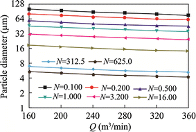
Relationship between d p and Q for R0 = 0.05 m
Fig. 11 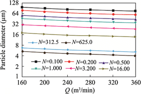
Relationship between d p and Q for R0 = 0.10 m
Fig. 12 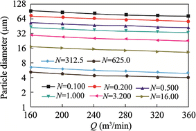
Relationship between d p and Q for R0 = 0.15 m
Fig. 13 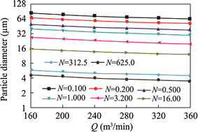
Relationship between d p and Q for R0 = 0.20 m
-
(4)
Fig. 10 shows that when R0 = 0.05 m and Q = 160 m3/min, d p decreases very significantly from 102.9 μm to 5.6 μm as N increases from 0.100 to 625.0. Additionally, when Q = 360 m3/min and R0 = 0.05 m, as shown in Fig. 4, d p decreases very significantly from 78.5 μm to 4.3 μm as N increases from 0.100 to 625.0.
-
(5)
Figs. 11, 12 and 13 show that larger values of Q are beneficial to dust removal in the CDRS.
-
(6)
Comparing Figs. 4 and 13, it can be seen that the effect of N is more significant than the effect of R0 and that the effect of R0 is more significant than the effect of Q.
-
(7)
A combined optimisation of N and R0 may be possible, with the combination being related directly to a critical value of R0. Therefore, one direction for future work would be to investigate this critical value.


6 Conclusions
-
(1)
A general equation expressing the grade efficiency in terms of the particle diameter has been derived.
-
(2)
With constraints imposed by the boundary conditions of an engineering application, the general equation has been simplified step by step, and the simplest equation, which expresses the effects of structural and running parameters on the grade efficiency, has been applied in a case study.
-
(3)
It is found that the efficiency of dust removal in CDRS should improve with increasing airflow rate, radius of extended axis and structural ratio. The effects of the radius and structural ratio on the efficiency are far more significant than that of the flow rate.
-
(4)
The effect of the structural ratio on the efficiency dominates over that of the radius, but an increased radius can further improve dust removal under the condition of a fixed structural ratio. Furthermore, this beneficial effect of the increased radius becomes more and more noticeable as the radius approaches that of the CDRS cylinder.
-
(5)
The next work of dust removal in CDRS should be focused on the optimization of de-dusting efficiency and energy loss, and be building up a prototype of FECP, and be fulfilling its experiment tests.
References
Belle B, Phillips HR (2009) Influence of section return dust levels as an exposure indicator and assessment parameter of engineering control in coal mines. Journal of the Mine Ventilation Society of South Africa 62(4):6–9
Black N, Dilworth M, Summers N (2007) Occupational exposure to wood dust in the British woodworking industry in 1999/2000. Ann Occup Hyg 51(3):249–260
Bradley D, Pulling DJ (1959) Flow patterns in the hydraulic cyclone and their interpretation in terms of performance. Chem Eng Res Des 37(1):34–45
Clayton T, Crowe JD, Schwarzkopf MS, Yutaka T (2011) Multiphase flows with droplets and particles. Taylor & Francis Group, New York
Colinet JF, Goodman GVR, Listak JM (2005) Effective control of respirable dust in underground coal mines in the United States. Australasian Institute of Mining and Metallurgy, Victoria, Austrlia, pp 129–134
Eldrainy YA, Saqr KM, Aly HS et al (2009) CFD insight of the flow dynamics in a novel swirler for gas turbine combustors. Int Commun Heat Mass Transfer 36(9):936–941
Faschingleitner J, Hoflinger W (2011) Evaluation of primary and secondary fugitive dust suppression methods using enclosed water spraying systems at bulk solids handling. Adv Powder Technol 22(2):236–244
Guo SJ (2007) Research on dust—removal mechanism and application of hydraulic dust collector. Min Saf Environ Protect 34(5):2–6
Hall E (2008) Coal miner responses to the personal dust monitor. Coal Age 113(4):42–44
Kissell FN (2003) Handbook for dust control in mining. National Institute for Occupational Safety and Health, Washington
Konorev MM, Nesterenko GF (2012) Present-day and promising ventilation and dust-and-gas suppression systems at open pit mines. J Min Sci 48(2):322–328
Koo J, Hong J, Lee H, Shin S (2010) Effects of the particle residence time and the spray droplet size on the particle removal efficiencies in a wet scrubber. Heat Mass Transfer/Waerme- und Stoffuebertragung 46(6):649–656
Kulkarni P, Baron PA, Willeke K (2011) Aerosol measurement: principles, techniques, and applications. Wiley, Hoboken
Kuznetsov SI, Mikhailik VD, Rusanov SA (2012) Modeling of the hydrodynamics of a cyclonic rotational dust collector of increased efficiency. J Eng Phys Thermophys 85(2):349–355
Li YC, Lin AH, Liu RH (2007) Numerical simulation and experiment research on flow field of rotary air curtain. China Saf Sci J 17(06):18–24
Li JG, Gao BP, Wang YY, Wei HR, Zhao J (2012) Experimental reserach on pollutants precipitation of underground coal gasification. Meitan Xuebao/J Chin Coal Soc 37(SUPPL. 1):173–177
Li QZ, Lin BQ, Zhao S, Dai HM (2013) Surface physical properties and its effects on the wetting behaviors of respirable coal mine dust. Powder Technol 233(1):137–145
Liu FZ (2011) Applications of wet dust blower by vibrating wire in coal heading surface. Shanxi Coal 30(03):96–97
Liu RH, Li XB, Shi SL (2009) Study on the influence of outlet angle of air curtain at full-mechanized work face on its dust-isolating effectiveness. China Saf Sci J 19(12):128–134
Liu RH, Wang PF, Zhang DC, Chen SQ (2012) Study on flow ratio of blowing to drawing of rotational jet shield ventilation at tunneling working face. China Saf Sci J 22(09):133–139
Lu HG (2008) Introduction to power technology. Tongji University Press, Shanghai
Masuda H, Higashitani K, Yoshida H (2010) Powder technology handbook. Taylor & Francis Group, New York
Mondal S, Datta A, Sarkar A (2004) Influence of side wall expansion angle and swirl generator on flow pattern in a model combustor calculated with k–ε model [J]. Int J Therm Sci 43(9):901–914
Naidoo RN, Robins TG, Seixas N (2005) Differential respirable dust related lung function effects between current and former South African coal miners. Int Arch Occup Environ Health 78(4):293–302
Onder M, Yigit E (2009) Assessment of respirable dust exposures in an opencast coal mine. Environ Monit Assess 152(1):393–401
Qin ZS, Liu R (2009) Effects of occupational coal dust exposure on lung function and haematology. China Occup Med 36(04):356–357
Reed WR, Organiscak JA, Page SJ (2004) New approach controls dust at the collector dump point. Eng Min J 205(7):29–31
Shorokhov VA, Smol’Nikov AP, Kurochkin DA, Komarova NN, Mar’Yasov AS, Gudovich AR, Bartosh SN (2009) Development of a mathematical model simulating the multiply connected automatic control system of a coal-fired power unit equipped with a direct-injection dust feed system. Therm Eng (English translation of Teploenergetika) 56(10):868–874
Sun J, Niu ZM, Zhang JX (2003) Experimental study on velocity distribution of horizontal vortex and inner energy dissipating tunnel with inlet shaft. J Hydrodyn 18(02):240–247
Torano J, Torno S, Menendez M, Gent M (2011) Auxiliary ventilation in mining roadways driven with roadheaders: validated CFD modelling of dust behaviour. Tunn Undergr Space Technol 26(1):201–210
Wei LX (2008) Practice and application of filtration wet cyclone dust precipitator. Coal 17(06):73–75
Zhang SS, Wang SJ, Li XY, Li SJ, Tang H, Li Y, Yu W (2013) Properties and harmfulness of lunar dust: a review. Diqiu Kexue—Zhongguo Dizhi Daxue Xuebao/Earth Science—J China Univ Geosci 38(2):339–350
Zheng L (2011) Annual 57,000 miners suffering from pneumoconiosis in China. Saf Healthy 25(01):34
Acknowledgments
This work described in this paper was supported by the Natural Science Foundation of China and Shenhua Group Corporation Limited (U1361118), the Hunan Provincial Natural Science Foundation of China (13JJ8016, 2015JJ2061), the State Key Laboratory for Geomechanics and Deep Underground Engineering (SKLGDUEK1018), the Project of Scientific Research Fund of Hunan Provincial Education Department (Nos. 12C1099, 14C0425).
Author information
Authors and Affiliations
Corresponding author
Rights and permissions
Open Access This article is distributed under the terms of the Creative Commons Attribution License which permits any use, distribution, and reproduction in any medium, provided the original author(s) and the source are credited.
About this article

Cite this article
Chen, S., Chen, Y., Wang, H. et al. Effects of structural and operating parameters of ECP fan on dust particles removed in the transition flow regime. Int J Coal Sci Technol 1, 441–449 (2014). https://doi.org/10.1007/s40789-014-0046-x
Received:
Revised:
Accepted:
Published:
Issue Date:
DOI: https://doi.org/10.1007/s40789-014-0046-x