
Abstract
The paper focuses on new opportunities of knowledge sharing, and comparison, thanks to the circulation and re-use of heritage HBIM models by means of Object Libraries within a Common Data Environment (CDE) and remotely-accessible Geospatial Virtual Hubs (GVH). HBIM requires a transparent controlled quality process in the model generation and its management to avoid misuses of such models once available in the cloud, freeing themselves from object libraries oriented to new buildings. The model concept in the BIM construction process is intended to be progressively enriched with details defined by the Level of Geometry (LOG) while crossing the different phases of development (LOD), from the pre-design to the scheduled maintenance during the long life cycle of buildings and management (LLCM). In this context, the digitization process—from the data acquisition until the informative models (scan-to-HBIM method)—requires adapting the definition of LOGs to the different phases characterizing the heritage preservation and management, reversing the new construction logic based on simple-to-complex informative models. Accordingly, a deeper understanding of the geometry and state of the art (as-found) should take into account the complexity and uniqueness of the elements composing the architectural heritage since the starting phases of the analysis, adopting coherent object modeling that can be simplified for different purposes as in the construction site and management over time. For those reasons, the study intends (i) to apply the well-known concept of scale to the object model generation, defining different Grades of Accuracy (GOA) related to the scales (ii) to start fixing sustainable roles to guarantee a free choice by the operators in the generation of object models, and (iii) to validate the model generative process with a transparent communication of indicators to describe the richness in terms of precision and accuracy of the geometric content here declined for masonry walls and vaults, and (iv) to identifies requirements for reliable Object Libraries.
Introduction
In recent years, the growing use of informative model requires new form of dissemination using different type of devices and cutting-edge technologies. In particular, sharing informative model in the form of object libraries within the Common Data Environment represents a great opportunity. On the other hand, object libraries oriented to the Architectural Heritage represent a challenge because they should cope with object complexity and uniqueness.
The “Introduction” section takes into account a particular family of objects, the vaults, that are widely spread out in the world from many centuries, commonly classified within elementary categories, not correspondent to the diverse construction techniques that the instruments and sensors nowadays available allow detecting, favoring proper geometric modeling. The “Sharing the knowledge on Construction History managing heritage multiplicity: why library of objects—the case of vaulted systems” section briefly discusses the literature about vaulted system. The paper starts with the problem statement illustrating the necessity of sharing the knowledge on the Construction History in order to manage such multiplicity allowing vaults comparisons across space and time through the proposed innovative informative libraries coming from accurate HBIM models; the section “The star vaults and the Italian-Czech family of artists, architects, and master builders: the Santini-Aichl” describes the case study of the St. Bernard’s chapel at the Plasy Monastery (Czech Republic) that highlights the specificity of star vaults and the Santini-Aichel Italian-Czech family of artists, architects, and master builders, and thus the high interest of creating shared object libraries.
The chapel is one piece of the Construction History stories in the eighteenth century, which involves the Italian-Czech Santini family of artists and architects with a multiplicity of connections across Europe. These connections are expressed at two different levels: from one side architects and craftsmen that traveled to work from Northern Italy to Northern Europe; on the other, the dissemination of the same vault typologies in the whole Europe.
The “HBIM object libraries: a critical analysis of gaps, risks, missed points, to-do list, and potentials” section reports a critical analysis and potentials of BIM object library highlighting the specificities connected to the generation of an HBIM object library in the case of architectural heritage with respect to the new buildings, and BIM specifications, thus the need of new requirements.
The “Grades of Accuracy and Grades of Generation for scan-to-BIM model process: specification proposal inheriting the representation scale concept” section in the context of the conceptual and methodological approach of the Heritage Building Information Modeling (HBIM) intends to start fixing some roles to guarantee the choice of the proper precision, accuracy, and richness of the models by the creators in the function of the different constraints and purposes, guaranteeing at the same time a transparent communication of such choices, measurable and comprehensive.
It concerns the specification proposals in terms of accuracy related to the model scale definition. The choice of the representation scale is based on the proper Grade of Accuracy (GOA) and on the different Grades of Generation (GOG), which make it possible to manage a scan-to-HBIM process of heritage buildings, avoiding misinterpretations of 3D survey data and supporting users in the selection of the proper scale (“HBIM models, scales, and grades of 3D model accuracy: specifications, scales of representation, and tolerance” section). The scales of 3D object accuracy are declined for two common components, a case of masonry wall (“Cases of wall object: scale models and model generation specification” section), and a case of complex vaulted system, such as the St. Bernard’s chapel vault (“HBIM of St. Bernard’s chapel star vault in the Plasy Monastery: model generation with different scales” section). The two case studies allow authors to test the capability of the specifications to support the choice of high precision models, as well as intermediate and low level of simplification, in the function of the characteristics of the object and of the different modeling purposes, highlighting the lack of content information when adopting lower GOAs for complex object and the richness of knowledge generated in the case of higher GOAs. The “General roles derived for elaborate domes like the star vaulted system: deviation from the conceptual solids (as a semi-sphere, or portions, or conic solid, polycentric solid and curves, elliptical solid, or any other complex solids or generative curves such as ovoidal polycentric shapes)” section derives general roles to guide the generative process of domes, such as star vaulted systems, by adopting different GOAs.
The experiences carried out by many groups in the heritage information modeling are demonstrating that improving the Level of Geometry and information allows increasing the results in terms of knowledge, discovering techniques, and geometries that were adopted in the construction process to solve aesthetical and structural issues (Condoleo 2018; Stanga et al. 2019; Tucci et al. 2019). Several studies underlined how the level of geometric detail and accuracy and the understanding of the constructive logic of the object can improve its knowledge as well as its digital representation, exponentially increasing the amount of information connected to each single HBIM object (Banfi 2020; Chow et al. 2019).
Thus, the adoption of complexity as a meter of model generation should circulate among the actors, who re-use such models, through tangible indicators of the reached accuracy. Furthermore, the adoption of simplified models needs to be declared in order to avoid faulty inferences on the objects when comparing libraries of different objects modeled with different GOAs. Given that object models are generated by different professionals for different purposes (with different technologies, precision, and details), this paper intends to raise situational awareness among the operators in the re-use of such models to avoid mismatching in the data sharing.
Many HBIM models, although deriving from accurate surveying methodologies and instruments, can be interpreted as synthesis models (Suwardhi et al. 2015), because they answer to the specific commitment of HBIM generation and arenot specifically addressed to the understanding ofconstruction techniques, as the stereotomic capacity of workers to manage the spatial construction with complex shapes and solutions. On the other side, many of them are addressed to the management phase and less oriented to the investigation of the object itself (Eadie et al. 2013; Azhar et al. 2012; Volk et al. 2014).
In the context of the Heritage Building Information Modeling (HBIM), the 3D informative models are the objects in which data are stored and made accessible to the different specialists. Once defined the scales and generative roles, in the “A proposal for HBIM Levels of Geometry (100–500) as a function of the phases, the Levels of Development” section, a novel concept for HBIM Levels of Geometry (LOGs 100–500) is proposed to support the HBIM preservation process as a function of the HBIM phases (the Levels of Developments), overcoming the simple to complex LOG logic of the building construction. Thus, it considers the specificity of the Levels of Development when dealing with the architectural heritage, along with all the different phases characterizing the preservation process, from the digital documentation to the design (conservation plans) until the construction site and the Life Cycle Management (“Specifications on HBIM object library components: Level of Geometry (100–500) within the different Levels of Development—LODs and LOGs in the new construction protocols (AEC and NBS) and HBIM addressing in the heritage domain” section). The “Levels of Geometry (100–200–300–400–500–600) proposal in the heritage domain” section introduces HBIM targeted Levels of Geometry that are here related to the heritage objects and to the object library generation. In some cases, the Level of Geometries do not include specific subjects required by HBIM in the Building Construction. Therefore, it has been proposed to add such specific items, as in the case of the historical reports and data collection (LOG100), crucial and mandatory in the HBIM starting phase, or in the case of the on-site digital documentation and surveying (LOG200), passing through the HBIM geometric modeling phase compliant with the GOA adoption (LOG300)—as exploited in the “Grades of Accuracy and Grades of Generation for scan-to-BIM model process: specification proposal inheriting the representation scale concept” section; in other cases, the BIM design development phase is turned into the HBIM specificity introducing the HBIM uses (conservation plan—LOG400) that start from the analytical phases (i.e., material and decay mapping, diagnostics) to be addressed to the decision-making and at the end enriched by mean of the BIM uses implementing the design process (i.e., BIM-to-FEA, BEM, and WBS).
The “Research developments for LOG600: Geospatial Virtual Hub with linked HBIM implementation to manage object libraries and a BIM-based collaborative cloud platform” section presents research developments for LOG600, so far not enough implemented in the daily BIM, and HBIM, management. It represents the common space where one can remotely access HBIM sources and manage the Long Life Cycle Management and continuous monitoring. It can be used as well for communication to the experts and non-expert users and to the public, circulating the information coming from the object libraries that were generated and validated.
A Geospatial Virtual Hub application with Linked HBIM object libraries (i) and a BIM-based collaborative cloud platform have been developed (ii): a geographic open source virtual hub has been implemented to increase the re-use and comparison of the HBIM models and HBIM object libraries accessible within a common geospatial environment linked to HBIM object library (“Common Data Environment: beyond scan-to-BIM models to increase collaborative communication” section); finally, the multiplicity of the gathered data is readily available for cross-queries. The Geospatial Hub allows the comparison across space and time of the linked HBIM object libraries. A Common Data Environment (CDE), open-BIM-cloud platform, managing the HBIM object libraries with some applications is illustrated (“Live monitoring, data remotely accessed, and application connected to BIM” section).
Sharing the knowledge on Construction History managing heritage multiplicity: why library of objects—the case of vaulted systems
Vaulted systems have been increasingly studied by scholars. In Italy, the primary studies until a few years ago were the extensive collections on construction techniques offered by Manuali and Atlanti that provide construction details of historical buildings for those approaching preservation works. Being an operational tool, Manuali and Atlanti simplify the building elements, without showing all the variables of one building feature. However, in recent years, the vaulted systems analysis is becoming a systematic field of research, particularly in the context of Mediterranean stereotomy studies, such as the ones in Calabria, Sicily, and Sardinia (Nobile 2013; Garofalo 2016). On the other hand, some studies focus on specific vault features, i.e., the lunettes or the frame vault (Grimoldi 2009) or particular type of vaulting (Grimoldi 2018).
French and Spanish studies offer a different approach, where the analysis on stereotomic vaults has become a particular field of study in the Construction History (Becchi et al. 2018). These studies are encouraged by precise construction figures (trompes, arrière-voussure, voûte, etc.), whose design (trait) is included in the treatises on stereotomy from the sixteenth century, first of all, those of De l’Orme (1567) and Derand (1643), and whose realization is expressed in a series of clearly recognizable variants. For this reason, the books by Pérouse de Montclos (2013) and Palacios Gonzalo (1990), just to quote the best known, respectively in France and Spain, become entirely part of the literature on Construction History. Other works can be mentioned, such as Huerta’s studies on the relationship between design, geometry, and construction of vaulted systems (Huerta 2004).
Gothic Architecture’s rediscovery in the late nineteenth century in Germany and England has been a way to study the construction techniques of vaulted systems made of stone or brick. While studies on the fan vaults (Leedy 1980) of Gothic cathedrals disseminated throughout the UK have been of great interest in England, the netzgewölbe of churches and palaces in Germany have been widely analyzed by Wendland, which uses reverse engineering to rediscover their construction techniques (Wendland 2014). Few studies highlight how architectural treateses are related to the objects and their geometry. One of these is the research by Wendland on the analysis of the shape and appareillage (bricks arrangement) of the nineteenth-century vaults by architect Lassaulx (Wendland 2008), author of an interesting essay about building vaults without scaffolding. This study is relevant to understand how the construction logic of brick block vault follows that of stereotomy, i.e., that the same vault typology may have different appareillage.
Studies on the vault geometric genesis (Vitali et al. 2019) have also shown that the relationship between the type of vault and the vault geometric genesis is not alwaysunivocal. Different solids of rotation can generate the same vault shape as well as different construction techniques can be used for its realization. Furthermore, geometric discrepancies between the original and the real vault shape may be due to the vault construction process or the building settling over time.
However, it is still missing a comprehensive approach that joins together the historical and geometric data on the construction of vaulted systems. Nowadays, thanks to advanced surveying techniques, it is possible to reach a high level of accuracy in the geometric survey of buildings and architectural elements. In the case of vaulted systems, this helps to get a reliable analysis of vault profile and curvatures. Geometric analysis, together with non-invasive inspection (such as IRT), shed lights on vault construction techniques. Thus, the acquired information on one individual case is the most diverse: geometric-dimensional data (drawings, such as plans and cross-sections, information coming from a non-invasive survey), description of the building (report or historical documents), photographs, name of the architect or craftsmen, building contracts, etc. The paper intends to boost the potentials of object library generation capable to model such concepts and to manage such variety contributing to enhancing research and knowledge. Even in the case of architectural elements, such as the vaulted system, HBIM is becoming the proper tool to keep and share data among professionals. Furthermore, if HBIMs are included in virtual hubs within a geospatial context and used in a Common Data Environment, they can be a vehicle of information sharing to the experts and to a greater audience, with the possibility to making queries through “reading key” and comparing different dataset across time and space.
Star vaults and the Italian-Czech family of artists, architects, and master builders: the Santini-Aichel
Star vaults are generally defined as “vaults whose rib patterns suggest a star” (Getty Vocabulary, Art & Architecture Thesaurus), thus including a great variety of vaults, which can belong to different typologies. Figure 1 shows some of those different star-rib patterns. On the other hand, the star pattern can depend on the vault design, such as St. Bernard’s chapel lunettes radial configuration.

Variation on the theme of star vaults (Cavallari-Murat 1963)
Star vaults have been used more and more since the fourteenth century and are often geometrically and constructively described in stereotomic architectural treatises that were disseminated in most European libraries, such as L’Architecture des voutes by Derand (1643). An example of star vault is the voute moderne pour une eglise described in Le premiere tome de l’architecture (1567), by Philibert de l’Orme.
It is possible that also the architect of St. Bernard’s chapel, Jan Blažej Santini-Aichel, was inspired by such treatises. Although looking toward the renaissance architecture, this treatise still included the practical knowledge of the gothic buildings. Jan Blažej Santini-Aichel (1677–1723) was the third generation of Italian builders in Prague, and he is most known for his unique baroque-gothic style. During his training, Santini visited Italy and was influenced by the architecture of Borromini and Guarini. Thus, Santini’s architecture is a synthesis of the local gothic master builders tradition and the high baroque culture as already mentioned (Kalina 2010). Santini belonged to a family of Italian architects and builders who settled in Prague around the seventeenth century. Santini’s grandfather, Antonio, migrated from Lugano to Prague; Santini’s father, Santyn Aychl, worked in important building sites, such as the extension of the Prague Castle. The migration of architects and artists to Northern Europe is a specific feature of Northern Italy builders trained in Italy. Most of them came back home after the working season; others settled in foreign cities. This paper moves toward a shared HBIM object library map because it starting to fix rules in the generation of the model object that could support many authors developing their models. The gathered information on star vaults has been implemented within the object library generation as illustrated in the following sections: “Grades of Accuracy and Grades of Generation for scan-to-BIM model process: specification proposal inheriting the representation scale concept,” “A proposal for HBIM Levels of Geometry (100–500) as a function of the phases, the Levels of Development,” and “Research developments for LOG600: Geospatial Virtual Hub with linked HBIM implementation to manage object libraries and a BIM-based collaborative cloud platform.”
Figure 2 shows the tangible characteristics of the research case study. As already briefly anticipated in the previous paragraph, the paradigms of uniqueness and geometric complexity of this constructive element is a characteristic that must be handed down adequately. The choice of this case, in addition to being selected for its geometric characteristics, was also dictated by the need to share a large amount of historical, architectural, cultural, and geographical information.

St. Bernard’s chapel. Left: Vault intrados: eight lunettes and ribs, central frescos by artist J. A. Pink. Top right: vault extrados: Y-shaped ribs with interlocking bricks on the two edge of the lunettes. Bottom right: lunettes brick arrangement
St. Bernard’s chapel (Fig. 2) is one of the four corner-room of the huge Cistercian monastery founded in Plasy (Czech Republic) in the twelfth century. It was renovated in the first half of the eighteenth century by architects Jean Baptist Mathey and his pupil Jan Blažej Santini-Aichel. The chapel was realized between 1707 and 1710 and was finished while Santini was still alive. Artist Jakub Antonín Pink (1690–1748) painted the central vault fresco in 1724.
A first photogrammetric and geometrical survey was carried out in November 2018 to acquire a first dataset that allows the generation of the intrados and extrados orthophotos, the HBIM model, and the first drawings (Stanga et al. 2019). The vault intrados is characterized by eight lunettes, arranged in a radial pattern that support a dome-shaped surface with a fresco in the middle. The lunettes belong to the same dome-shaped surface, as visible in the cross-section of the chapel. The ribs between the lunettes, which span from the central fresco and reach the vault springing, resemble a star. The chapel has a circular plan, diameter 11 m, the vault has a clear span of about 5.5 m, and a rise of 5.5 m, spring-line at 8.50 m from the ground. Therefore, Santini probably based the design of the vault on a sphere (dome).
The extrados is characterized by Y-shaped ribs that start from the center, continuing straight and dividing in two following the lunettes groins. They are built so that the bricks adapt to the central dome-shaped surface, characterized by bricks arranged in circular rows, and to the lunettes, characterized by soldier laid bricks.
Star vaults characterized other structures built by Santini, such as St. John Nepomuk at Zelená Hora and the chapel of the Epiphany of Our Lord in Smiřice. The first one, built around 1719–1722, is a cupola interpreted by five lunettes, a similar layout to St. Bernards’ chapel, although in St. John Nepomuk, the ribs between the lunettes are much larger than in Plasy. The second one, built around 1706, is a cupola interpreted by eight lunettes, much more similar to the Plasy vault, and whose star pattern is emphasized by its decoration. Those buildings should be the next one to be analyzed to understand if Santini and his builders used the same construction techniques as in Plasy.
For all these reasons of a historical and cultural nature, one of the main objectives of this study is to demonstrate how the representation of a complex parametric object requires the definition of new guidelines capable of supporting the generative aspect and the information sharing not traceable in a standard BIM library. The added value of the scan-to-HBIM process, the scales of representation, guiding the accuracy (GOAs) within the generative process GOGs, the LOG data management, the creation of an object library capable of representing even the intangible values of a complex structural element, and the creation of digital hubs are decisive for increasing the communicative values of the model and sharing it in an appropriate way among the various users involved in the life cycle of such unique architectural elements.
HBIM object libraries: a critical analysis of gaps, risks, missed points, to-do list, and potentials
Construction Industry is continuously updating and delivering the object libraries shared among the professionals, supporting the decision-making process in their daily work. It should also be considered that the exponential growth of BIM object libraries worldwide is increasing steadily (AIA 2015; NBS 2020). Manufacturers, customers, and creators of BIM models use these libraries to communicate an ever-increasing amount of information and geometric characteristics. On the other hand, as seen in recent studies and application cases, the world of HBIM objects collides with the standardization of default libraries of the leading BIM platforms. For this reason, world-class research has highlighted the need to go beyond traditional BIM representation techniques, favoring the growth of scan-to-HBIM projects where the “value of the measurement” and the typological and morphological uniqueness are respected at different Levels of Geometry, of details and representation scale.
The definition of object libraries as “collection of a huge range of specific manufacturer objects” for different uses in an “informative collaborative and efficient way” represents a common point among construction industry libraries and historical catalogs in the form of HBIM Libraries. In parallel, some points heavily need to be differentiated respect to the heritage HBIM catalog from the BIM object library as hereafter described. If “the key part of the ecosystem represented by the plug-ins, allowing to drag and drop BIM objects directly into the NBS specifications” is valid in one direction (from BIM generation to the object library publication in the HBIM), it is not applicable in the other direction, from Object LIbraries to HBIM, copying and pasting the created objects within similar cases: we strongly need to generate the specific object starting from its surveying, “hic et nunc” and then to use the other object libraries for comparison, not to flattering the richness of the vault solutions. In the case of the architectural heritage, we have to avoid copying and pasting “similar models,” which risks eliminating each component’s uniqueness, applying the parametric logic in an unfeasible way: the access to the object libraries must allow us comparing the available objects within an increasing vast state of the art of the construction techniques, to better comprehend permanences and mutations of similar objects, highlighting their specificity, for example under the geometric, morphologic and constructive points of view, creating a comprehensive collection of objects not matching, in-fact, the traditional typological classifications too simplified compared to the multiplicity of vault shapes.
Another point to be clarified is related to the concept of details of an object library. In the case of new building construction, BIM follows the construction process, and the richness of the detail (LOGs) is clearly defined following the different steps and construction phases (LODs). However, in the case of the architectural heritage, it often happens that the 3D volumetric representation and the adoption of the Level of Geometry of one single object are sometimes derived from the professional skills and capacity of the modelers more than from the geometric characteristic of the object itself. The level of detail explicated by the Level of Geometry is mostly unconscious, sometimes qualitatively defined without feasible rules, sometimes unacceptable for the complexity of historical objects, such as the cases of vaulted systems, or is adopted with no reference to the required scale and the specificity of the object to be modeled. When generating the HBIM models, it becomes mandatory to start defining and adopting proper model accuracy, namely the concept of Grade of Accuracy (GOA) and Level of Geometry (LOG) as explained in sections “Grades of Accuracy and Grades of Generation for scan-to-BIM model process: specification proposal inheriting the representation scale concept” and “A proposal for HBIM Levels of Geometry (100–500) as a function of the phases, the Levels of Development.”
In the context of vault construction, some published HBIM case studies are demonstrating an unsuspected variety of construction techniques introduced by skilled workers across Europe: as it is the case of corner “trompe” mixed to a central dome but appearing as a cloister vault (Attico et al. 2019), or, again, corner “trompe” applied to cloister vault in order to obtain a continuous surface, sometimes adopting light thickness vaults with tiles covering large halls.
All these object libraries can generate many opportunities: clear guidelines and specifications can help growing building capacity of BIM/HBIM modelers, BIM creation, and re-use among restorers, responsible of monitoring and planned maintenance program, throughout multiple case studies that can be considered as testbeds under different points of view: these libraries can contribute to a better-informed process of the construction techniques adopted in the past, cross-relating the models, properties, and information gained by the single researches, such as the study on the family of workers across Europe (Della Torre et al. 1998) or the Santini’s family, throughout data processing obtained following modeling protocols, feeding Common Data Environment to share such libraries that can be also used for e-learning program among citizens within virtual museums.
Many other aspects have to be taken into account to pave the way for object standards delivery in the Heritage Domain, starting from the interoperability issue. Considering the barriers created from non-BIM-enabled Objects (as meshes, TIN, massive topographic component, and DTM), a generative methodologyhas already been investigated to assure interoperability among modeler’s tools and parametric tools, supporting the capacity building among professionals and students of architecture and engineering courses.
Different levels of analysis will be transferred through these object libraries that can be considered as punctual nodes addressed to guarantee a feasible and correct use of data that will circulate faster. Suppose HBIM is a vehicle of data attraction and data sharing; in that case, each HBIM can be considered a node of information that is progressively enriched by differentiated levels of data depending on the types of analysis, the availability of research funding, the intervention of preventive maintenance or restoration, and other issues. This requires facing the problem of data validation from a different point of view.
If one adopts an HBIM object to analyze ancient construction techniques or morphology for structural purposes or monitoring an object across the years, he needs to know which precision or simplification has been used and which he should need, avoiding mismatches in the implementation and use of the BIM object itself.
For this reason, the paper proposes a differentiated HBIM oriented Levels of Development—respect to the BIM logic—mainly referred to the scan-to-BIM Level of Geometry and Grade of Accuracy.
Grades of Accuracy and Grades of Generation for scan-to-BIM model process: specification proposal inheriting the representation scale concept
In this paragraph, the authors introduce the concept of scale in the model generation, demonstrating the importance of adopting new scan-to-BIM requirements and reference scales for the generation of 3D model as unique elements of their kind. The growing need to escape from a preconceived logic of BIM object libraries for new buildings has led to the definition of a method based on the following research objectives.
It was found that in the scan-to-BIM process, GOGs and GOA, and LOGs, are fundamental concepts introduced in the digitization process of the built heritage to improve multiple aspects such as:
-
i.
the specifications required to define a generative process based on point clouds coming from surveying (terrestrial laser scanning or mobile techniques, photogrammetry),
-
ii.
the level of the information linked to each parametric object (new customized HBIM parameters, schedules, and BIM databases, including the scale of model generation),
-
iii.
a reliable HBIM models capable of orienting itself to different types of BIM-based analysis and uses (HBIM model export through open source and proprietary formats).
In this context, the definition of new scan-to-BIM modeling requirements, such as GOAs, is decisive for the generation of complex architectural elements in order to address the model generation following the GOG specifications. It overcomes the pre-set logic of BIM default libraries and simple objects (as generally followed for the creation of new buildings) that do not communicate the peculiarities (geometric and semantic) of such unique elements, in favor of ad hoc specification process.
For those reasons, in the next paragraph, an HBIM model specification is proposed starting from the commonly recognized concept of representation scales defining different level of details and tolerances indicators: the concepts of graphic error, tolerance and grades of generation, and accuracy, have been related to the final purpose of declaring the reliability of the scan-to-HBIM model at different scales of representation and tolerance.
How to evaluate a 3D model? It is the model committed at the scale 1:100 feasible for my purposes? What does it mean that a model has a 1:100 scale? If I have a model generated with the precision of a 1:100 scale, is it useful to understand the morphologic shape and the construction techniques, or the state of its conservation? To answer these questions, we have to start from a commonly shared specification that can be fixed for the different scales to different 3D models. Then, in the function of the thousands of variables of the constrain and decision context, every actor can associate a proper scale to generate a proper model. This way actors and users can decide if the model, coming from previous analysis, requires further integration or if the model needs to be simplified at a certain point of the data management (i.e., for energetic purposes using standard tools not enabled to manage complex model).
HBIM models, scales, and grades of 3D model accuracy: specifications, scales of representation, and tolerance
To reliably share a model, such as a vault BIM object, one needs to know the following: which was the commitment purpose and thus the required scale; how it has been surveyed; if the model has been generated in a congruent way that depends on the object level of complexity and the type of geometrical survey in order to generate an object model with the proper accuracy. This information should be included within the Level of Information of each object model in order to manage the different Level of Geometry within the different phases as described in the “A proposal for HBIM Levels of Geometry (100–500) as a function of the phases, the Levels of Development” section.
Some constraints, roles, and specifications need to be fixed to guarantee the needed accuracy in the model’s generation. The proposal is to inherit the surveying specification concept traditionally linked to the different map representation scales (as for the case of the scale 1:25.000 for territorial maps, i.e., IGM maps, Istituto Geografico Militare, the Geographic Military Institute in Italy, or the scale 1:10.000 and 1:5000 for the technical regional-scale maps, 1:2000, 1:1000 and 1:500 for the municipality technical maps, etc.), as standardized in the aero-photogrammetric process adopted in the cartographic world, and inherited by the architectural surveying specifications (1:100, 1:50, 1:20, 1:10, 1:1), now addressing them to the 3D HBIM model objects. Such requirements have been adopted for many decades in the tenders’ specifications at a worldwide level. In these cases, the simple basic role conventionally adopted is the minimum level of detail (the so-called Graphic Error, G.E.) and the related Tolerance (T). The choice of the “scale” depends on the survey’s objective and the type of use of the final product (Banfi 2019; Brumana et al. 2019): once defined, clear indicators allow to generate and to validate the output.
Given the conventional definition of Graphic Error fixing the smallest detail that can be represented at a given scale (G.E. = 0.2 mm,) and tolerance (T = 2 ÷ 3 G.E. value), we can apply such values to all the different scales obtaining an indicator of precision and domain usability. If we relate the minimum graphic details (pixel or vector) to the real object (the correspondent physical object, as in the case of the Terrain Pixel value), we derive the following proportion: “1: n = G.E.: x,” where “n” is the scale factor (20, 50, etc.) and “x” is the correspondent dimension of the G.E. on the ground or on the architectural object that can be a façade or a plan or section.
For example, at 1:50 scale, the G.E. value is 1 cm, and the admitted tolerance (T) is 2 ÷ 3 cm, while for the 1:20 scale, G.E. is 4 mm, and T is equivalent to a ranging value (8 ÷ 12 mm). The Grade of Accuracy is automatically associated with the chosen scale. Technical municipalities’ maps at the scale 1:1000 have G.E. = 200 mm and T = 400 ÷ 600 mm, as illustrated in the first 4 columns of Table 1. In the case of photogrammetric restitution (as rectified images or orthoimages), the minimum detail is fixed at half the G.E. value at the given scale, with a restrictive requirement in order to consider the whole data processing (third column).
The precision of the surveying instruments and restitution scale needs to be coherent with those values to make them reliable by the technical uses and users. For this matter, the specifications for tender of maps production as well as for large-scale architectural surveys are strictly related to the concept of scale or scales adopted (i.e., global surveying at 1:50 scale with some details at 1:20, others at 1:10, depending on the different purposes and specificity of the object). Every architect knows that a drawing of a window for its manufacturing or preservation requires 1:5 ÷ 1:10 scales to properly represent some specific details. The photogrammetric mosaic floor of the Basilica of San Marcus has been realized at a 1:1 scale to represent the “waving” floor for the maintenance purposes and intervention on the single “tessera” (Monti et al. 2006).Table 1 illustrates the concept of scales related to the HBIM 3D models object created by the generative process to respect the richness of detail and tolerance fixed in the given scale. A model generated at the common scale 1:50 implies a minimum detail equivalent to 10 mm and a tolerance contained among 20 ÷ 30 mm.
The scale index of an object model is here proposed to be explicated by the Grade of Accuracy (GOA10, GOA20, GOA50, GOA100) defines automatically the different minimum detail to be taken in account and tolerances admitted in the modeling generations (Table 1, columns 6 and 7). Thus, GOA 20 means that the model accuracy of vaults as well as other components (as the octagonal columns in the Basilica di Collemaggio) with respect to the cloud points needs to be contained within the tolerance at that scale (T 20 = 8 ÷ 12 mm). The precision of the surveying, as in the case of point clouds acquired with TLS (laser scanner FARO Focus 3D), allows the extraction of vertical and horizontal profiles with high accuracy (2 ÷ 5 mm), thus coherent to the scales GOA20 and GOA50. Obviously in case we choose model scale bigger than the surveying precision (as it happens when we require 1:20/1/10 scale for porfiles and out of plumbs analysis), it will work in favor of the object model that will be generated, not the opposite!
The selection of the proper scale of the object model is complementary to the orthoimage scale definition. It can also happen to define a lower model scale (i.e., GOA50 for the HBIM model) and a higher orthoimage scale (i.e., 1:20) for the model texturing, obviously, we will have different tolerances. And in the common praxis, it often happens: given the short distances of indoor contexts among the principal point of the digital camera and the object to be acquired, i.e., the vault intrados, the terrain pixel coming from the photogrammetric image block (conventionally set at G.E./2 for the different scales) ranges from 1 ÷ 2 mm dependently from the distances from the camera parameters and the object surface; thus, the richness of the data acquired is coherent to scales that range from 1:20 to 1:10, without any additional effort (time and cost) in the surveying phase. The specification related to the adoption of the smallest detail of the pixel unit correspondent to half the G.E., inherited from the cartographic domain, takes into account the average of the “scale” of the photogrammetric images, with the different distances from the objects, the distortions, and the whole image data processing. Thus, the data entry quality concerning the whole process guarantees the output scale in terms of quality.
Once fixed the HBIM model scale with its indicators (G.E. and T), the second step to be clarified in the specification is how to guarantee a model generation coherent with the chosen scale as defined in the following paragraphs.
NURBS-based modeling and descriptive geometry are defined in the Grades of Generation (GOGs) 9 and 10, where the 3D architectural representation from point clouds meets the measurement value. Behind these concepts emerges the growing need to faithfully represent the detected artifact, thus ensuring its reliability for subsequent uses (Banfi 2020).
The following paragraphs describe the case of a Wall Object and Vaulted Object to guide the end-users across selecting the proper scale in the function of geometry, modeling and general objectives.
Cases of wall objects: scale models and model generation specifications
Different scales can be thus adopted in the same HBIM design project following the lesson learnt from the Basilica di Collemaggio in L’Aquila (Brumana et al. 2018a) adopting a global 1:50 GOA scale for the wall objects, and a GOA scale 1:20 for the most damaged South Wall with the Holy door without of plumb ranging from 10 ÷ 20 cm after the earthquake.
In the case of the Basilica di Sant’Ambrogio in Milan (Banfi et al. 2019), the particular curved waved wall (round 46 cm with respect to a virtual plane) adjacent to the left nave at the women gallery level has been modeled generating the wall object characterized by a double curvature at the scale 1:20 in order to analyze that specificity to carry on the hypothesis on the wall generation, transformation, and supposed reinforcing (Fig. 3). Given the complexity of the wall and the maximum range of the undulation, its simplification and degeneration to a single parallelopiped correspond to urban scales (GOA2000, T800 ÷ 1200 mm, clashing the arches, or GOA1000, T400 ÷ 600 mm keeping the arches in the model) and not to a 1:100 scale generally considered a simplified scale! In fact, a GOA100 would mean to take into account the deformation with respect to a virtual plan within 40 ÷ 60 mm. Obviously, it is a case limit but it is worth stressing the point.

Three possible models (GOA2000, 1000, 20) of the same wall. GOA can change according to project requirements, scales of representation, and tolerance. The Automatic Validation System (AVS), obtained at the end of the NURBS-based modeling, allows to understand the standard deviation of the surfaces from the cloud points (in case of a laser scanning survey)
GOAs 50 and 20 roles are hereafter described for the model generation.
Case of GOA50-wall object
Planarity check: standard deviation ≤ 20 ÷ 30 mm
Case of walls (or portions) with a standard deviation of the point clouds surveyed representing the physical object respect to the average plane surface in correspondence of the façade surfaces (internal and/or external) ≤ 20 ÷ 30 mm: the planarity check can be easily carried out using the available functionalities within modelers’ tools and/or BIM tools. In this case, a 1:50 scale (equivalent GOA50) is chosen: the objects can be modeled adopting simplified Grade of Generations 1–8 (Brumana et al. 2019).
Research of Plane Extraction Methods can be inherited to guide toward the proper scale selection with the support of automatic and semiautomatic point interpolations (Wang et al. 2016).
GOGs 1–8 define simplified functionalities (i.e., based on extrusion, subtraction, sweep, and other modeling functionalities). Where needed, it is possible to associate the different options to model sub-portions (as in the case of openings, or irregular plan profile with discontinuities coming from the transformation occurred across the centuries or others): the discretization of the overall object is made by subdividing its homogeneous elements, checking the planarity and modeling the different portions. Void and subtraction functions can be used to model the complexity of a historical stratified wall.
GOG 1–8: simplified solid model objects can be adopted for elements whose conceptual model (in this case planarity check) has standard deviation respect to the cloud points ≤ 20 ÷ 30 mm (i.e., vertical walls with non-planarity or out of plumbs ≤ 20 ÷ 30 mm).
Planarity check: standard deviation ≥ 20 ÷ 30 mm
Case of walls (or portions) with a standard deviation of the point clouds respect to the average plane surface in correspondence of the façade surfaces (internal and/or external) ≥ 20 ÷ 30 mm: if the planarity check gives back this range of values, it means that the wall within this scale cannot be considered a plan at the given 1:50 scale - thus the out of plumbs need to be checked for the structural analysis (as in the case of Collemaggio’s Basilica walls), or characterized by voluntary morphological shapes adopted in the construction phase, to be further decoded, as in this case.
GOG 9–10: NURBS-based model object built on the primitives (profiles) or on the cloud points together with the 3D border outline can be thus adopted for elements with standard deviation respect to the adopted conceptual simplified solid ≥ 20 ÷ 30 mm (i.e., vertical walls with standard deviation respect to the planarity check ≥ 20 ÷ 30 mm, or without of plumbs ≥ 20 ÷ 30 mm; or pillars with standard deviation respect to the planarity check ≥ 20 ÷ 30 mm).
If this scale is not enough to understand the state of the art, it can be shifted toward a deeper scale 1:20 (equivalent GOA20): the objects are modeled adopting the GOGs 9–10 (NURBS-based object modeling), embodying the complexity of the shape to follow the geometry discretized by the point clouds.
Case of GOA20-wall object
Planarity check: standard deviation ≤ 8 ÷ 12 mm
GOG 1–8: simplified solid model objects can be adopted for elements whose conceptual model (in this case planarity check respect to the intrados and extrados a plane surface) has standard deviation respect to the cloud points ≤ 8 ÷ 12 mm.
Planarity check: standard deviation ≥ 8 ÷ 12 mm
GOG 9–10: NURBS-based model object can be adopted for elements whose conceptual model (in this case planarity check respect to the intrados and extrados plane surface or planes with different orientation as in the case of scarf walls) has standard deviation respect to the conceptual simplified solid ≥ 8 ÷ 12 mm.
HBIM of St. Bernard’s chapel star vault in the Plasy Monastery: model generation with different scales
A different GOA (200–100–50–20) adoption is illustrated for a complex vaulted system. Vaults generally have a more complex geometry than the typology classification based on simplified volumes and their intersection: detailed surveying of intrados and extrados, together with thermal images analysis, allows one to detect shapes that are different from the conceptual solids coming from the technical literature (Brumana et al. 2018b).
This paragraph describes the different scales and accuracy applied to different GOAs (GOA20, GOA50, and GOA10) to detect the geometry and the construction techniques, depending on the available information. In this case, intrados and extrados of St. Bernard’s chapel star vault were studied through on-site observations, geometric surveys, and photogrammetry.
At the intrados, the star vault can be schematically represented by a sphere interpreted by 8 lunettes that creates arches, while at the extrados, it is framed by radial Y-ribs.
A proper scale was defined for each component of the star vault, taking into account (i) the survey precision gained (and also surveying limitations due to the context and museum management), (ii) the geometric characteristics that could be evidenced adopting the proper scale, and the particularity of the surface finishing (i.e., the intrados stuccoes and the raw mortar finishing of the extrados). Each object model scale characterized by different tolerance factors has driven the model generation of the vault components.
In order to filter the stuccoes decoration at the intrados and to analyze the geometry of the framed ribs and of the lunettes, it has been chosen a 1:20 scale adopting a GOA20 in the modeling phase. The intrados surface has been surveyed and modeled at a 1:20 scale, generating an HBIM object at GOA20. Since the vault construction technique is an example of so-called frame vault (arches and lunettes), the HBIM model generation has been addressed to the segmentation of these two object elements.
Modeling the whole star vault object does not only require a reliable intrados model, adopting GOA20 to detect the geometry of the ribs and lunettes, but also an integration of the extrados textured model with GOA50. The extrados, due to surveying constraints and mortar cover irregularities given back from the photogrammetric orthoimage and point clouds, was modeled at a 1:50 scale, with a range tolerance of 20 ÷ 30 mm. However, from the extrados, it was possible to see the arrangement of the bricks, thus understanding the construction technique and the connection with the intrados. Thus, a detail of the Y-ribs was modeled at GOA10 to represent the arrangement of the bricks on the vault and lunette extrados surface (Fig. 4). The analysis made it possible to derive a more in-depth knowledge of the construction technique to better support the vault structural behavior and boost the preservation actions.

Intrados (vault and lunette) geometric analysis: (A) the longitudinal section of the vault is a segmental arch that has a deviation from a round arch of about 18 cm (worst case); (B) lunette profile is a segmental arch that deviates from the round one of about 18 cm (worst case); (C) lunette transversal section is a part of a round arch whose center is not at the same level of the end of the arch; (D) lunette transversal section is a segmental arch that deviates from the round arch of about 10 cm; (E) lunette profile is a curve that deviates from the line of about 6 cm
Model generations and specifications
HBIM model generation followed the specification steps for the generative model of complex shapes (Banfi 2019). It was then adapted to the different GOAs:
-
Extraction of primitives from point clouds to intercept the primary geometry: this process can be done manually or in a semi-automatic way. It should be stressed that the geometric interpretation of the collected data and the constructive analysis of the product depend totally on the modeler.
-
From the NURBS model to HBIM objects: thanks to NURBS algorithms, it was possible to apply GOG 10 where it was necessary. Through a semi-automatic procedure, simple points were turned into a model capable of accurately following the vault geometry, both at the intrados and the extrados. The upper and lower vault parts have been connected and georeferenced directly in a three-dimensional environment thanks to common points identified in the wall texture. In the generative phase, GOG 10 scan-to-BIM requirements, the scale of representation, and the amount of information included in the model had been considered. An accurate breakdown by structural elements consequently determined the level of information shared via BIM parameters, clouds, and databases. NURBS-based models have been generated with the intrinsic characteristic of being HBIM enabled parametric complex object.
-
The Grade of Accuracy and the scale of representation definition, validation, and communication of the object library (toward HBIM metadata enrichment): the definition of methods capable of validating and communicating the model reliability to the various users has been undertaken. Communicating the specific GOAs and the scale of representation adopted for each model component within the HBIM information properties, through known quantitative parameters, is vital for each phase of BIM uses after the HBIM model generation within the HBIM contest but also in the case of data sharing outside the single HBIM use. For this reason, the HBIM object, before being shared, must be verified connecting such values as a sort of metadata: an Automatic Verification System (AVS) has been applied to different scales of representation with the ultimate goal of demonstrating the level of accuracy, analyzing the quality level (Banfi 2019).
-
Implementation and development of new HBIM parameters enriching the object library: as briefly mentioned, the need to create a library of unique objects, such as St. Bernard’s chapel, required the development of new description parameters for communicating a series of contents, such as construction, materials, arrangements, family of workers, and geolocation with more specific information such as historical periods, descriptions, and historical documentation from the archives. External links could also redirect the collected data, such as orthophotos, texts, point clouds, 2D drawings, and historical reports.
GOA20—the intrados and the lunettes
The intrados and the lunettes structure of the star vault were modeled with GOA20 (a Grade of Accuracy of the model equivalent to 1:20 scale).
GOA20 means that the object model accuracy respect to the cloud points will be contained within the tolerance at that scale (T20 = 8 ÷ 12 mm). This factor implies that to model the object with such precision, it is required reliable modeling of the intrados. This object cannot be modeled at this scale with a sphere!
Such accuracy highlighted the complex typology and detected the creativity of the geometric design (Stanga et al. 2019). Thanks to the direct application of GOG 9 and 10, it has been possible to go beyond a simple 2D representation or simplified theoretical representation.
The analysis on the shape and dimension of vault sections and lunettes profiles was carried out (Fig. 4). The longitudinal section of the vault (A) is not a round arch but is a segmental arch. It slightly deviates from the round arch of about 18 cm (worst case). Considering the lunettes: B profile is a segmental arch that deviates from the round one of about 18 cm (worst case), C transversal section is a part of a round arch whose center is not at the same level of the end of the arch, D transversal section is a segmental arches that deviates from the round arch of about 10 cm, and E profile is a curve that deviates from the line of about 6 cm.
Santini would probably get inspiration from the pure solids for the design of the vault (a sphere), since he was keen onmathematics and geometry. Then, why those discrepancies between the conceptual model and the real vault? Many reasons could explain those deviations: problems during the construction process (a bad construction of the centering or problems during de-centering), the thickness of stuccos and paintings, settlement of the building across the centuries (the Monastery was built in the twelfth century on a water-land on 5100 oak piles to reinforced the swampy ground) or a voluntary adoption of curves characterized by multiple centers (polycentric arches).
Moreover, since the E profile of the lunettes is not a straight line, it means that the lunette surfaces are not built by the translation of the segmental arch. They are surfaces with double-curvature, which means that they were probably built without using a centering, or maybe using the groins of the lunette as a centering. This hypothesis could be possible, but the brick arrangement of the lunettes is longitudinal and it does not match the herringbone pattern, which is the usual pattern for free-hand vault (Wendland 2008). In the case the lunettes were built using a centering, it could be possible that they place some sand on it to give curvature to the E profile, perhaps due to aesthetic reason. To properly model such complex geometries, the modeling process of the lunettes and ribs at the intrados is illustrated adopting GOA20 with the result of modeling the curvature of the intrados not approximating a simple semi-circumference—as from the profile analysis—but the geometric curvature by extracting the primitives and the borders, thus obtaining the wireframe model as explained in Fig. 5.

GOA50, GOA 20, and GOA10 models of the research case study
GOA50—the skeleton of the framed star vault
The extrados was modeled following the rules mentioned above (GOA50): components with standard deviation respect to the generative conceptual solids ≤ 20 ÷ 30 mm can be modeled with a Grade of Accuracy of 1:50 scale (GOA50). The extrados gives some hints on the vault construction technique: the sphere is stiffened by 8 Y-shaped ribs that move from the center toward the middle of the lunettes to divide along their sides (Fig. 5). The sphere and the lunettes are interlocked with the ribs thanks to the arrangement of the bricks.
GOA10—the sample of the arrangement textured model of the brick block units at the extrados
Figure 5 has a focus on the model GOA50 of the extrados, showing the arrangement of bricks in three-dimensions. The bricks on the vault are arranged along concentric lines and on the lunettes are laid following their axes. The two directions meet in the ribs, where the bricks make a 90° angle. On the ribs, some bricks are arranged header to create a connection with the intrados. This scale increased the richness of the shape coming from the 3D textured model, helping to derive a more in-depth morphologic analysis and comprehension of the construction logic, the knowledge on the construction technique, and the structural behavior, which are preconditions for a hypothetical preservation work. However, some constructive issues remain pending, and further IRT analysis should be made at the intrados with active IRT methodology (obtained heating the hall, Grimoldi et al. 2013), which could highlight the brick arrangement at the intrados and the relationship between intrados ribs and lunette connections or between intrados ribs and extrados ribs, as hereafter explained.
Thermal images allow detecting the arrangement of vault bricks even if the intrados is covered by plaster. In the case of Magio Palace in Cremona, thanks to the IRT, it has been possible to understand the construction techniques of the cloister vault. The cloister vault was not realized traditionally, as one could expect, but it was a in foglio vault reinforced by extrados ribs, transversal and longitudinal to the walls, whose bricks are intertwined with the ones of the vault (Brumana et al. 2018c). The HBIM of the vault was modeled at the scale 1:20.
In conclusion, the use of “primary shapes” (double curved or flat surface, semicone, etc.) can be useful to compare the elements and to understand the constructive genesis of a component (wall, lunette, rib, or others). The “primary shapes” can be used in the representation of objects (GOG1–8) when the standard deviation with respect to the point clouds is within the tolerance of the chosen scale; vice versa when the standard deviation is not verified (it is outside the tolerance of the chosen scale), then a NURBS-based object must be generated to better approximate the point clouds (adopting the Grade of Generation 9 or 10), or we have to adopt a smaller and less accurate scale if we donot want to model the object with that accuracy.
General roles derived for elaborate domes like the star vaulted system: deviation from the conceptual solids (as a semi-sphere, or portions, or conic solid, polycentric solid and curves, elliptical solid, or any other complex solids or generative curves such as ovoidal polycentric shapes)
As illustrated in the previous example, a general role can be derived and adopted for the modeling generation. The standard deviation check is carried out on the object components (represented by the point clouds) with respect to the generative conceptual solids.
GOA50 standard deviation from the conceptual solid model ≤ 20 ÷ 30 mm
Following the above rules, components with standard deviation respect to the generative conceptual solids ≤ 20 ÷ 30 mm can be modeled with a GOA adopted for 1:50 scale (GOA50). For example, when modeling a dome supposed to be semispheric, the conceptual solid will be a half sphere and will be used to model the object if the standard deviation is maintained within the given range of that scale ≤ 20 ÷ 30 mm.
GOG 1–8: simplified solid model object (in this case, a half sphere) can be adopted for elements whose solid conceptual model has a standard deviation of≤ 20 ÷ 30 mm.
If not verified, the solid must be changed at this scale or the scale must be changed (i.e., checking an ovoidal shape or free forms with double curvatures).
GOA50 standard deviation from the conceptual solid model ≥ 20 ÷ 30 mm
GOG 9–10: for elements whose conceptual model (in this case a half sphere) respect to the intrados or extrados surface, represented by the cloud points, has a standard deviation ≥ 20 ÷ 30 mm respect to the cloud points, the sphere cannot be adopted to model the object. Thus, a NURBS-based model object can be generated using the borders and the primitives (GOG9) or the borders and the cloud points (GOG10). In elaborate vaults or domes, the standard deviation check is made on the generative conceptual solid that can also imply simple curvature solid (cylinder, cone), or double curvature surfaces/solids, or paraboloids (Bertolini Cestari 2011), or other geometrical surfaces to be analyzed at that scale.
GOA20 standard deviation from the conceptual solid model ≤ 8 ÷ 12 mm
Elements with standard deviation respect to the generative conceptual solids ≤ 8 ÷ 12 mm can be modeled with a GOA adopted for 1:20 scale (GOA20). For example, the “trompe,” which should have a generative conic conceptual solid, can be modeled with a conic solid portion just if the standard deviation is kept within the given tolerance at the scale 1:20.
GOG 1–8: simplified solid model object (a cone in the “trompe” case) can be adopted for elements whose conceptual solid model has a standard deviation of respect to the cloud points ≤ 8 ÷ 12.
GOA20 standard deviation from the conceptual solid model ≥ 8 ÷ 12 mm
GOG 9–10: for elements whose conceptual model (such as the lunettes of St. Bernard’s vault) respect to the intrados or extrados surface, represented by the cloud points, has a standard deviation ≥ 8 ÷ 12 mm, the cone cannot be adopted at that scale (GOA20) as highlighted by the generative profile geometry. Thus, NURBS-based model object can be adopted using the double curvature generative of the lunettes. To clarify the concept with another example, the NURBS process has been adopted to analyze the particular geometry in case of a vault composed by a central dome and trompe at the corners, for which the traditional simplification represented by cones was not reliable to describe its construction technique (Attico et al. 2019). As mentioned before, in elaborate vaults or domes, the standard deviation check is made on the generative conceptual solid that can also imply double curvature surfaces/solids, paraboloids, etc.
A proposal for HBIM Levels of Geometry (100–500) as a function of the phases and the Levels of Development
The definition of the GOA concept and of the different model scales needs to be related to the whole HBIM process and adopted within the different phases of a restoration and conservation process, supporting the object library generation. HBIM Level of Geometry to be intended as a function of the phases of development (LODs) is here after proposed and adapted to the HBIMs, passing through the analytic and design phases led by different actors and operators, till the construction site management, maintenance and communication phases. Phases mandatory in the knowledge process to get a preservation plan are totally missed in the Level of Geometry described for the BIM construction, therefore they have been here proposed.
The different GOAs (ranging from complex model to its simplification) can be chosen within the so-called Level of Development (LOD) phases and Level of Geometry (LOGs), depending on the HBIM users and actors orientation phases as hereafter summarized. The terms Level of Development and Level of Geometry are commented facing the specificity of the architectural heritage object with a proposal of adapting their content respect to the new construction specifications.
Specifications on HBIM Object Library components: Level of Geometry (LOGs 100–500) within the different Levels of Development. LODs and LOGs in the new construction protocols (AEC and NBS) and in the HBIM addressing the heritage domain
The term LOD in the BIM context has different interpretations in literature. The AEC (CAN) BIM Protocol (2014) and AIA (2015) describe the Level of Development referred to the different phases of construction: from the Conceptual Design to the Design Development, Construction Stage, and Facility Management. Consequently, the LOG (Level of Geometry) and LOI (Level of Information) describe each LOD, specifying the different details, progressively required at the given phase of the construction process. Other interpretations are addressing LOD to the Level of Detail, that in our opinion, is less clear since it can overlap with the LOG (Level of Geometry) and LOI (Level of Information). The term LOD in the NBS 2015 Level of Development is related to the different construction phases (LOD100–500), i.e., LOD 100 refers to the pre-design phase and LOD500 gives all the useful information about the building management across time (Long Life Cycle Management) after closing the construction site and starting from the as-built updating. This phase includes the maintenance process and programs, and it is to be located in the 6D Facility Management “Dimension.” The progression of LODs and LOGs in the case of a BIM Object, i.e., a window or door, is explained in Fig. 6. The LOG concept in the case of new construction is progressively enriched by details gaining the maximum of richness in the Facility Management phase of Development through the LOG500 aimed to manage and document the “as-built” model objects after the construction process.

LOGs (Level of Geometry 100–500) within the different LODs (Level of Development 100–500 phases) of the BIM building construction: the cases of doors and windows
Within this sequence, a BIM object for new construction (as in the case of a tower) should embody the maximum geometric details and information in the facility management phase (LOD500). An object library used in the Design Development phase (LOD300) is characterized by a precise geometry (LOG300), and it is furtherly enriched under the construction stage and the Facility Management with the integration of the as-built information after the intervention. It should also be noted that LOG300 (precise geometry) differs from LOG200 (appropriate geometry) increasing the Level of Geometry passing from a preliminary schematic design phase (LOD200) to a Design Development phase (LOD300) thus enriching design details. In the BIM guidelines and standards, the term “precise” indicates accurate modeling where elements are defined with specific assemblies, precise quantity, size, shape, location, and orientation, where it is also possible to attach non-geometric information to the model elements. On the other hand, LOG200 indicates a 3D model represented by geometric information on a basic level, like area, height, volume, location, and orientation, which are defined from different data sources to support the schematic design (LOD200).
An architectural heritage object already belongs to the long life cycle, thus requiring the most complex level of data and knowledge as in the case of the facility management phase for a new building, with the difference that the data (known and unknown) crosses all the centuries of its life, with an exponentially increased complexity to be managed with respect to new building construction and management.
For this matter of facts, the term LOG for HBIMs cannot be intended as in the case of new construction rules and specification and needs to be enriched and fostered gathering a greater understanding starting from LOD300 (design phase). In LOD300 is necessary to adopt the proper scaleand realize the model following the GOA specificationfor the generation of HBIM model aspreviously highlighted in the “Grades of Accuracy and Grades of Generation for scan-to-BIM model process: specification proposal inheriting the representation scale concept” section.
This approach is required also in the case of HBIM elements, such asthe object library generation, and architectural components as masonry, covering systems, roofs, vaults, ceilings, and so on.
As mentioned before, vaulted systems are generally more complex than the classification of the typology coming from historical manuals (Wendland 2008): detailed surveying of intrados and extrados, coherent modeling of the object, together with thermal images analysis are allowing to decode shapes that are more complex than the conceptual solids coming from the literature. When it comes to generating a more in-depth knowledge, one needs to acquire multiple data and information to describe the original typology adopted by the workers, which gives back a picture of practical skills generally pass down across the centuries within the family workers. Those investigations allow us to increase the knowledge and better understand the structural behavior, the state of decay, and their relationship with the brick arrangements (Etlin 2015). Thus, to get such level of knowledge, we cannot adopt simplified scales at the beginning of the knowledge process, vice-versa we have to reach as much knowledge as possible with the support of the HBIM shaping tools.
In the BIM domain, the definition of the characteristics of each Level of Development (LOD) across the BIM phases is related to the Level of Geometry (LOG) + Level of Information (LOI) concerning the element type. This topic is addressed by two relevant regulatory references: the AIA Protocol G202–2013 Building Information Modeling in the USA and the UNI 11337: 2017 in Italy.
In those guidelines, the LOGs and LOIs have the task of specifying the various types of information within the BIM project. In Italy, UNI 11337:2017 has been addressed to integrating specifications dealing with the preservation process, including the analysis of the state of the art, the diagnostic and monitoring phases that are on course of definition (UNI 11337-3-2017). It is a crucial step toward the Heritage HBIM specifications (Brumana et al. 2018a). However, the integration of the scan-to-BIM model process within the whole process is still lacking and the proposal to insert the GOA concept in the modeling scales needs to be defined and discussed.
In conclusion, the definition of LOG is not to be confused with the model scales (GOAs) that are part of the different LOGs because it requires to be differentiated in function of the different LOD goals, multidisciplinary actors, and tool limits.
Hereafter, the different LOGs are turned into the HBIM-LOD phases highlighting how the higher level of complexity and modeling is feasible to reach during the analysis phase with the possibility to choose the proper scale (GOAs) in function of the objectives and the geometric characteristics of the objects, while in the following phases, the level of accuracy can be turned to simplified GOAs.
Levels of Geometry (100–200–300–400–500–600) proposal in the heritage domain
The progression of different LOGs within LODs is here inherited from the BIM logic of the new construction, interpreted within the specificity of the HBIM, and integrated with new proposed ones (LOG/LOD100–200–300–400–500–600).
LOGs are hereafter proposed in the HBIM domain of the architectural heritage—and applied to a vault object library generation that could be shared after the process—together with a first tentative description of the standardization process specification of the different HBIM LOGs in the Built Heritage domain. Since a heritage object requires the maximum effort to get knowledge and details (Brumana et al. 2019) to support a decision-making process or propose sustainable and reliable solutions in the design phase or preserve it, the LODs and LOGs have been turned as follows: the LOD100 (Pre Design) has been addressed to LOG100 “Conceptual model, historical reports and archives”
It has been added a “Digital documentation phase” (LOD200) in substitution of the schematic design phase, with the description of the “Appropriate geometry, 3D survey, data acquisition, through surveying and on-site data collection.”
A new “As-found HBIM model” (LOD300) with the “Precise Geometry, SCAN-to-BIM model object” (LOG300) devoted to the HBIM modeling phase has been introduced. As previously described, the choice and adoption of one or more scales to model at LOG300 mean that the components can be carried out in function of the context, geometry, and purposes.
LOD400 “design development—conservation plan” has been shifted and adapted to the HBIM uses addressed to the “conservation plan” (LOG400).
LOD500 (construction stage) and LOG500 “conservation site” are shifted and turned into the HBIM construction site.
LOD600 (Facility management) is implemented by the LOG600 “As-Built, LLCM, CDE, HUBs” and addressed to the management, monitoring, and communication process in the cloud.
In Fig. 7, it is proposed a summary of each HBIM LOG and their possible correspondent content data models. The concept of GOA scales previously defined has been adopted in the function of the different phases and it is described hereafter for the specific LOGs.

HBIM LOG and LOD proposal for the built heritage
LOG100 (conceptual model and historical reports)
Conceptual model (LOG100)
LOG100 represents a conceptual model, generally used for the LOD100 (pre-design phase). In the case of architectural heritage and components, as vaulted systems, it represents a conceptual model derived from a simplified macro-typology (i.e., according to the historical handbooks). The number of dimensions to be acquired is the minimum required to recognize and sketch a simplified model of the macro-typology. Concerning the scales, we could adopt an average scale equivalent to GOA200 (T = 8 ÷ 12 cm) or GOA500 (T = 20 ÷ 30 cm), or lower, depending on the aim of the research and the geometric characteristics as illustrated for St. Bernard’s chapel star vault (Fig. 4), where the sphere concept model corresponds to a range included among GOA200 and GOA500. One can think of LOG100 as the extreme interpretation of the object, an a-dimensional model that underlies the conceptual content, as it also happens in the conceptual modeling for new constructions. In the case of a star vault, it requires the springer projection dimension on the horizontal plane, the height at the spring-line, and the maximum height, together with a conventional sketch of the spring-line and webbing projections. LOG100 represents a theoretical model compared to the real geometry described by the following LOGs. The users should be aware of the model accuracy adopted (i.e., LOG100, GOA200, or other scales) to guarantee suitable re-uses of such a model. Information and macro-typologies coming from architectural handbooks can be related to the conceptual models. Because handbooks were meant to be a compendium of construction practices, they did not present some specific details, and even when they did, sometimes one can found some discrepancies. Even with the eighteenth to nineteenth century manuals, the construction process of vaults and the brick arrangements cannot always be physically reproduced (Wendland 2008). LOG100 models are not the result of an exhaustive surveying process, carried out with metric rigorous analysis. Such models are often used for massive simplified data collection or catalogs not reaching detailed geometric information; thus, it is required to declare the level of accuracy of the model scale in the validation process (AVS) as an immediately comprehensive indicator.
Historical reports: 2D CAD drawings (as-found drawings) or photographs, pictures data collection (LOG100)
LOG100 can be a very useful phase to collect historical reports (Fig. 8) that means for the architectural heritage, all the available data, such as previous drawings or documents with sketches, in different formats and scales that are generally used for the historical reconstructions of interventions and transformations occurred across the centuries, or precious information coming from the treatises. The same is for historical photographs and maps that are nowadays under massive digitization by the archives collection (in analogy with the aerial flights realized after the Second World War or IGM map collections), as in Alinari Archive or others. Since an object library is publicly accessible, even if under different constrain, so one must respect the legislation when using such data, mainly guaranteeing the source citation and provenance. The management of such data within object library that can be assessed to the public or to restricted categories requires to give great attention respecting the legislation at the European and national level, as it is the case of IPR and copyrights rules (Directive (EU) 2019/790 2020).

LOG100: conceptual model in the case of star vaults documented by the manuals, similar to the case of St. Bernard’s chapel, its historical records, and simplified models decoded from the object and from the treatises
LOG200 (appropriate geometry, on-site data acquisition, 3D survey)
LOG200 (appropriate geometry, 3D survey, data acquisition) refers to the geometric description coming from surveying, restitutions, and on-site data collection related to the LOD200 (digital documentation) in substitution of the schematic design phase of BIM LOD200. All these data can be useful to a schematic pre-design phase that can be carried out within the LOD400 using low GOAs.
LOG200: on-site data collection
On-site data collection has been added to this level in order to include not just the surveying data acquisition but also data from the restorers and could be properly defined as in the case of material collection or construction technologies as well as all the many other data to be managed within the LOD/LOG400.
LOG200: 3D surveying, 2D/3D plans, sections, 3D meshes
LOD200, in the case of existing buildings, has been turned to a higher level of data acquisition and specifically addressed for the surveying mandatory phase; thus, it is proposed to require the acquisition of an appropriate level of data collection in order to describe the object and implies to acquire appropriate surveying of 3D data (laser scanning and photogrammetric dataset) from which to derive plans, fronts, and sections at the proper scales as defined in the previous chapter.
The requirement for the creation of a LOG200 for heritage elements, as a vault object library, needs to overcome the logic of punctual data acquisition in favor of a global surveying approach to guarantee the coherent analysis of the structural behavior, taking into account the transformation occurred across the centuries, together with the precise geometry (i.e., thickness, out of plumbs, and the detection of anomalies and stratigraphic units). Point clouds from laser scanning, mobile mapping systems, and integrated by the photogrammetric process (SfM) are necessary in this first digitization phase to derive accurate 2D/3D horizontal and vertical sections and fronts, and also allow users to generate an intermediate level of models like meshes, TIN, and orthophotos (textured 3D model). Punctual data acquisition and direct surveys can be carried out, integrating global surveying with detailed local information (as in the construction details of a historical window).
Mesh and BIM: limitation warning for BIM requirement in the mesh generation
Meshes are widespread products that can be fast generated from the photogrammetric process or by scans coming from cloud points or from context maps (as topographical mass surfaces): they are commonly used for different purposes (including quick input for the virtual reality use). However, mesh is not fully BIM-enabled even if often inserted in the BIM (Yang et al. 2019). They cannot be directly managed as “BIM object” since such entities do not allow the integration of the properties within the BIM tools, even if they can be used as a sort of “background” level, they are not parametric object. Therefore, their output has been inserted in the LOD200, together with 2D–3D plan sections and front drawings.
LOG200 includes surveying from which to derive 2D–3D drawings (2D–3D plans, sections, fronts), 3D meshes, DTM, TIN, orthophoto (Fig. 9).
-
a.
Lidar data (i.e., terrestrial laser scanner): such data are commonly used to generate 2D–3D plans and sections that can be managed within the BIM logic for the HBIM model generation (LOG30). They need to be edited to generate BIM objects extracting the generative.
Output: clouds, 2D–3D profiles, plans, sections, façades and meshes, DTM, and generative entities.
-
b.
GEOSLAM-based mobile mapping systems: these mobile systems nowadays continuously growing for the fast acquisition can be very useful for large heritage site dimensions, but they need to be rigorously tested and processed (i.e., merging TLS and MMS paths) to guarantee precisions and tolerances in the different contexts (Sammartano and Spanò 2018; Previtali et al. 2020). Photogrammetric local surveying can be useful to integrate lack of data.
LOG200 Output: clouds, meshes, 2D–3D profiles, plans, sections, façades, DTM, and generative entities;
-
c.
Local scans: scans can be acquired for local purposes of rooms surveying nowadays available and used as an alternative of the direct hands-on surveys made by instruments, like Disto Leica Scan©. The limit is the lack of a global registry to detect the thicknesses within the whole geometry as previously underlined for structural analysis. In the case of the vaulted system, they can be useful for fast acquisition of intrados and extrados, but needing a geodetic network to connect them to get the thickness. The photogrammetric survey is better since it includes clouds and images.
LOG200 Output: local clouds, meshes, orthophoto, 3D textured meshes, 2D profiles, plan sections.
Limitation warning of to be included in the requirement (i.e., the coltellazioni method made with direct surveying): in the case of vaulted systems (differently from a quick survey for a building renovation), the so-called coltellazioni method, acquired with 3-m rod, is no more acceptable to give back the complexity of the shape, i.e., to derive the projection of the webbings following the groins of the lunettes in the St. Bernard’s chapel vault. They can for sure be used at the LOG100.
-
d.
Photogrammetric image blocks: such data are commonly used (together with the rectified images) to carry out local drawings and as background for the so-called raumbuch (the book of the rooms), generating point clouds, 3D mesh model, and 3D textured model, together with the orthophotos that can be projected on different planes directions (horizontal plans, front planes, oblique planes).
LOG200 Output: clouds, meshes, orthophoto, 3D textured meshes, local 2D profiles, plans, and sections.
Fig. 9 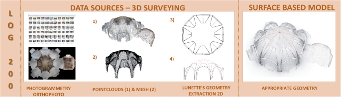
LOG200 (appropriate geometry) turned to the surveying purpose: the orthoimage of the intrados of the St. Bernard’s chapel star vault, the point cloud obtained from the photogrammetric processing (SfM), and the geometric extraction of lunettes borders addressed to support appropriate geometric analysis

LOG300 (Precise Geometry): SCAN-to-BIM model object
The new “As-found HBIM model” (LOD300) with the “Precise Geometry, SCAN-to-BIM model object” (LOG300) devoted to the HBIM modeling phase has been introduced. It can be seen as part of the design development but for its specificity in the HBIM, digitization domain, and complexity issues, it has been kept aside, one step before the design phase (LOD400). Within this phase, as previously described, the choice and adoption of one or more scales to model the object components within the LOG300 can be carried out in function of the context, geometry, and purposes.
LOG300 has been introduced to manage the HBIM modeling phase, particularly the generative modeling phase and represents the level where to build the HBIM enabled models adopting the different GOAs, with their requirements, and GOG specifications, as explained in the “Grades of Accuracy and Grades of Generation for scan-to-BIM model process: specification proposal inheriting the representation scale concept” section, generating NURBS-based model object, starting from the surveying carried out in the LOG200. Thus, the “Grades of Accuracy and Grades of Generation for scan-to-BIM model process: specification proposal inheriting the representation scale concept” section is strictly related to this Level of Geometry where the HBIM-core model is generated.
To detect the richness and creativity of St. Bernard’s chapel vault lunettes and rib construction techniques, different GOAs have been adopted, using both GOA20, GOA50, and GOA10 generating NURBS-based model objects—HBIM enabled—and validating the process through the AVS process and standard deviation analysis in order to support the data transfer to the different BIM uses (Fig. 10). The BIM database needs to be mandatorily populated with the metadata referring to the scales and model accuracy associated to the GOAs adopted for each modeled object orfamilies, part of the HBIM parameters (LOI), which will be transferred, together with the object libraries, in the remote accessible environment (LOD-LOG600).

LOG300 (Precise Geometry, SCAN-to-BIM model object) within the LOD300 (As-found HBIM model). On the left: the HBIM model generation process adopting different GOAs. LOG300 for the HBIM of St. Bernard’s chapel star vault models with different Grades of Accuracy correspondent to the scales (GOA20–50–10) and the data model validation (AVS). On the right, the LOI information process and HBIM parameters with the GOA attributes
LOG400 (HBIM uses—conservation plan)
LOG400 (HBIM uses—conservation plan) within the LOD400 (design development—conservation plan) has been addressed to the conservation plan steps and adapted to the HBIM uses.
When speaking about BIM uses, it means the different uses of BIM for different purposes and within different environments, as in the case of BEM (building energy management), energy efficiency, or structural analysis (BIM to FEA).
In this paper, HBIM uses complain all the steps characterizing the conservation plan, including the analysis of materials and decay, the analysis of the construction technologies and of the stratigraphic units (Building Archaeology), and the integration of diagnostics, as well as inspections using non-destructive techniques (i.e., IRT—InfraRedThermography). Diagnostics and NDT belong to the analytical phase from which the design phase and decision-making are derived with the different items (preservation of the unicity of materials and techniques, implant integrations, structural design, energy efficiency solutions, the design of the eventually new building objects, as a new covering, stairs, and lifts or structural elements reinforcing the existing building structural behavior, and so on).
In recent years, studies have been started to experiment BIM uses in the Digital Heritage (DH) addressing the management of preservation toward HBIM specificity (Baik 2020). They have shown how the generation of an HBIM model can be useful for different types of analysis such as finite element analysis (Korumaz et al. 2017; Barazzetti et al. 2018), energy analysis (Lewis et al. 2015) construction system information modeling, restoration, construction site management (CoSiM) (Trani et al. 2015), and facility management (Pishdad-Bozorgi et al. 2018). In the HBIM of the Collemaggio Basilica (L’Aquila), material and decay analysis were studied with full enable HBIM objects taking into account the complexity of the façade with its stratigraphic units (Brumana et al. 2018a), together with BIM-to-FEA analysis and EE BIM purposes implemented through local heating and the design development of the new covering system in substitution of the crashed one under the earthquake. In this study, NURBS-based BIM objects, which correspond to the material and decay polygons, have been developed in order to connect specific information to each decay areas. In particular, the creation of those sub-elements allows users to understand the characteristics of each area, helping the decision-making process for the restoration. Consequently, the granularity of the generated models (i.e., wall objects built within the LOG300, with GOA20 and GOA50, columns GOA20–10), togheter withthe front decay areas/volumes/stratigraphic unit objects defined within LOG400 and addressed to the metric computation (WBS, work breakdown structure), allowed to accommodate different levels of geometry and accuracy according to the project needs. Figure 11 shows how the new paradigm of the “utility” of scan-to-HBIM models can be oriented according to the analysis one willing to undertake. The use of HBIM models in these simulation and analysis software is considered an added value capable of increasing the BIM-based sub-analysis accuracy and reliability carried out at LOG300.

LOG400 (HBIM uses—conservation plan) within the LOD400 (design development—conservation plan). The HBIM model generated at LOG300 allows users and sub-sequent BIM-based analysis to improve their results using different oriented-model types to perform the decision-making process of the conservation plan, as in the case of the material and decay analysis with the related cost computation and work breakdown structures, BIM-to-FEA or BIM energy models, design development (i.e., implants, new components, new structural elements), and construction site management
The LOG300 and LOG400 are interdependent once to the other and continuously integrated, being the first a model-oriented phase and the second an object-use oriented phase that can also simplify the given models or also enrich them. In this phase, the model can also be simplified or broken down into granular elements according to the needs or subsequent analysis. Consider, for example, the numerical modeling methods which are tools capable of representing, with adequate precision, the geometry of a system, taking into account its stress-strain behaviour and making the necessary calculations within a reasonable time. As is well known, it is possible to classify numerical methods into two large groups: continuous methods and discontinuous methods. Unlike the first method, by modeling a set of discrete and distinct bodies that interact with each other only in case of a mutual contact, the mechanical behaviour of the vehicle is described by tracing the trend of the forces that develop at the points of contact and the movements of the individual elements that compose it. In fact, while in the continuous methods the contacts between elementary units remain unchanged regardless of the response of the model, in the discontinuous ones they are updated at each iteration based on the position and relative movement of the individual elements. Consequently, thanks to this peculiarity, the modeling will have to provide for a further breakdown of the model into elements corresponding to bricks, stones or beams (Banfi 2020). At this level, different GOAs can be adopted including a process addressed to guarantee tools interoperability.
LOG500 (conservation site)
Within LOD500 (construction stage), the LOG500 (conservation site) defines the geometric model as the sum of as-found, and as-designed and as-built layers (Fig. 12). Unlike the other geometry levels, LOG500 represents the geometric and typological function of many data, analyses, and models aimed at the specific purpose of preservation of the architectural heritage. Many professionals are involved in the preservation process, from restorers to structural engineers, who have various requests, so models need to be flexible.

LOG500: conservation site and HBIM management of the interventions of preservations
For this reason, models (from the as-found model to the as-built model) require continuous updating both from a geometric and a semantic points of view. As demonstrated in the LOG400, it is therefore vitally important to combine this wealth in a single digital hub capable of responding to requests for intervention, design, and preservation of the artifact. The LOG500 is defined, but it is not yet considered a praxis in the BIM and HBIM management, even if in Italy, the introduction of BIM for new construction and preservation works was favored by the BIM Decree (Ministerial Decree n. 560 of 1 December 2017) for public buildings in response to the EUPPD Directive (Directive 2014/24/EU). It provides BIM for public procurements depending on the amount of the work until 2023 and for any amount from 2025.
There are still a few cases adopting BIM for the on-site management with an exhaustive as-built BIM documentation. On-site construction level is still missing in the daily restoration and conservation process due to different factors, such as the lack of HBIM skilled on-site workers and the lack of chains that push the companies to adopt the HBIM for fast checks and updating, saving time, and costs.
Research developments for LOG600: Geospatial Virtual Hub with linked HBIM implementation to manage object libraries and a BIM-based collaborative cloud platform
Information technology is the bedrock of our modern world. The modernization of instruments, software, and processes is essential for different disciplines in the AEC sector. Modern and heritagebuildings,historical monuments, and archaeological site digitization, and the availability of their data, represents a compelling added value to improve the IT knowledge of an architectural object, monument, or component. In recent years, following the example of the UK and the “Government Construction Strategy,” many states and government bodies are proposing new forms and solutions-oriented to create “a fully collaborative 3D BIM with all project and asset information, documentation, and data being electronic BS EN ISO19650-2 (2018).” The more data will increase, the more one needs to improve multi-facet access to support co-working and decision-making process. The paper proposes the creation of a 3D environment with data coming from different models that may be originated by a multitude of users, such as BIM experts, professionals (i.e., architects, structural engineers, mechanical engineers, …), practitioners, suppliers, contractor and subcontractors, clients and other consultants, experts and non-experts.
LOG600 (as-built, LLCM, CDE, HUBs) within LOD600 (facility management) is addressed to the management, monitoring, and communication process in the cloud. LOG600 is characterized by a remotely accessed pre-requisite to support multi-actors co-working. It complains the Long Life Cycle Management and Monitoring, VR to xR, and sensor-based communication purposes and it is addressed toward a Common Data Environment, using advanced data sharing semantic–based virtual hubs.
LOG600 generally regards the data sharing of HBIM object models. It is planned to be progressively implemented into the daily management process, in the Life Cycle Cost Management and Monitoring, including VR to xR, and sensor-based monitoring, supported by live applications on the cloud allowing to control the digital twins remotely and relate them to the reality using sensors, in order to support model sharing, monitoring, and communication to different end-users (on-site technicians and operators,experts remotely controlling the data fluxes, but also citizens and tourist for cultural purposes). VR has become a tool for architects to tell a building story without trivializing it and offering different possibilities for sharing the information. Augmented reality is used for on-site virtual tours by using mobile phones or tablets; virtual reality is used for serious games and remote visits, allowing to share heritage across the world. A mix of AR and VR (Mixed Reality), together with other devices, help to share an immersive experience as proven by the novel extended-reality of S. Ambrogio church in Milan (Banfi et al. 2019) and the archaeological site of Bajardo in the Liguria region (Italy) (Banfi 2020).
LOG600 is underemployed nowadays, in the authors’ opinion, it will need to be strongly adopted in the future to avoid data and knowledge dispersion and to support daily maintenance with live digital twins. A workflow from LOG100 to LOG600 is illustrated in Figure 13. A workflow of the implemented platform (Geospatial Virtual Hub and CDE) is illustrated in Fig. 14.

LOG600: the workflow from the LOGs100-500 to holistic data sharing among Object Libraries (LOG600). Once generated the different Objects Libraries (Id_n), such data can be re-used in different ways: Geospatial semantic based Virtual Hubs can support Spatial-Temporal queries, where HBIM Object Libraries can be linked to GEODB HUB through their ID_Code; Common Data Environment can support Life Cycle Management and Monitoring continuously fed up by sensors; a more informed communication by mean of XR (AR/VR/MR) based on these content models can reach a broader public
Following the analysis of St. Bernard’s chapel, an HBIM vault library was created in order to improve the new paradigm of the “re-use” of the digital models, allowing users to share and analyze different types of data coming from different field of knowledge. Figure 13 shows how each Object Library enters in the common space with the different LOGs, each model object with its own Level of Accuracy and Grade of Generation. The (i) new personalized HBIM parameters of the model, (ii) the BIM database extracted once the model has been mapped, and (iii) the exchange formats (proprietary and open) allow connecting the object libraries within new digital solutions: (a) the implementation of a semantic-based Geospatial Virtual Hub (Brumana et al. 2018c) fed up by linked HBIM creating an OpenAccess vault inventoryfor queries across space and time, discovering similarities and mutations of the vaulted systems and (b) BIM-based cloud platform are here presented.
The availability of an increasing number of object libraries will allow comparing such data one over the other. In order to provide a method to combine HBIM single nodes, it has been created a platform that shares the information of HBIM object libraries in a common Geospatial Hub. An application (GEOPAN APP) has been implemented (Previtali and Latre 2018) using a virtual hub to access the different data coming from Open Data maps (current and historical) and other information coming from the HBIM objects libraries linked to the Geospatial Hub: a virtual hub can be considered like a booking flight hub, a semantic-based brokering system able to discover and access (DAB, Discovery and Access Brokering system) different multi-spatial and multi-temporal data collected by the Geographic Open Data through the open links (Nativi et al. 2013). A broker architectural approach, designed and developed in recent research activities for Global Earth Observation (Mazzetti et al. 2015), implemented specific components (the brokers) to perform interoperability actions to interconnect heterogeneous data and systems, provide users with a single point of access to geospatial datasets enabled by new or existing platforms and infrastructures, including INSPIRE-compliant systems and Copernicus services.
The information collected on the single vaults through the HBIM object library feeds the GEODB implemented on the vault typologies and characteristics the semantic-based virtual hub allows the users to query and access the information. The DataBase enriches the granular HBIM data nodes and vice-versa. The GEODB (Geographic DataBase) contains information, such as geographic location, typology of building, description of the vault typology, construction techniques, components of the vaulted system, name of the authors or skilled-workers family, phase of construction within the whole heritage building complex, togheter with information on the scale of HBIM accuracy, surveying scale, and HBIM model scale tolerance (GOAn).
The GEOPAN APP (GEOPAN APP DB Vaults 2020) allows one to add and relate any further information and model formats (as HBIM data, object libraries, 3D model, A360 formats) to each geographic entity (Brumana et al. 2018c). In the St. Bernard’s chapel (Fig. 14), the information refers to other similar vaulted systems in Italy and the Czech Republic, the Italian-Czech family of artists and architects Santini, and the construction techniques of the vaulted system. The goal is to make the multiplicity of data easily available (i.e., drawings, historical documents, photographs, thermal image dataset, HBIM) for cross-queries. The GEOPAN APP allows one to retrieve and compare the different information collected on the different vaulted system with their details (LOD = LOG + LOI) and GOAs in function of the level gained within the different type of research.

The HBIM vault library and its exchange formats for LOG 600 through the Geospatial Hub and the BIM-based cloud platform (upper). The GeopanAPP was implemented within the Geospatial Virtual Hub with the Vault GEODB and linked HBIM object libraries. Queries based on the GeoDB can be performed correlating the different objects libraries (in this case the Plazy St. Bernard Chapel with some star vaults in Northern Italy, and the GOA information)
Common Data Environment: beyond scan-to-BIM models to increase collaborative communication
In the UK, level 2 is also known as Common Data Environment (CDE) or a “federated model” where it is possible to use different models to create a digital hub, giving a complete holistic view of the building.
Assuming that a LOG400 (BIM uses) can best express the concept of model interoperability, it is also useful to consider how this three-dimensional information can be shared. LOG500 and LOG600 introduce the concept of sharing models through CDE, increasing the level of collaborative communication. It should also be considered that in the Digital Cultural Heritage (DCH), historic buildings, archaeological sites, and infrastructures require the management of different information compared to new buildings, i.e., the stratigraphic units of the archaeological sites or the interventions and operations addressed to their preservation. Consequently, in this specific context, it is necessary to underline that CDE should be composed of many data, formats, and models, the latter oriented toward different uses, with the ultimate aim of improving the management of the object over time and allowing different users and operators to access the common space with different commitment and limitations in the data modifications. Therefore, the shared data environment (CDE) should be considered a single source of information used to collect, manage, and share graphical models and non-graphical data in a conventional data format. According to PAS 1192-2: 2013, a CDE may use a project server, an extranet, a file-based retrieval system, or other suitable toolsets.
This concept was subsequently taken up in the Italian standards of UNI 11337: 2017 series, where it took the name of “data sharing environment,” synthetically indicated with ACDat. In the information specifications, the contracting authority must specify its requirements for the ACDat. The following aspects must be satisfied:
-
accessibility by all the actors involved in the process, according to pre-established rules;
-
traceability and historical succession of revisions made to the contained data;
-
support of a wide range of types and formats and their processing;
-
high query flows and ease of access, hospitalization, and extrapolation of data (open data exchange protocols);
-
conservation and updating over time;
-
guarantee of confidentiality and security.
Live monitoring, data remotely accessed, and application connected to BIM
The constant growth of sensors acquiring data requires to be integrated with the BIM data and easily remotely accessible through common devices by operators and not-BIM-skilled workers. This research, inheriting previous experiences, such as the Project Dasher (Autodesk©) and the recent solutions developed through the Autodesk Forge and Revit API platform, shows how a scan-to-BIM model in a CDE can improve the information sharing, from structural and energy monitoring to LOG600 Life Cycle Cost Management and Maintenance Programs.
Thanks to the first development phase, a research project has been carried out to manage live data coming from sensors (HOMeBIM liveAPP: Development of a 4D multi-user Live APP for the improvement of the comfort-efficiency-costs, from a cloud platform that controls the flow of BIM sensors over time - ID 379270). Thanks to this project, it has been possible to create a tool that helps tenants and BIM managers, involved at the different levels of the project (users, decision-makers, planning), to quickly estimate the internal quality of the environments through thermal sensors (i.e., temperature T, humidity). HOMeBIM liveAPP had the objective of creating a live cooperative space between users and the environment (indoor and outdoor) by generating scan-to BIM models to integrate climate parameters, lighting, insulation, and retrofitting. The methodologyand the APP based on live monitoring proposal using the BIM objects libraries can be considered a further step of remote data collection with different appliesin the heritage domain: in the case of vault libraries it can be the micro-climate monitoring.
Nowadays, most buildings are equipped with sophisticated Building Control Systems (BCS) that collect a significant quantity of analysis and data types. These systems support generative design building managers to minimize long-term operational costs ensuring occupants’ comfort. A key challenge of this research was developing a system that organizes, study, and share data for any type of building and infrastructure, extending BIM to the “LOG600: LLCM Life Cycle Cost Management and Monitoring, VR, and sensor-based communication purposes.”
Figure 15 shows the second development phase, which is addressed to allow users to move from a building scale to complex infrastructure, archaeological sites, and mixed reality (VR-AR). It has been implemented an open BIM-based cloud platform that provides real-time building performance throughout the integrated use of advanced technology, such as sensors, open exchange formats such as the IFC, and digital models to evaluate building performance continuously. In this context, a more interactive BIM-based approach has been created to understand how to improve overall operational requirements, future configuration, and managing complex model information. The integration of “sensor BIM objects” into the model made it possible to connect different data flows and simplify the display and reading of complicated graphs, extending BIM value beyond simple Revit objects such as walls, doors, and windows. It was considered to orient the platform to any building during the second development phase. For this purpose, new interfaces and tools are on developing. The availability of Object Libraries data can be re-used by Creative Industries for XR based implementation both for a better informed public and for advanced remotelyaccessible mainteinance programmes.

An open BIM-cloud platform: a Common Data Environment for different BIM uses. The bottom-up methodologic workflow: from building scale to complex scenarios (model and information) with different LOG-LOI: the re-use of live data for the XR based implementation by the Creative Industries for mainteinance purposes and large public knowledge transfer programmes
Conclusion
In the context of Digital Cultural Heritage (DCH) and Heritage Building Information Modeling (HBIM), the article provides novel scan-to-BIM modeling specifications for the generation of HBIM models and their sharing as object library components.
HBIM object libraries have great potential in correlating many data acquired on the single object during the different phases of a conservation project (Level of Development), allowing users to share enriched models objects.
The association of the scale factor to the model allows choosing the most proper model according to the objectives, validating and sharing the modeled object enriched with all the collected information during the data collection and modeling phases.
Thanks to the introduction of the GOA scales concept here and the application of different scan-to-BIM modeling requirements, such as GOG and GOA, the research method can be nowadays considered mature for integrating such guidelines within a standardization process able to support all the actors.
New LOG (100–500) —HBIM orientedas part of the HBIM LOD phases (100–500)—has been proposed to support the preservation phases. The definition of LOGs is not to be confused with the model scales (GOAs) that are part of the different LOGs and can be differentiated in function of the different LOD goals, depending on the multidisciplinary actors’ purposes, and tool limits or capabilities. In particular, LOGs represent the level of detail and information connected to the different phases of developments progressively enriched by the historical reports collection (LOG100), surveying phase (LOG200) and modeling phase (LOG300), inherited by the design development (LOG400) that starts from the analytical phase (i.e., materials and decay analysis, diagnostics processing) addressed to the redaction of the preservation plan, including the HBIM uses (i.e., BIM-to-FEA, BEM, energy design, WBS), untill the conservation site (LOG500). This contribution can represent the first step toward a standardization process within the involved bodies. Since the standardization process (UNI 1137:2017; UNI 1137-3-2017) is still on course of definition, the proposed LOG could be integrated, together with the decay analysis and monitoring of the intervention and the surveying and HBIM modeling phases, supporting data sharing addressed to documentation, conservation process and Life Cycle Management.
The association of the scale to the model object can clarify the “measurability” of the geometric content, allowing users to adopt the proper model (scale) in the function of the needings, avoiding mismatching in the re-use of simplified models coming from reliable surveys but not declaring the scale and tolerance adopted in their generation.
The international debate is mature under the technical skills to start this process in order to guarantee the HBIM management of the multiplicity and specificity of objects, shapes, and arrangements, taking into account the adoption of the different level of detail (high medium low) required by the different purposes.
A LOD600-LOG600 is also proposed to underline the importance of HBIM library management within a collaborative environment through a Geospatial Virtual Hub and a Common Data Environment platform: the Geospatial Virtual Hub, correlating the “informative” models with the linked HBIM object libraries, opens the construction of object library of vaults supporting the discovery, access, and semantic-based query across space and time crawling the richness of information and knowledge gained by the different Levels of Geometry. Other contents can be implemented following the workflow scheme, building a virtual “library,” open and usable by experts and non-experts, supporting comparison among the different objects, with their specificity and analyzing common features across regions and time. Different scales of generation can be taken into account in the re-use avoiding mismatching and wrong interpretation due to the different scales adopted and not to the object represented. The Common Data Environment platform implemented allows access to the HBIM library within an open environment.
Many pending issues need to be further analyzed in the future being. The process is ready to get a consensus and finalize HBIM specifications in the form of Euro codes. This requires sharing the drafted specification among the different actors involved in the process. Moreover, some aspects, here not considered, should be deeper analyzed as the LOI content to be exploited—in parallel to the LOGs—as well as a detailed analysis of the LOG400–500 specificities under the supervision of preservation experts, restorers and multi-disciplinary actors.
The progression of the LODs-LOGs—name and related numbers—here suggested can be merged in case of necessity to encapsulate HBIM within the BIM grid logic (i.e., merging HBIM LOG200 with LOG300), even if we think that the specificity of each domain requires a mature debate taking into account the built environment respect the new building.
Moreover, the process here suggested (selection of proper GOAs and introduction of new and different Levels of Geometry) could be adopted also for other domain fields as INFRA-BIM. The case of BIM addressed to existing infrastructures for maintenance and monitoring purposes requires to introduce specific targeted clear roles in the LOG-LOD definition.
The BIM sequences (LOD-LOG and LOI, and GOA-GOGs), applied to the built environment and needing a clear phase addressed to the on site data collection (LOG200), the modelling (LOG300) the BIM uses (LOG400) and construction site (LOG500) according to the different scales and purposes. .
Copyright is a topic that must be further analyzed in the case of HBIM object libraries data sharing in the clouds: it poses the problem of protecting the creators of the models and defining the property rights (IPR), especially in the case of not-free-for-charge use of the HBIM models and libraries generated and paid by the commitment, establishing how to share and access such models. Another issue that will need to be faced in the growing of object libraries is a common shared vocabulary and terminology, as in the case of vault libraries generated from different subjects and on different geographic areas or typologies, to protect the specificity from one country to another or supporting similarities among different regions.
Change history
18 May 2021
Funding (1st line) should be: Open Access funding provided by Politecnico di Milano within the CRUI-CARE Agreement (and not Open Access funding provided by Politecnico di Milano).
References
AEC (CAN) BIM Protocol (2014) Implementing Canadian BIM standards for the architectural, engineering and construction industry based on international collaboration
AIA (2015) The American Institute of Architects’, BIM Forum, Level of Development (LOD) specification
Attico D, Turrina A, Banfi F, Grimoldi A, Landi A, Condoleo P, Brumana R (2019) The HBIM analysis of the geometry to understand the constructive technique: the use of the trompe volume in a brick vault. ISPRS Ann Photogramm Remote Sens Spatial Inf Sci XLII-2-W11:107–114. https://doi.org/10.5194/isprs-archives-XLII-2-W11-107-2019
Azhar S, Khalfan M, Maqsood T (2012) Building information modelling (BIM): now and beyond. Constr Econ Build 12(4):15–28
Baik AH (2020) Heritage building information modelling for implementing UNESCO procedures challenges, Potentialities, and Issues, Taylor & Francis, ISSN: 9781003036548, https://doi.org/10.1201/9781003036548
Banfi F (2019) HBIM generation: extending geometric primitives and BIM modelling tools for heritage structures and complex vaulted systems. Int Arch Photogramm Remote Sens Spat Inf Sci XLII-2/W15:139–148. https://doi.org/10.5194/isprs-archives-XLII-2-W15-139-2019
Banfi F (2020) HBIM, 3D drawing and virtual reality for archaeological sites and ancient ruins. Virtual Archaeol Rev 11(23):16–33. https://doi.org/10.4995/var.2020.12416
Banfi F, Brumana R, Stanga C (2019) Extended reality and informative models for the architectural heritage: from scan-to-BIM process to virtual and augmented reality. Virtual Archaeol Rev 10(21):14–30. https://doi.org/10.4995/var.2019.11923
Barazzetti L, Brumana R, Della Torre S, Gusmeroli G, Schiantarelli G (2018) Point clouds turned into finite elements: the umbrella vault of Castel Masegra. OP Conf Series: Mater Sci Eng 364:1–8. https://doi.org/10.1088/1757-899X/364/1/012087
Becchi A, Carvais R, Sakarovitch J (2018) L’Histoire de la construction/construction history. Relevé d’un chantier européen/Survey of a European Building Site, vol. I-II, Classiques Garnier, Paris
Bertolini Cestari C (2011) Il Paraboloide. Un’architettura resistente per forma: la volta sottile di Casale, in Atti e Rassegna Tecnica degli Ingegneri e degli Architetti in Torino, Nuova Serie, 65/2
Brumana R, Della Torre S, Previtali M, Barazzetti L, Cantini L, Oreni D, Banfi F (2018a) Generative HBIM-modeling to embody complexity: surveying, preservation, site intervention. The Basilica Di Collemaggio (L’Aquila). Appl Geomatics 10:545–567
Brumana R, Condoleo P, Grimoldi A, Banfi F, Landi AG, Previtali M (2018b) HR LOD based HBIM to detect influences on geometry and shape by stereotomic construction techniques of brick vaults. Appl Geomatics 10:529–543
Brumana R, Condoleo P, Grimoldi A, Landi AG, Attico D, Turrina A, Banfi F, Previtali M (2018c) HBIM feeding OpenAccess vault inventory through GeoDB HUB. In: Ioannides M, Fink E, Brumana R, Patias P, Doulamis A, Martins J, Wallace M (eds) Digital heritage. Progress in cultural heritage: documentation, preservation, and protection. Springer, pp 27–38
Brumana R, Banfi F, Cantini L, Previtali M, Della Torre S (2019) HBIM level of detail-geometry-accuracy and survey analysis for architectural preservation. Int Arch Photogramm Remote Sens Spat Inf Sci XLII-2/W11:293–299. https://doi.org/10.5194/isprs-archives-XLII-2-W11-293-2019
BS EN ISO19650-2 (2018) Organization and digitization of information about buildings and civil engineering works, including building information modelling (BIM). Information management using building information modelling. Delivery phase of the assets
Cavallari-Murat (1963) Static intuition and formal imagination in the space lattices of ribbed gothic vaults. Student Publ School Des 11(2):3–39
Chow L, Graham K, Grunt T, Gallant M, Rafeiro J, Fai S (2019) The evolution of modelling practices on canada's parliament hill: an analysis of three significant heritage building information models (hbim). Int Arch Photogramm Remote Sens Spat Inf Sci
Condoleo P (2018) What hides behind the plaster? Hollow-brick and iron vaults in Europe between the eighteenth and the twentieth century. In: Wouters I et al. (eds), Building knowledge, constructing histories - Proceedings of the Sixth International Congress on Construction History (6ICCH), July 9-13, 2018, Brussels, Belgium, vol. I, 501-508
De l’Orme P (1567) Le premere tome de l’architecture, Fédéric Morel, Paris
Della Torre S, Mannoni T, Pracchi V (1998) Magistri d’Europa. Eventi, Relazioni, Strutture Della Migrazione di Artisti e Costruttori dai Laghi Lombardi, Nodo Libri, Como
Derand F (1643) L’ architecture des voûtes, Sebastien Cramoisy, Paris
Directive 2014/24/EU of the European Parliament and of the Council of 26 February 2014 on public procurement and repealing Directive 2004/18/EC. http://data.europa.eu/eli/dir/2014/24/oj
Eadie R, Browne M, Odeyinka H, McKeown C, McNiff S (2013) BIM implementation throughout the UK construction project lifecycle: an analysis. Autom Constr 36:145–151
Etlin RA (2015) The “strength of vaults”. Proceedings of the Fifth International Congress on Construction History June 2015, Construction history society of America, Chicago, 49-60
Garofalo E (2016) Crociere e lunette in Sicilia e in Italia meridionale nel XVI secolo. Caracol, Palermo
GEOPAN APP DB Vaults, http://geoserver.atlas.polimi.it/ (last accessed 2020.10.22)
Grimoldi A (2009) The “frame vaults” of North Italy between the sixteenth and the eighteenth century. Proceedings of the Third International Congress on Construction History Cottbus, Germany, 20th-24th May, Kurrer KE, Lorenz W, Wetzk V (eds), Brandenburg University of Technology, 753-759
Grimoldi A (2018) The vaulted roof of San Vittore in Milan: an unusual sixteenth-century construction. In: Wouters I et al. (eds), Building knowledge, constructing histories - Proceedings of the Sixth International Congress on Construction History (6ICCH), July 9-13, 2018, Brussels, Belgium, vol. II, 707-714
Grimoldi A, Del Curto D, Landi A, Manfredi C, Valisi L (2013) From rest/cons to en/eff: indoor environment and building preservation. In: Boriani M, Gabaglio R, Gulotta D (eds), Online Proceedings of Conference Built Heritage 2013 - Monitoring conservation and management Milan - Italy, 18-20 November 2013, 1235-1243
Huerta S (2004) Arcos, bóveda y cúpula. Geometria y equilibrio en el cálculo tradicional de estructuras de fábrica, Instituto Juan de Herrera, Madrid
Kalina P (2010) In opere gotico unicos: The hybrid architecture of Jan Blažej Santini-Aichl and patterns of memory in post-reformation Bohemia. Umění/Art 58:42–56
Korumaz M, Betti M, Conti A, Tucci G, Bartoli G, Bonora V, Korumaz A, Fiorini F (2017) An integrated terrestrial laser scanner (TLS), deviation analysis (DA) and finite element (FE) approach for health assessment of historical structures. A minaret case study. Eng Struct 153:224–238. https://doi.org/10.1016/j.engstruct.2017.10.026
Leedy WC (1980) Fan vaulting: a study of form, technology and meaning. Scholar Press, London
Lewis AM, Valdes-Vasquez R, Clevenger C, Shealy T (2015) BIM energy modeling: case study of a teaching module for sustainable design and construction courses. J Prof Issues Eng Educ Pract 141(2):C5014005
Mazzetti P, Latre MÁ, Ernst J, Brumana R, Brauman S, Nativi S (2015) Virtual hubs for facilitating access to open data. In: EGU General Assembly Conference, vol. 17
Ministerial Decree n. 560 of 1 December 2017, http://www.mit.gov.it/normativa/decreto-ministeriale-numero-560-del-01122017
Monti C, Fregonese L, Brumana R, Monti G, Vio E (2006) Complex analyses of surface, modelling and comparison of the 3D orthophoto to the real scale with historical cartography: mosaic surface of basilica of San Marco in Venice. e-Perimetron: 224–244
National Institute Of Building Science, United States. National Building Information Modeling Standard. Version 3 – 2015. www.nationalbimstandard.org
Nativi S, Craglia M, Pearlman J (2013) Earth science infrastructures interoperability: the brokering approach. IEEE J Sel Top Appl Earth Observ Remote Sens 6(3):1118–1129
NBS (National BIM Standard). https://www.nationalbimlibrary.com/en/nbs-bim-object-standard/terms-and-definitions. Accessed 12 Mar 2020
Nobile MR (2013) La stereotomia in Sicilia e nel Mediterraneo, Caracol, Palermo
Palacios Gonzalo JC (1990) Trazas y cortes de cantería en el Renacimiento español, Ministerio de cultura, Instituto de conservación y restauración de bienes culturales, Madrid
PAS 1192-2 (2013) Specification for information management for the capital/delivery phase of construction projects using building information modelling
Pérouse de Montclos J-M (2013) L’architecture à la française: du milieu du XV siècle à la fin du XVIII siècle, 3rd edn. Picard, Paris
Pishdad-Bozorgi P, Gao X, Eastman C, Self AP (2018) Planning and developing facility management-enabled building information model (FM-enabled BIM). Autom Constr 87:22–38
Previtali M, Latre MÁ (2018) A brokered virtual hub approach for the generation of web applications based on historical maps. Appl Geomatics 10:453–472. https://doi.org/10.1007/s12518-018-0235-1
Previtali M, Brumana R, Banfi F (2020) Existing infrastructure cost effective informative modelling with multisource sensed data: TLS, MMS and photogrammetry. Appl Geomatics. https://doi.org/10.1007/s12518-020-00326-3
Sammartano G, Spanò A (2018) Point clouds by SLAM-based mobile mapping systems: accuracy and geometric content validation in multisensor survey and stand-alone acquisition. Appl Geomatics 10:317–339. https://doi.org/10.1007/s12518-018-0221-7
Stanga C, Hasníková H, Previtali M, Brumana R, Grimoldi A, Banfi F (2019) The assessment of the baroque vault construction technique by Scan-to-BIM process: St. Bernard’s chapel in the Plasy monastery. Int Arch Photogramm Remote Sens Spat Inf Sci XLII-2/W15:1127–1134. https://doi.org/10.5194/isprs-archives-XLII-2-W15-1127-2019
Suwardhi D, Menna F, Remondino F, Hanke K, Akmalia R (2015) Digital 3D Borobudur-Integration of 3D surveying and modeling techniques. Int Arch Photogramm Remote Sens Spat Inf Sci 40(5):417
Trani ML, Cassano M, Todaro D, Bossi B (2015) BIM level of detail for construction site design. Procedia Eng 123:581–589
Tucci MG, Rihal S, Betti M, Conti A, Fiorini L, Kovacevic VC, Bartoli G (2019) Ground based 3D modelling (photogrammetry and tls) - survey, documentation and structural assessment of xx century cultural heritage in india - a case study of the masonry vaults in Dehradun. Int Arch Photogramm Remote Sens Spat Inf Sci XLII-2/W11:1105–1111. https://doi.org/10.5194/isprs-archives-XLII-2-W11-1105-2019
UNI 1137 (2017) Edilizia e opere di ingegneria civile - Gestione digitale dei processi informativi delle costruzioni
Vitali M, Spallone R, Carota F (2019) Parametric modeling as a tool of analysis and interpretation of built heritage: the case study of complex Baroque vaults. In: Ippolito A, Inglese C (eds) Analysis, conservation, and restoration of tangible and intangible cultural heritage. IGI Global, Hershey, pp 366–401
Volk R, Stengel J, Schultmann F (2014) Building Information Modeling (BIM) for existing buildings—literature review and future needs. Autom Constr 38:109–127
Wang X, Xiao J, Wang Y (2016) Research of plane extraction methods based on region growing. Int Conf Virtual Real Vis. https://doi.org/10.1109/ICVRV.2016.56
Wendland D (2008) Lassaulx und der Gewölbebau mit selbsttragenden Mauerschichten. Neumittelalterliche Architektur um 1825-1848, Michael Imhof Verlag, Petersberg
Wendland D (2014) Reverse Engineering und Experimentelle Archäologie – Forschungen zu Bau, Planungsprinzipien und Entwurfskriterien spätgotischer Zellen gewölbe. In: Schröck K, Wendland D (eds) Traces of Making. Entwursfprinzipien von spätgotischen Gewölbe / Shape, Design and Construction of Late Gothic Vaults, Michael Imhof Verlag, Petersberg, pp 11–37
Yang X, Lu YC, Murtiyoso A, Koehl M, Grussenmeyer P (2019) HBIM modeling from the surface mesh and its extended capability of knowledge representation, ISPRS Int. J Geo-Inf 8:301. https://doi.org/10.3390/ijgi8070301
Acknowledgments
The authors thank the employees working in the Plasy Monastery for their kindness and interest in this research and the National Heritage Institute in the Czech Republic for their cooperation. Special thanks to the coordinator of the POLIMI SSBAP Specialization School, Prof. A. Grimoldi, for his valuable suggestions and Hana Hasníková from the Academy of Sciences of the Czech Republic hosted as visiting researcher at the DABClab GIcarus, Politecnico di Milano.
Funding
Open Access funding provided by Politecnico di Milano within the CRUI-CARE Agreement. The GAMHer project supported this work: Geomatics Data Acquisition and Management for Landscape and Built Heritage in a European Perspective, PRIN, Progetti di Ricerca di Rilevante Interesse Nazionale – Bando 2015, Prot. 2015HJLS7E.
Author information
Authors and Affiliations
Corresponding author
Rights and permissions
Open Access This article is licensed under a Creative Commons Attribution 4.0 International License, which permits use, sharing, adaptation, distribution and reproduction in any medium or format, as long as you give appropriate credit to the original author(s) and the source, provide a link to the Creative Commons licence, and indicate if changes were made. The images or other third party material in this article are included in the article's Creative Commons licence, unless indicated otherwise in a credit line to the material. If material is not included in the article's Creative Commons licence and your intended use is not permitted by statutory regulation or exceeds the permitted use, you will need to obtain permission directly from the copyright holder. To view a copy of this licence, visit http://creativecommons.org/licenses/by/4.0/.
About this article

Cite this article
Brumana, R., Stanga, C. & Banfi, F. Models and scales for quality control: toward the definition of specifications (GOA-LOG) for the generation and re-use of HBIM object libraries in a Common Data Environment. Appl Geomat 14 (Suppl 1), 151–179 (2022). https://doi.org/10.1007/s12518-020-00351-2
Received:
Accepted:
Published:
Issue Date:
DOI: https://doi.org/10.1007/s12518-020-00351-2