
Abstract
During continuous casting, electromagnetic braking (EMBr) is a widely used technology to improve the quality of steel product. The EMBr technology takes benefit of the generation of Lorentz forces that are induced by the interactions of melt flow with externally applied magnetic fields. In the present paper we propose and investigate a new type of EMBr, named vertical-combined electromagnetic braking (VC-EMBr) in application to the Compact Strip Production (CSP) thin slab continuous casting mold. The unique characteristic of the VC-EMBr lies in the fact that two new pairs of vertical magnetic poles (VMPs) are located adjacent to the mold narrow faces on the basis of Ruler-EMBr. To determine the braking effect of the VC-EMBr, the influence of the installation position of the VMPs on the flow, heat transfer and solidification behaviors of ultra-low carbon steel in a 1500 × 70 mm CSP funnel-type mold is numerically solved. The fluid-flow-related phenomena of three casting cases in the CSP mold, i.e., No-EMBr, Ruler-EMBr, and VC-EMBr, are further investigated numerically to evaluate the metallurgical capability of the VC-EMBr, including the quantitative evaluation of level fluctuation, heat transfer, and shell growth at a casting speed of 4.5 m/min. The parametric study shows that for the CSP mold with width of 1500 mm, the optimal braking effect of the VC-EMBr can be obtained when the VMPs are located at 50 mm from the narrow face of the mold. With this adjustment, the magnitude of the maximum surface velocity is reduced by 70 pct when compared to the case of p1 = 0 mm. This reduction can decrease the heat loss in the upper recirculation region of the CSP mold and promote the homogeneity of the temperature field therein. In addition, the evaluation results show that the newly proposed VC-EMBr provides more obvious technological advantages than the traditional Ruler-EMBr in application to the CSP mold with a bifurcated nozzle. For the VC-EMBr, the horizontal magnetic poles (HMPs) keep the same advantage as the Ruler-EMBr in providing a good protection against excessive downward impact of the molten steel. On the other hand, the VMPs overcome the disadvantage that the Ruler-EMBr cannot well suppress the upward backflow in the CSP mold. For instance, by applying a magnetic flux density of 0.3 T, the VC-EMBr has a better capability to reduce the maximum amplitude of the level fluctuation by 83.8 pct and increase the average surface temperature of the molten steel from 1803.6 K to 1804.5 K when compared to the case of Ruler-EMBr. This variation can well prevent surface defects related to the level fluctuation, such as slag entrapment and mold powder freezing. On this basis, it can be seen that the industrial application of the VC-EMBr in the CSP mold can benefit from these findings.
Introduction
Recently, thin slab casting technique has been rapidly developed and extensively adopted in metallurgical production due to its advantages of high efficiency, low investment, low energy consumption, and near-net-shape.[1,2,3] However, in the process of thin slab continuous casting, if melt flow in mold cannot be controlled within optimal ranges for a given thin slab caster, there are still some defects such as inclusions re-entrainment, surface cracks, and oscillation marks.[4,5,6,7,8] Therefore, to improve thin slab continuous casting process, it is indispensable to optimize the process parameters related to the melt flow in the mold.[9] Cukierski et al.[10] indicated that an applied magnetic field has great potential in improving the ability to control the melt flow in the mold. Nevertheless, the premise is to combine the operation parameters such as SEN (submerged entry nozzle) geometry, SEN depth, mold size and casting speed, etc. Therefore, together with the optimized parameters, the application of electromagnetic braking (EMBr) provides an innovative and efficient tool for controlling the melt flow in the mold, thus reducing the occurrence of surface defects on the thin slab.[6] The principle of EMBr is the interaction between a static magnetic field and a moving, electrically conductive fluid, thus producing a braking force (i.e., Lorenz force) in the opposite direction of the melt velocity.[11,12,13,14] However, the size, the number, the shape, and the position of magnetic poles are crucial for the braking efficiency of EMBr.[15,16,17] By that, to maintain quality and increase production for the thin slab given caster, it is of great significance to optimize the configuration and electromagnetism parameters of EMBr.
Generally, two types of EMBr configurations have been implemented into industrial slab casters, including Ruler-EMBr and Double-Ruler-EMBr.[18,19,20,21,22,23,24] The Ruler-EMBr consists of only one pair of horizontal magnetic poles (HMPs), which are arranged below the SEN and positioned flush with the entire wide sides of the mold. However, the Ruler-EMBr has a serious limitation in the application of thin slab continuous casting. The Lorentz force produced by the Ruler-EMBr cannot well control molten steel flow in the meniscus region, resulting in random fluctuations in surface shape and excessive magnitudes of surface velocity. This drawback can increase the risk of mold flux entrainment into the molten pool, especially for high-speed continuous casting of thin slab.s[17,24] Singh et al.[25] indicated that the HMPs placed below the SEN can induce unsteady flows in the mold. Chaudhary et al.[26] also demonstrated a similar effect on transient turbulent flow in steel continuous casting with the Ruler-EMBr. For this reason, the Double-EMBr on the basis of the Ruler-EMBr adds another pair of HMPs at the position of mold top surface, with the aim to better strengthen the stabilization of meniscus fluctuation. However, the Lorentz force generated by the Double-EMBr can excessively suppress the molten steel flow in the meniscus region, which can increase the possibility of meniscus freezing.[27] A related study based on a large eddy simulation (LES) model was performed by Cho et al.,[28] who found that the application of Double-Ruler-EMBr in a typical commercial caster can excessively prevent deformation of the surface profile.
In view of the deficiency of two EMBrs mentioned above, a new type of EMBr named Vertical-Combined Electromagnetic Braking (VC-EMBr) is proposed by the current authors (Figure 1).[29] The VC-EMBr is designed to have two pairs of vertical magnetic poles (VMPs) near the narrow sides of mold and one pair of HMPs below the SEN. The HMPs are parallel to the wide sides of mold, and their configurations are similar to those of the Ruler-EMBr. With the VC-EMBr, the generated distribution of Lorentz forces contributes to both a suppression of the impact of upward backflow on the meniscus and a control of the molten steel flow in the recirculation region of mold. As a result, the VC-EMBr makes it possible to control the molten steel flow in the mold within proper ranges.

Schematic of the Ruler-EMBr equipment installed on the CSP mold: (a) geometric model of the Ruler-EMBr and (b) dimensions of the Ruler-EMBr
Considering the limitation of physical modeling and the harsh environment of continuous casting, in the present study mathematical modeling is chosen to quantify the effect of VC-EMBr on the thin slab continuous casting. As an effective and convenient tool, mathematical modeling has been widely utilized to simulate fluid flow, heat transfer, and solidification in continuous casting mold.[30] For example, Harada et al.[18] compared the braking effect of Local-EMBr and Ruler-EMBr on the fluid flow in the mold. Singh et al.[23] performed an extensive simulation study to elaborate turbulent fluctuations in a typical commercial caster with Double-Ruler. Vakhrushev et al.[1] employed an enthalpy-based mixture solidification model to study the interaction between turbulent flow and solidified dendritic mushy zone in a thin slab continuous casting mold. Aboutalebi et al.[31] applied a computational fluid flow model to investigate turbulent flow, solidification, and evolution of macroscopic segregation in a continuous billet caster.
In view of the universality of mathematical modeling, the authors utilized the numerical simulation method to investigate three-dimensional (3-D) electromagnetic field distribution and multiphase transport behaviors, including the molten steel flow, heat transfer, and solidification in the CSP thin slab continuous casting mold with the VC-EMBr. In addition, to evaluate the metallurgical capability of the VC-EMBr equipment, the simulation results of multiple phenomena between the Ruler-EMBr and VC-EMBr in the CSP mold were compared and analyzed in this article. The layout of this article is organized as follows. Details of the Ruler-EMBr and VC-EMBr configurations are given in Section II. Mathematical formulas and casting conditions are presented in Section III. The current study is conducted for the following casting conditions: a SEN depth of 255 mm, a SEN port angle of − 50 deg, a casting speed of 4.5 m/min, and a magnetic flux density of 0.3 T. The computational model is validated in Section IV and the results of the multiple phenomena between the Ruler-EMBr and VC-EMBr in the CSP mold are discussed in Section V. Finally, the output of this study is concluded in Section VI.
VC-EMBR and Ruler-EMBR Configurations
Figures 1 and 2 show two types of EMBr equipment, i.e., the Ruler-EMBr and VC-EMBr, respectively. As shown in Figure 1, the Ruler-EMBr has a pair of HMPs, which cover the entire wide sides of CSP mold. The HMPs with two sets of electrified coils are installed horizontally below the SEN, with the aim to control the molten steel flow in the lower recirculation region of CSP mold. Besides, the upper surface of HMPs is positioned at 550 mm below the top surface of mold, and the height of HMPs is 200 mm. As shown in Figure 2, the configuration of VC-EMBr is characterized by a U-shaped. On the basis of the Ruler-EMBr, the VC-EMBr has additional two pairs of VMPs along the height direction of the CSP mold, which are connected with the upper edge of HMPs. The VMPs are installed vertically near the narrow sides of CSP mold, with the aim to stabilize meniscus fluctuation and prevent mold flux entrapment. In addition, the width and height of the VMPs are 160 and 550 mm, respectively.

Schematic of the VC-EMBr equipment installed on the CSP mold: (a) geometric model of the VC-EMBr and (b) dimensions of the VC-EMBr
Mathematic Formulation and Computational Conditions
Basic Assumptions
During thin slab continuous casting, the metallurgical process of molten steel flow, heat transfer and solidification in the mold is extremely complicated. In order to facilitate the establishment of a 3-D multi-physical field coupling mathematical model, the following assumptions are made for the steady-state solidification process of thin slab continuous casting.
-
(a)
The molten steel in the mold is considered as a homogeneous incompressible Newtonian fluid with constant thermo-physical properties.[2,24]
-
(b)
The effects of phase transformation, solidification shrinkage, and crystal morphology at solidification front on the molten steel flow in the mold are not considered[32].
-
(c)
The effect of oscillation and negative taper of the mold is ignored[32].
-
(d)
The electromagnetic characteristics of molten steel are homogeneous and isotropic[24].
Mathematic Models
In the current research, the Reynolds-averaged Navier–Stokes k−ε turbulence model, solidification model together with magnetohydrodynamic (MHD) model are performed to couple calculation on the flow field, temperature field, solidification field, and electromagnetic field in the CSP mold.[1,24,32,33,34,35] The related equations of mathematical models are solved using ANSYS® Fluent software, which is based on the finite volume method.
-
(a)
Continuity equation
$$ \nabla \cdot \left( {\rho {\varvec{v}}} \right) = 0, $$(1)where ρ is the molten steel density (kg m−3) and v dd vector (m s−1).
-
(b)
Momentum equation
$$ \nabla \cdot \left[ {\rho \left( {\varvec{v} \otimes \varvec{v}} \right)} \right] = \nabla \cdot \left[ {\mu _{{{\text{eff}}}} \left( {\nabla \varvec{v} + \nabla \varvec{v}^{T} } \right)} \right] - \nabla p + \varvec{F} + \varvec{f} + S_{{\text{m}}},$$(2)where μeff is the effective viscosity of molten steel (kg m−1 s−1), p is pressure (Pa), F is Lorentz force density (N/m3), f is thermal buoyancy force density (N/m3), and Sm is momentum source term.
-
(c)
Turbulence model
The Reynolds-averaged Navier–Stokes (RANS) k−ε turbulence model is one of the most extensive turbulence models to meet the requirements in engineering.[4,31] In comparison with other two-equation turbulence models, the RANS k−ε turbulence model considers a laminar sub-layer to calculate turbulent levels in liquid–solid mushy region.[31,33,34,35] Based on this, to better predict the solidification process of continuous casting slabs, the RANS k−ε turbulence model is employed for describing the comprehensive metallurgical behavior of molten steel in the CSP mold. The governing equations for the turbulence kinetic energy and the turbulence dissipation rate have been proposed by Launder and Sharma and write as follows:[7]
$$ \nabla \cdot \left( {\rho {\varvec{v}}k} \right) = \nabla \cdot \left[ {\left( {\mu + \frac{{\mu_{{\text{t}}} }}{{\sigma_{k} }}} \right)\nabla k} \right] + G_{{\text{k}}} - \rho \varepsilon + \rho D + S_{{\text{k}}} , $$(3)$$ \nabla \cdot \left( {\rho {\varvec{v}}\varepsilon } \right) = \nabla \cdot \left[ {\left( {\mu + \frac{{\mu_{{\text{t}}} }}{{\sigma_{{\upvarepsilon }} }}} \right)\nabla \varepsilon } \right] + C_{\rm{1}} f_{\rm{1}} G_{{\text{k}}} \rho \frac{\varepsilon }{k} - C_{2} f_{2} \rho \frac{{\varepsilon^{2} }}{k}\rho \varepsilon + \rho E + S_{{\upvarepsilon }} , $$(4)where μt is turbulent viscosity (kg m−1 s−1), k is turbulent kinetic energy (m2 s−2), ε is turbulent dissipation rate (m2 s−3), Sk and Sε are turbulence source terms in turbulence kinetic energy equation and dissipation rate equation, respectively. In addition, the coefficients and other additional terms in the turbulence equations can be found in several literatures.[3,7,27,31,33,34,35]
During solidification, the loss of momentum and turbulent kinetic energy is added to the momentum equation and turbulent equation in the form of source terms. The expressions of source terms in the momentum and turbulence equations are expressed as follows[36]:
$$ S_{k\left( \varepsilon \right)} = \frac{{\left( {1 - f_{l} } \right)^{2} }}{{\left( {f_{l}^{3} + \xi } \right)}}A_{{{\text{mush}}}} k\left( \varepsilon \right), $$(5)$$ S_{\rm{m}} = \frac{{\left( {1 - f_{l} } \right)^{2} }}{{\left( {f_{l}^{3} + \xi } \right)}}A_{{\rm{mush}}} \left( {{\varvec{v}} - {\varvec{v}}_{{\text{c}}} } \right), $$(6)where Amush is mushy region constant, and the constant ξ = 0.001 is used to prevent division by zero.
-
(d)
Solidification model
In the present study, an enthalpy-porous medium method is employed to investigate the solidification behavior of molten steel in the CSP mold. Different from the effective heat capacity method, this method treats the liquid–solid mushy region as a porous zone and utilizes the energy equation to solve the enthalpy value of nodes in computational domain.[2,37] The energy equation is given as follows:
$$ \nabla \cdot \left( {\rho {\varvec{v}}H} \right) = \nabla \cdot \left( {k_{{\rm{eff}}} \nabla T} \right) - \nabla \cdot \left( {\rho f_{l} {\varvec{v}}\Delta H_{f} } \right) - \nabla \cdot \left[ {\rho f_{s} \left( {{\varvec{v}} - {\varvec{v}}_{\rm{c}} } \right)\Delta H_{f} } \right], $$(7)where H is the total specific enthalpy of mushy region (kJ kg−1), ΔHf is the specific latent heat of molten steel (kJ kg−1), keff is the effective thermal conductivity of molten steel (W m−1 K−1), fl is liquid fraction, and fs is solid fraction.
Here, the effective thermal conductivity keff and the liquid fraction fl are given by the following equations.
$$ k_{{\rm{eff}}} = k_{\rm{l}} + \frac{{\mu_{t} }}{{\rm{Pr}_{t} }} \cdot C_{{\text{p}}} \cdot \left( {1 - f_{{\text{s}}} } \right), $$(8)$$ f_{{\text{l}}} = 1 - f_{{\text{s}}} = \left\{ {\begin{array}{*{20}l} 0 & {T < T_{{\text{s}}} } \\ {T_{l} - T_{{\text{s}}} } & {T_{{\text{s}}} \le T \le T_{{\text{l}}} } \\ 1 & {T > T_{{\text{s}}} } \\ \end{array} } \right., $$(9)where kl is laminar thermal conductivity (W m−1 K−1), Prt is turbulent Prandtl number, Tl is liquid temperature (K), and Ts is solid temperature (K).
-
(e)
MHD model
The magnetic induction method is employed to calculate the induced current and Lorentz force, both of which are derived from Ohm’s law and Maxwell’s equations.[38] The induced current density J is deduced from the following equation.
$$ {\varvec{J}} = \frac{1}{\mu }\nabla \times {\varvec{B}}\rm{,} $$(10)where B is the total magnetic field, which consists of the applied magnetic field B0 and the induced magnetic field b. The magnetic field b is induced when the molten steel passes through the applied magnetic field B0.
$$ \left( {v \cdot \nabla } \right) \cdot b = \frac{1}{\mu \sigma }\nabla^{2} b + \left( {B \cdot \nabla } \right) \cdot v - \left( {v \cdot \nabla } \right) \cdot B_{0} $$(11)The Lorentz force as additional force in the momentum equation is given by:
$$ F = J \times B $$(12)
Computational Domain and Mesh
In the simulation, the investigated object is a funnel-shaped CSP mold with an enlarged opening area in the upper region. One-half volume of the CSP mold is considered due to the geometric symmetry. Melt flow in the mold domain, including a bifurcated SEN (Figure 3), a continuous casting mold, and a part of the secondary cooling zone, is calculated. The computational domain and the mesh system of CSP mold is shown in Figure 4. A local mesh refinement method is used close to the mold wall and free surface. The whole computational domain is approximately divided into 430,000 hexahedral cells. This value is validated through a grid independence test to guarantee the computational accuracy. The test is carried out through three hexahedral cells as listed in Table I. As can be seen, the test results indicate that even the number of hexahedral cells in the mesh M1 (430,000) is increased to about 2.2 times, the relative error of computed shell thickness at the mold exit is much less than 5 pct.[31] Therefore, considering the balance between computational accuracy and cost, M1 is selected for the present computation.

Schematic of the SEN in the CSP mold: (a) geometric model of the SEN and (b) dimensions of the SEN

Schematic and mesh to be based on the geometry: (a) schematic of the CSP mold and (b) mesh of the CSP mold
Computational Conditions
On the premise of making the simulation results reasonable, the computational conditions in the whole computational domain can be classified as below.
-
(a)
Boundary conditions
During initialization, the inlet temperature was set as 1828 K with the superheat of 298 K, and the inlet velocity is calculated based on casting speed. The top surface of mold is set as a free surface with a free-slip condition, and adiabatic boundary condition is employed in the heat transfer calculation process. The center of mold wide face is defined as a symmetry plane, in which velocity components perpendicular to the symmetry plane and normal gradients of other variables are set to zero. Walls of the mold and the SEN are provided as electrically insulating walls with non-slip conditions.[2,3,4] The velocity components perpendicular to all the walls and the normal gradients of other variables are taken as zero. In addition, heat flux condition is considered for the cooling condition of the mold walls, and convection heat exchange is adopted as a boundary condition of the mold walls in the secondary cooling zone.[2,36] The bottom of computational domain is set as an outlet, which is defined as an outflow condition. The melt flow at the outlet is assumed as a fully developed flow, and the normal gradients of all variables are equal to zero.
-
(b)
Pull velocity conditions
Due to the complex geometric structure of funnel surface in the CSP mold, deformation such as extrusion or stretching is easy to occur during solidification. Therefore, to ensure the formed solidified shell move smoothly along the casting direction, the pull velocity of solidified shell in funnel-shaped region satisfies the following relationship[1,2].
$$ v_{{\rm{surface,}j}} = \left| {{\varvec{v}}_{\rm{c}} } \right|\frac{{{\varvec{n}}_{{\text{z}}} - \left( {{\varvec{n}}_{{\text{z}}} - {\varvec{n}}_{{\text{f}}} } \right) \cdot {\varvec{n}}_{{\text{f}}} }}{{\left| {{\varvec{n}}_{{\text{z}}} - \left( {{\varvec{n}}_{{\text{z}}} - {\varvec{n}}_{{\text{f}}} } \right) \cdot {\varvec{n}}_{{\text{f}}} } \right|}}, $$(13)where, vsurface,j is the moving speed of solidified shell along the j direction of funnel-curved surface, |vc| is the casting speed, nz and nf are unit vectors: nz represents a vector in the direction of casting, nf represents a normal vector to the funnel-curved surface. The calculated pull velocity on the funnel-curved surface of CSP mold is shown in Figure 5, which presents the continuously converged movement of strand shell on the shape variation of funnel.
Fig. 5 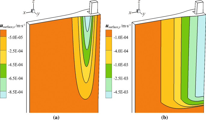
Components of pull velocity on the wide face of mold: (a) X-velocity and (b) Y-velocity

Physical Properties and Casting Conditions
The cast steel used in this model is ultra-low carbon steel, which is widely used in engineering structures. The physical properties of the steel and the casting conditions related to the present calculation are listed in Table II.
Model Validation
Electromagnetic Field Model
The electromagnetic field calculation method used in this study has been verified by the author’s research group on the VC-EMBr slab mold. The results of electromagnetic field measurement and numerical simulation in the VC-EMBr slab mold are shown in Figure 6. As can be seen, with the use of identical geometry and parameters, the numerical results solved by the author are in good agreement with the measured results. In this article, the same mathematical model and solution method are used to solve the distribution of electromagnetic field in the VC-EMBr CSP mold. Therefore, it can be speculated that the numerical model adopted in this study has a reasonable accuracy.

Distribution of magnetic flux density in the slab mold: (a) schematic of the VC-EMBr equipment, (b) magnetic flux density distribution along the direction of the mold width, and (c) magnetic flux density distribution along the direction of the mold thickness
Fluid Flow and Level Fluctuation Models
In our research group, physical experiments with low melting point alloy (Pb–Sn–Bi) as the medium were used to verify the accuracy of the molten steel flow and level fluctuation in the slab mold.[39] The cross-sectional dimension of the slab mold is shown in Figure 6. The experimental and numerical results of level fluctuation heights in the slab mold are shown in Figure 7. In the experiment, the Froude number and Stuart number are adopted as a similarity rule, and the scale of the experiment to the simulation is 0.2. Based on this, the casting conditions are performed with a SEN port angle of −15 deg, a SEN depth of 45 mm (actual: 225 mm), a casting speed of 0.8 m/min (actual: 1.8 m/min), and a magnetic flux density of 0.41 T (actual: 0.3 T). Furthermore, the wave amplitude λ is based on Reference [40]. As shown in Figure 7, the numerical results of wave amplitudes in the slab mold are in good overall agreement with the experimental results. In this study, the same solution method is used to solve the molten steel flow and level fluctuation in the CSP mold under the effect of the VC-EMBr. Therefore, it can be considered that the solution method adopted in the current simulation research has relatively reasonable accuracy.

Level fluctuation heights in the mold: (a) experiment results of level fluctuation heights and (b) experimental and numerical results of wave amplitudes
Results and Discussion
In the current research study, three conditions in the CSP mold are simulated, i.e., (a) No-EMBr, (b) Ruler-EMBr, and (c) VC-EMBr, with all other parameters remain the same. For the Ruler-EMBr and VC-EMBr, the maximal magnetic flux density in the central plane is 0.3 T. The simulation results of the level fluctuation, multiple fields (i.e., electromagnetic field, flow field, temperature field), and solidification, are presented in the following sections.
Characteristics of Electromagnetic Field in CSP Mold with EMBrs
Figure 8 shows the distributions of the magnetic field, induced current, and Lorenz force in one-half of the CSP mold region with the Ruler-EMBr. Figure 8(a) shows that the magnetic field in the direction of the mold height decreases to both sides of the magnetic pole edge with the Ruler-EMBr. Figures 8(b) and (c) show that the induced current and the Lorentz force in the impingement region of the jet flow are greater than those in the upper recirculation region of the mold. Such results imply that the magnetic field generated by the Ruler-EMBr can well act on the impingement region of the jet flow, which in turn leads to a higher-induced current and Lorentz force therein.

Distributions of (a) total magnetic field, (b) induced current density, and (c) Lorentz force in the central plane with the Ruler-EMBr
Figure 9 shows the distributions of the magnetic field, induced current, and Lorenz force in one-half of the CSP mold region for different VMP positions of VC-EMBr. As can be seen, the magnetic field formed by the VC-EMBr is mainly concentrated in three key regions: the jet impact region, upward backflow region and meniscus region near the narrow face of the mold. Combined with the flow characteristics of the molten steel in the mold, the jet flow discharged from the nozzle exit is firstly decelerated by the horizontal magnetic field and forms an upward stream. Then, the upward stream flows to the SEN and is braked again by the vertical magnetic field (see Figure 11). This indicates that the vertical magnetic field formed by the VC-EMBr is an important factor to control the molten steel flow in the upward backflow region.

Distributions of (a) total magnetic field, (b) induced current density, and (c) Lorentz force in the central plane with the VC-EMBr
As shown in Figure 9(a), the variation of the position of the VMPs is crucial for the braking efficiency of the VC-EMBr. For the fixed position of horizontal magnetic poles (HMPs), with the position of the VMPs moving from p1 to p2, the attenuation of the vertical magnetic field moving towards the SEN is obviously weakened. This means that the braking efficiency of the VC-EMBr on the molten steel flow in the upward backflow region can be obviously improved. Correspondingly, the surface velocity can become remarkably stable when the position of the VMPs moves from p1 to p2 (see Figure 13). However, when the position of the VMPs continues to move toward p3, the values of the magnetic field as well as the induced current and Lorentz force in the upward backflow region is no longer increased significantly. This indicates that the braking effect of the VC-EMBr on the upward backflow close to the top surface of the mold can be changed slightly when the position of the VMPs moves from p2 to p3 (see Figure 11). Accordingly, there can be no significant change in the magnitude of the surface velocity (see Figure 13). Moreover, with the application of the VC-EMBr, it also can be found that the magnetic field based on the HMPs can be guided to the meniscus region through the VMPs, which leads to the slow attenuation of the magnetic field in the upper recirculation region of the mold. For instance, in the case of a VMP position of p1 = 0 mm, the maximum magnetic flux density in the meniscus region near the narrow face of the mold reaches 0.28 T, while the respective value with the Ruler-EMBr is only 0.01 T. As shown in Figures 9(b) and (c), due to the arrangement of magnetic poles with special structure, the induced current and the Lorentz force produced by the VC-EMBr are far greater than those generated by the Ruler-EMBr in the upper recirculation of the mold, especially in the impinging region of the jet flow covered by the VMPs. The results above show that in the upper recirculation region of the CSP mold the electromagnetic performance of the VC-EMBr is better than that of the Ruler-EMBr.
Effect of VMP Positions of VC-EMBr on Melt Flow, Heat Transfer, and Solidification in CSP Mold
During continuous casting, the position of magnetic poles is crucial for the efficiency of the EMBr equipment. Any inappropriate position of magnetic poles causes the occurrence of surface defects related to the level fluctuation, such as slag entrainment, inclusions and bubbles entrainment, and meniscus freezing, etc.[28] Therefore, to avoid surface defects and improve braking efficiency, it is essential to seek an appropriate position of magnetic poles. In the present section, to obtain the optimal braking effect of the VC-EMBr, the effect of the variation of the VMPs on the melt flow, heat transfer, and solidification in the CSP mold is investigated. Figure 10 shows the schematic diagram of the VC-EMBr with three types of VMPs positions in the CSP mold. For the VC-EMBr, on the premise of keeping the position of HMPs unchanged, the position of the VMPs is defined as below: (1) p1 = 0 mm (hereinafter, p1), (2) p2 = 50 mm (hereinafter, p2), and (3) p3 = 100 mm (hereinafter, p3). Here, p is the distance from the outer edge of the VMPs to the narrow sides of the mold.

Schematic diagram of three types of positions of VMP: (a) p1 = 0 mm; (b) p2 = 50 mm; (c) p3 = 100 mm
Figure 11 shows the distribution of the flow field in the central plane of the CSP mold with three positions of VMPs. As shown in Figure 11, with the position of the VMPs moving from p1 to p3, the braking effect of the VC-EMBr on the molten steel flow in the lower recirculation region of the CSP mold is basically the same due to the fixed position of HMPs. In contrast, the braking effect on the backflow in the upper region is apparent. In comparison with the condition of p1, due to the variation of initial braking position, the upward backflow is restricted to a smaller space with the conditions of p2 and p3. This restriction is conductive to controlling the surface flow of the molten steel in the center region of the slab.

Distribution of flow field in the central plane with VC-EMBr: (a) p1 = 0 mm, (b) p2 = 50 mm, and (c) p3 = 100 mm
Figure 12 shows the distribution of temperature field in the central plane of the CSP mold with three positions of VMPs. As shown in Figure 12, when the position of the VMPs is located at p1, a relatively low-temperature zone appears in the center of the upper recirculation region of the CSP mold. However, when the position of the VMPs moves to p2, the homogeneity of temperature distribution in the upper region is effectively improved. The main cause of such results is that the Lorentz force generated by the VMPs located at p2 can well suppress the backflow in the upper region. Therefore, more heat is transmitted to the central region of the backflow, which leads to a more uniform temperature distribution. However, when the position of the VMPs continues to move toward p3, the homogeneity of temperature distribution in the upper region does no longer persist. Instead, the temperature of the molten steel adjacent to the top surface of the mold decreases, which deteriorates the fluidity of the slag. Based on the above analysis, it can be concluded that the VC-EMBr applied to the CSP mold has better performance with respect to temperature homogeneity when the VMPs are located at p2.

Distribution of temperature field in the central plane with VC-EMBr: (a) p1 = 0 mm, (b) p2 = 50 mm, and (c) p3 = 100 mm
To obtain the optimal braking effect of the VC-EMBr, the effect of the variation of the VMPs positions on the surface velocity of the molten steel is further considered. Figure 13 shows the profiles of the molten steel horizontal velocity on the free surface with three positions of VMPs. Note that a negative value of the surface velocity in the graph indicates a flow direction for the molten steel toward the SEN. As shown in Figure 13, when the position of the VMPs moves from p1 to p2, the surface velocity becomes remarkably stable. The magnitude of the maximum surface velocity decreases significantly from 0.20 to 0.06 m/s. However, when the position of the VMPs continues to move toward p3, there is no significant change in the magnitude of the surface velocity. As can be seen, the magnitude of the maximum surface velocity is only increased by 0.01 m/s when compared to the case of p2 = 50 mm. The reason can be obtained from Figure 9, when the position of the VMPs moves from p2 to p3, the value of the magnetic field in the upward backflow region is changed slightly. This means that the braking efficiency of the VC-EMBr on the molten steel flow in the upward backflow region is virtually unchanged. Therefore, the surface velocity deviation between the cases of p2 and p3 is not significant. Moreover, through the above results analysis, it can be found that the optimal braking effect can be obtained when the position of the VMPs is located at p2. In this case, the generated Lorentz force can well suppress the impact of the upward backflow on the meniscus, thus controlling the surface flow and preventing the mold flux entrapment.

Profile of surface velocity on the free surface with three types of positions of VC-EMBr
Figure 14 shows the effect of the VC-EMBr positions on the shell growth. The solid fraction fs of the predicted shell thickness is set to 0.7.[32] With the position of the VMPs moving from p1 to p3, the generated braking effect shows no evident influence on the growth trend of the solidified shell. At the mold exit along the width direction, the maximum deviation of the shell thickness in these three cases is only 0.38 mm, which appears at a distance of 0.26 m from the center of the slab [Figure 14(a)]. At the mold exit along the height direction, the shell thickness is 12.43, 12.41, and 12.40 mm, when the position corresponding to the position of the VMPs is located at p1, p2, and p3 [Figure 14(b)]. The results show that the variation of the VMPs positions is no longer the main factor affecting the shell growth in the CSP mold.

Thickness distribution of solidified shell in the CSP mold with three types of positions of EMBrs: (a) at the mold exit on the mold wide face and (b) at the centerline on the mold narrow face
In summary, for the VC-EMBr applied to the CSP mold, the optimal braking effect can be obtained when the position of the VMPs are located at p2. With this arrangement, the braking effect generated by the VC-EMBr both suppresses the upward backflow and improves the homogeneity of temperature distribution in the CSP mold. For this reason, the braking effect becomes more reasonable, as expected.
Based on the above analysis, to evaluate the metallurgical capability of the VC-EMBr, the authors will compare the comprehensive metallurgical behavior of the molten steel in the CSP mold with three casting cases in the later section of the current article, namely, the No-EMBr, Ruler-EMBr, and VC-EMBr.
Characteristics of Level Fluctuation in CSP Mold with the Application of EMBrs
In the simulation, the level fluctuation (Δh) is obtained from the surface pressure and estimated from the following equation.[18]
where plocal is the pressure at the location (x, y) on the top surface of mold (Pa), pmean is the mean pressure across the entire top surface of mold (Pa), ρ is the steel density (kg m−3), ρs is the slag density (kg m−3), and g is the gravitational acceleration rate (m s−2).
Figure 15 shows the 3-D profiles of the level fluctuation with the three casting cases. In comparison with the No-EMBr, a high-level fluctuation still exists in the meniscus region with the Ruler-EMBr, while the deformation of the meniscus becomes remarkably steady with the VC-EMBr. The results show that the braking effect of the VC-EMBr is obviously superior to that of the Ruler-EMBr in controlling the level fluctuation due to the existence of the strong magnetic field in the meniscus region (Figure 9).

Profiles of level fluctuation: (a) with No-EMBr, (b) with Ruler-EMBr, and (c) with VC-EMBr
The quantitative analysis of the level fluctuation along the centerline on the free surface of CSP mold with the three casting cases is shown in Figure 16. In the graph, the maximum amplitude of the level fluctuation is defined as the vertical distance between the maximum and minimum fluctuation locations. As explained previously, the molten steel flow discharged from the nozzle side penetrates deeply into the molten pool, which is not conducive to the floating of inclusions and bubbles. For this reason, the HMPs of the Ruler-EMBr are generally placed below the SEN, with the aim to depress the downward penetration depth of the molten steel. Although the braking effect of the Ruler-EMBr has great potential to suppress the lower recirculation region flow in the mold, the acting region of HMPs cannot effectively cover the upper recirculation region due to the absence of the magnetic field in the meniscus region (Figure 8). This leads to insufficient Lorentz force to suppress the upper recirculation region flow and control the level fluctuation in the mold. As shown in Figure 16, the maximum amplitude of the level fluctuation with the Ruler-EMBr increases from 6.23 to 7.9 mm compared to that with the No-EMBr. The results show that the braking effect of the Ruler-EMBr on the backflow in the upper region of the CSP mold is not remarkably. In contrast, with the VC-EMBr, due to the existence of the strong magnetic field in the upper recirculation region (Figure 9), the critical point located in the vicinity of the meniscus moves down obviously. Subsequently, the maximum amplitude of the level fluctuation is significantly reduced to 1.28 mm, which is beneficial to avoid the occurrence of slag entrainment. Such results imply that the application of the VC-EMBr in the CSP mold both well stabilizes the surface profile and maintains the advantage of the Ruler-EMBr to prevent excessive downward shocks.

Fluctuation heights of free surface with different types of EMBrs
Characteristics of Melt Flow in CSP Mold with the Application of EMBrs
The predicted velocity vectors of the central wide plane in the CSP mold with the three casting cases are compared in Figure 17. Because the bifurcated SEN of the CSP mold has the characteristics of the large side opening and large downward diversion angle, the molten steel pouring from the SEN penetrates deeply into the molten pool with the absence of the EMBr [Figure 17(a)]. Unfortunately, this flow pattern can make it difficult for the inclusions and bubbles to float up from the depths of the molten pool, thus affecting the final quality of thin slab caster. In contrast, with the application of the Ruler-EMBr, placing the HMPs below the SEN effectively decreases the downward penetration depth of the molten steel, which is beneficial to promote the floating of inclusions and bubbles. However, the acting region of HMPs cannot fully cover the upper recirculation region in the CSP mold, especially for the meniscus region (Figure 8). As a result, the braking effect of the Ruler-EMBr beyond the acting region of HMPs is insufficient to depress the backflow in the upper region of the CSP mold, which leads to the upward stream flowing towards the meniscus at a high-speed. The enhanced upward stream rapidly flows back to the center of the mold and then forms a large anticlockwise vortex therein [Figure 17(b)]. In comparison, the braking effect of the VC-EMBr on the upper recirculation region flow in the CSP mold is obvious superior to that of the Ruler-EMBr. The reason for this is that the VC-EMBr adds two new pairs of VMPs adjacent to the mold narrow face on the basis of the Ruler-EMBr (Figure 1). As a result, the impact of the upward backflow on the narrow face of the CSP mold is greatly suppressed. The damped upward backflow deflects towards the SEN ports and then forms a small anticlockwise vortex. In addition, under the action of HMPs, the downward penetration depth of the molten steel pouring from the nozzle side is also decreased [Figure 17(c)].

Distribution of flow field in the central plane of CSP mold: (a) with No-EMBr, (b) with Ruler-EMBr, and (c) with VC-EMBr
The horizontal surface velocity along the centerline on the free surface with the three casting cases is presented in Figure 18. In comparison with the No-EMBr, the HMPs of the Ruler-EMBr induce an excessive surface velocity. The magnitude of the maximum surface velocity increases from 0.24 to 0.27 m/s, which can increase the risk of mold flux entrapment. In contrast, the additional VMPs of the VC-EMBr make the molten steel flow on the free surface more stable. The magnitude of the maximum surface velocity is significantly reduced to 0.06 m/s, which contributes to reduce the surface deformation.

Profile of surface velocity on the free surface with different types of EMBrs
From above, for the VC-EMBr applied to the CSP mold, the HMPs maintain the same advantage as the Ruler-EMBr to prevent excessive downward shocks. More importantly, the VMPs make up for the disadvantage of the upward backflow enhancement caused by the Ruler-EMBr.
Characteristics of Heat Transfer in CSP Mold with the Application of EMBrs
Figure 19 shows the predicted temperature fields in the central plane of the CSP mold with the three casting cases. With the application of the No-EMBr, most of the heat is propagated to the depths of the molten pool, resulting in a steep temperature gradient therein [Figure 19(a)]. However, this temperature distribution pattern can lead to the failure of high-temperature molten steel to transport heat to the upper recirculation region in a timely and effective manner. This does not support the uniformity of temperature distribution in the CSP mold. In comparison, the HMPs of the Ruler-EMBr suppresses the temperature drop rate of molten steel pouring from the SEN, thus moving up the uniform temperature distribution in the CSP mold [Figure 19(b)]. However, the application of the VC-EMBr makes the temperature distribution in the CSP mold more uniform than that of the Ruler-EMBr, especially in the upper recirculation region [Figure 19(c)]. The main reason is that the VC-EMBr adds two new pairs of VMPs on the basis of the Ruler-EMBr. As described previously, the Lorentz force generated by the VMPs has great potential in suppressing the upward backflow [Figure 17(c)]. This suppression reduces the heat loss in the upper recirculation region of the CSP mold, thus obviously promoting the homogeneity of the temperature field therein.

Distribution of temperature field of CSP mold in the central plane: (a) with No-EMBr, (b) with Ruler-EMBr, and (c) with VC-EMBr
Figure 20 presents the temperature distribution on the free surface of the CSP mold with the three casting cases. In general, the application of the EMBr effectively improves the homogeneity of the surface temperature distribution. Without the EMBr, a low-temperature zone appears near the meniscus region, which is not conducive to the uniform melting of slag [Figure 20(a)]. With the Ruler-EMBr and VC-EMBr, the range of high-temperature zone increases obviously [Figures 20(b) and (c)]. In comparison with the Ruler-EMBr, however, the braking effect of the VC-EMBr is more beneficial to obtain the uniform temperature distribution on the free surface of the CSP mold. The average free surface temperature with the Ruler-EMBr is 1803.6 K, while that with the VC-EMBr is up to 1804.5 K. It can be summarized from above that the application of the VC-EMBr in the CSP mold has great potential in promoting the melting of mold flux.

Distribution of temperature field on the free surface of CSP mold: (a) with No-EMBr, (b) with Ruler-EMBr, and (c) with VC-EMBr
Solidification Features in CSP Mold with the Application of EMBrs
To characterize the evolution of shell growth, the profiles of shell thickness in two representative sections in the CSP mold are presented in Figure 21. The variation of solidified shell thickness along the width direction at the mold exit with the three casting cases is shown in Figure 21(a). In comparison with the No-EMBr, the solidified shell thickness in the range of x = 0.24 ~ 0.73 m progressively increases with the applications of Ruler-EMBr and VC-EMBr, which contributes to the uniform growth of solidified shell in this interval. However, the HMPs of the two EMBrs can enhance the transverse impact of molten steel pouring from the SEN on the central area of the mold wide face, resulting in a slight thinning of solidified shell in this region. A comparison of the shell thickness in this region shows that the thickness difference between the No-EMBr and EMBr are most marked at the position of x = 0.08 m, while the maximum difference in shell thickness at this position is only 1.31 mm. Such result indicates that the applications of the Ruler-EMBr and VC-EMBr in the CSP mold have no obvious effect on the shell thickness in the central area of mold wide face.

Thickness distribution of solidified shell in the CSP mold with different types of EMBrs: (a) at the mold exit on the mold wide face and (b) at the centerline on the mold narrow face
The distribution of shell thickness along the centerline on the narrow face of the CSP mold with the three casting cases is shown in Figure 21(b). The variation trend of shell thickness with the No-EMBr is consistent with those of the Ruler-EMBr and VC-EMBr, which is reflected in the gradual increase of shell thickness along the casting direction. In comparison with the No-EMBr, the shell thickness at the mold exit along the height direction has increased by 0.06 mm and 0.08 mm with the Ruler-EMBr and VC-EMBr, respectively. The results show that the applications of the two EMBrs induce a minor variation in the shell thickness at the center narrow face of the CSP mold.
Conclusions
In the present study, the effects of newly designed VC-EMBr and the conventional Ruler-EMBr on the level fluctuation, melt flow, heat transfer, and shell growth in the CSP mold were investigated through a coupled 3-D mathematical model. The main conclusions can be drawn as follows.
-
1.
In the electromagnetic field simulation, the acting region of VC-EMBr can well cover the upper recirculation region of CSP mold. In the meniscus region the maximum magnetic flux density with the VC-EMBr reaches 0.28 T, while the respective value with the Ruler-EMBr is only 0.01 T.
-
2.
For the CSP mold with the width of 1500 mm, an optimal braking effect of the VC-EMBr can be obtained when the position of the VMPs is located at 50 mm from the narrow face of the mold. This arrangement of VC-EMBr not only significantly suppresses the disturbances of surface flow, but also provides a more homogenous temperature distribution in the CSP mold.
-
3.
With the Ruler-EMBr, the generated electromagnetic force cannot well control the level fluctuation and surface flow in the CSP mold. In comparison with the No-EMBr, the maximum amplitude of level fluctuation and the maximum surface velocity value with Ruler-EMBr increases to 7.9 mm and 0.27 m/s, respectively.
-
4.
With the VC-EMBr, the VMPs make up for the disadvantage of insufficient braking effect of the Ruler-EMBr. In the upper recirculation region of the CSP mold, the sufficient braking effect of the VC-EMBr is conductive to stabilizing the surface deformation and improving the uniformity of the temperature distribution in the CSP mold. In comparison with the Ruler-EMBr, the maximum amplitude of the level fluctuation with the VC-EMBr significantly decreases to 1.28 mm, and the average surface temperature increases to 1804.5 K.
References
A. Vakhrushev, M. Wu, A. Ludwig, Y. Tang, G. Hackl, and G. Nitzl: Metall. Mater. Trans. B, 2014, vol. 45B, pp. 1024–37.
H.P. Liu, C.Z. Yang, H. Zhang, Q.J. Zhai, and Y. Gan: ISIJ Int., 2011, vol. 51, pp. 392–401.
L.S. Zhang, X.F. Zhang, B. Wang, Q. Liu, and Z.G. Hu: Metall. Mater. Trans. B, 2014, vol. 45B, pp. 295–306.
C.J. Wang, Z.Q. Liu, and B.K. Li: Metals, 2021, vol. 11, pp. 948–67.
Z.Q. Liu, A. Vakhrushev, M.H. Wu, E.K. Sibaki, A. Kharicha, A. Ludwig, and B.K. Li: Metals, 2018, vol. 8, pp. 609–22.
S.W. Han, H.J. Cho, S.Y. Jin, and M. Sedén: Metall. Mater. Trans. B, 2018, vol. 49, pp. 2757–769.
D.S. Kim, W.S. Kim, and K.H. Cho: ISIJ Int., 2000, vol. 40, pp. 670–76.
M.Y. Liang, S.M. Cho, X.M. Ruan, and B.G. Thomas: J. Processes, 2022, vol. 10, pp. 1429–462.
G. Saul, G.H. Carlos, R.M. Davila, J.J. Barreto, E. Gutierrez, and C.R. Ismael: Crystals, 2020, vol. 10, pp. 958–76.
K. Cukierski and B.G. Thomas: Metall. Mater. Trans. B, 2008, vol. 39B, pp. 94–107.
A. Vakhrushev, A. Kharicha, E. Karimi-Sibaki, M.H. Wu, A. Ludwig, G. Nitzl, Y. Tang, G. Hackl, J. Watzinger, and S. Eckert: Metall. Mater. Trans. B, 2021, vol. 52B, pp. 3193–207.
A. Vakhrushev, A. Kharicha, Z.Q. Liu, M.H. Wu, A. Ludwig, G. Nitzl, Y. Tang, G. Hackl, and J. Watzinger: Metall. Mater. Trans. B, 2020, vol. 51B, pp. 2811–828.
B. Li, H. Lu, Y. Zhong, Z. Ren, and Z. Lei: ISIJ Int., 2020, vol. 60, pp. 1204–212.
Y. Yin and J. Zhang: ISIJ Int., 2021, vol. 61, pp. 853–64.
D. Schurmann, I. Glavinić, B. Willers, K. Timmel, and S. Eckert: Metall. Mater. Trans. B, 2020, vol. 51B, pp. 61–78.
Z. Li, L. Zhang, Y. Bao, D. Ma, and E. Wang: Metall. Mater. Trans. B, 2022, vol. 53B, pp. 938–53.
S.M. Cho and B.G. Thomas: Metals, 2019, vol. 9, pp. 471–508.
Y.F. Wang and L.F. Zhang: Metall. Mater. Trans. B, 2011, vol. 42B, pp. 1319–351.
Z.D. Qian, Y.L. Wu, B.W. Li, and J.C. He: ISIJ Int., 2002, vol. 42, pp. 1259–265.
H. Harada, E. Takeuchi, M. Zeze, and H. Tanaka: Appl. Math. Modell., 1998, vol. 22, pp. 873–82.
A. Idogawa, M. Sugizawa, S. Takeuchi, K. Sorimachi, and T. Fujii: Mater. Sci. Eng. A, 1993, vol. 173A, pp. 293–97.
K. Jin, S.P. Vanka, and B.G. Thomas: Metall. Mater. Trans. B, 2017, vol. 48B, pp. 162–78.
X.C. Miao, K. Timmel, D. Lucas, Z.M. Ren, S. Eckert, and G. Gerbeth: Metall. Mater. Trans. B, 2012, vol. 43B, pp. 954–72.
L. Xu, E.G. Wang, C. Karcher, A.Y. Deng, and X.J. Xu: Metall. Mater. Trans. B, 2018, vol. 49B, pp. 2779–793.
R. Singh, B.G. Thomas, and S.P. Vanka: Metall. Mater. Trans. B, 2013, vol. 44B, pp. 1201–221.
R. Chaudhary, B.G. Thomas, and S.P. Vanka: Metall. Mater. Trans. B, 2012, vol. 43B, pp. 532–53.
R. Singh, B.G. Thomas, and S.P. Vanka: Metall. Mater. Trans. B, 2014, vol. 45B, pp. 1098–114.
S.M. Cho, B.G. Thomas, and S.H. Kim: Metall. Mater. Trans. B, 2016, vol. 17B, pp. 3080–98.
E.G. Wang, Z. Li, L. Xu, F. Li, A.Y. Deng, X.W. Zhang, and L. Zhang: European Patent, EP 3441158B1.
B.G. Thomas: Steel Res. Int, 2017, vol. 89, pp. 1–21.
M.R. Aboutalebi, M. Hasan, and R.I.L. Guthrie: Metall. Mater. Trans. B, 1995, vol. 26B, pp. 731–44.
H.L. Yang, L.G. Zhao, X.Z. Zhang, K.W. Deng, W.C. Li, and Y. Gan: Metall. Mater. Trans. B, 1998, vol. 29B, pp. 1345–56.
V.C. Patel, W. Rodi, and G. Scheuerer: AIAA J., 1984, vol. 23, pp. 1308–319.
R.A.W.M. Henkes and C.J. Hoogendoorn: Int. J. Heat Mass Transfer, 1989, vol. 32, pp. 157–69.
B.E. Launder and D.B. Spalding: Comput Methods Appl. Mech. Eng., 1974, vol. 3, pp. 269–89.
Z.Q. Liu, L.M. Li, B.K. Li, and M.F. Jiang: JOM, 2014, vol. 66, pp. 1184–196.
Z.Q. Liu and B.K. Li: Power Technol., 2016, vol. 287, pp. 315–29.
ANSYS FLUENT user’s guide, ANSYS Inc., ver. 18.2.0 edition, 2018.
Z. Li, E.G. Wang, L.T. Zhang, Y. Xu, and A.Y. Deng: Metall. Mater. Trans. B, 2017, vol. 48B, pp. 389–402.
X. Sun, B. Li, H. Lu, Y. Zhong, Z. Ren, and Z. Lei: Metals, 2019, vol. 9, pp. 983–99.
Acknowledgments
This work was financially supported by National Nature Science Foundation of China (Grant Nos. U1760206 and 51574083) and the 111 Project (2.0) of China (No. BP0719037). Computer resources were provided by the computing center at the Institute of Thermodynamics and Fluid Mechanics of Technische Universität Ilmenau, Germany. The authors are also grateful to Deutsche Forschungsgemeinschaft (DFG) for the financial support in the framework of Research Training Group Lorentz Force Velocimetry and Lorentz Force Eddy Current Testing (GRK 1567).
Conflict of interest
On behalf of all authors, the corresponding author states that there is no conflict of interest.
Author information
Authors and Affiliations
Corresponding author
Additional information
Publisher's Note
Springer Nature remains neutral with regard to jurisdictional claims in published maps and institutional affiliations.
Rights and permissions
Springer Nature or its licensor (e.g. a society or other partner) holds exclusive rights to this article under a publishing agreement with the author(s) or other rightsholder(s); author self-archiving of the accepted manuscript version of this article is solely governed by the terms of such publishing agreement and applicable law.
About this article

Cite this article
Xu, L., Karcher, C. & Wang, E. Numerical Simulation of Melt Flow, Heat Transfer and Solidification in CSP Continuous Casting Mold With Vertical-Combined Electromagnetic Braking. Metall Mater Trans B 54, 1646–1664 (2023). https://doi.org/10.1007/s11663-023-02784-7
Received:
Accepted:
Published:
Issue Date:
DOI: https://doi.org/10.1007/s11663-023-02784-7