
Abstract
Airdrop is the most important approach for crisis transaction and unexpected events, it is necessary to investigate the flight characteristics of transport aircraft during the dropping process. This paper mainly focuses on the stability, controllability and model simplification of large aircraft with heavy cargo airdrop. In this process, the primary elements which have impact on force and moment are studied theoretically, the role of cargo mass, moving parameters and other factors on dynamical characteristics have been assessed by simulation and analysis. And then the aircraft model simplification is completed for control system designing in future. All the work above shows that the parameters of cargo moving play a dominant role in flight characteristics and the flight equations can be simplified to reduce the design complexity.
1 Introduction
Transport airdrop have been widely used in civil and military fields. In the civil field, it can be used to transport supplies to the disaster area. And in the military field, the quick disposition and delivery of troops, airdrop/airborne operation behind frontline and persistent logistic support are all realized by the aircraft airdrop. As a conventional delivery approach, the airdrop’s delivery distance, accuracy and flexibility have been upgraded obviously after it is combined with advanced guidance and control technology, the strategic and tactical applications of it have steadily increased over the past decades.
In recent years, we have witnessed the growing interest in investigating the precision airdrop system by lots of scholars, and plentiful multipurpose, automatic and highly precise airdrop systems have been developed[1–6]. Cuthbert[2, 3] developed the simulation software called decelerator system simulation (DSS) to predict the dynamics and trajectory of the parachute system up to parafoil deployment for NASA’s X-38 program. Precision airdrop system (PADS)[4], sponsored by the U.S. Air Force and Army, supports portable, low-cost ground and in-flight high altitude mission planning for ballistic and autonomously guided system payloads. Desabrais[5] performed an experimental investigation of the aerodynamic forces on a simplified scaled model of an airdrop platform.
The transport aircraft’s flight quality with cargo airdrop is an important performance index, which has important military purpose. During the cargo airdrop, cargo movement makes the center of gravity (CG) of the whole aircraft move continuously, and the total mass of aircraft varies obviously when the cargo dropout happens. So the stability margin will decrease dramatically, which deteriorates the flight quality and control characteristic.
Generally, this problem is simplified in engineering practices because it can be solved by design margin[7]. However, as the cargo mass in a single drop becomes heavier, such as digging machines or weapon carriers weighing up to 10 ton, this problem becomes so serious that it could not be simplified and ignored. To guarantee the flight safety, we should research and validate the flight quality and control characteristic of airdrop, explore the different airdrop parameter’s (initial position of cargo, cargo’s movement, aircraft flight speed, etc.) effect on airdrop process. Relative to the fruitful work on the airdrop system, the effect of airdrop on flight control system has not got enough attention by scholars.
Bagdonovich et al.’s[8] precision airdrop improvement technical group investigated different methods’ effect on cargo dropout process, and showed that the exit time of the cargo in the aircraft is a crucial parameter for low altitude airdrop. Raissi et al.’s[9] studies have shown that the flight control system is affected by airdrop in two steps. In the first step, the movement of the cargo requires a forward force by the pilot. In the second step, a sudden forward shift of centre of gravity requires an abrupt change in the direction of applied force. But they did not give more beneficial results on airdrop.
This paper extends the previous result in [10] to analyze model equation, and then gets some fruitful results. The original contribution of this paper is that, the impact factors of cargo’s dropping process on transport aircraft’s force and moment equation are analyzed first based on [10–12], simulation results show that the cargo’s weight, moving acceleration, moving time, initial position will affect the aircraft’s flight quality, hence a special control strategy should be adopted in this process. And then through the simulation of different factors influence using an example, the flight model is simplified for the control system design.
Notations
V = [u v w] = speed vector of aircraft in body frame.
-
1 v = unit vector along the flight speed V.
-
\({\left. {{\partial \over {\partial t}}} \right|_b}\) = partial derivative in body frame.
-
\({\left. {{{{{\rm{d}}^2}} \over {{\rm{d}}{t^2}}}} \right|_i}\) = second derivative in inertial frame.
-
Ω = [p q r]T = angle speed vector of aircraft in body frame.
-
F = total force vector, F = [F x F y F z ]T.
-
m = m A + m B = total mass is the sum of aircraft and cargo.
-
n 1 = m B /m = mass ratio.
-
G = mg = gravity force.
-
s B = vector of cargo moving, s B = [s B 0 0]T.
-
M 0 = total kinetic moment without moving cargo, \({M_0} = {\left[ {\overline L \quad M\quad N} \right]^{\rm{T}}}\). \({I_0} = \left[ {\matrix{{{I_x}} & 0 & { - {I_{xz}}} \cr 0 & {{I_y}} & 0 \cr { - {I_{xz}}} & 0 & {{I_z}} \cr } } \right]\) = matrix of aircraft rotary inertia and product of inertia.
d = the initial position of cargo in the aircraft.
2 Flight model of airdrop
Using the Newton’s second law and the Euler angle relation of rigid body, we derive the 6-degrees-of-freedom (DOF) nonlinear flight control model with the heavy cargo airdrop, the details are as under:
1) Force equation
In (1), \({1_V}{\textstyle{{_{\partial V}} \over {\partial t}}}\) is the relative accelerated speed of aircraft in the body frame, which is made up of \({\left[ {{\textstyle{{{\rm{d}}u} \over {{\rm{d}}t}}}\quad {\textstyle{{{\rm{d}}v} \over {{\rm{d}}t}}}\quad {\textstyle{{{\rm{d}}w} \over {{\rm{d}}t}}}} \right]^{\rm{T}}},{\left[ {u\quad v\quad w} \right]^{\rm{T}}}\) is the speed vector of the aircraft. F/M is the ratio of force components to the total mass, the force components F are the sum of aerodynamic force R Σ and thrust in the body frame. G/M is the ratio of weight components in the body frame to the total mass. −Ω × V is the multiplication cross by angular velocity of aircraft Ω = [p q r]T and speed vector [u v w]T. \({\left. {{n_1}{{{{\rm{d}}^2}{s_B}} \over {{\rm{d}}{t^2}}}} \right|_i}\) is the ratio of inertia force caused by the movement of a load in the initial frame to the mass.
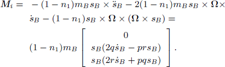
2) Moment equation
In (2), \({I_0}\cdot\dot \Omega + \Omega \times ({I_0}\cdot\Omega )\) is conventional aircraft’smoment. \((1 - {n_1}){m_B}{s_B} \times [{\ddot s_B} + \dot \Omega \times {s_B} + 2\Omega \times {\dot s_B} + \Omega \times (\Omega \times {s_B})]\) is the cargo moving parameter’s effect on moment equation. M 0 is the initial external moment vector in three axes. (−n 1) s B × F is the kinetic moment caused by moving load.
3 The analysis of main impact factor of aircraft characteristic
3.1 Axial motion analysis
According to (1), the total force on the aircraft system is
The first item is caused by external force, the third item is caused by inertia force, and the second item can be rewrite as
Substitute the distance, speed, and angle speed vector of aircraft and cargo into the equation
According to the analysis of (3), the main forces on the three axes are external force, inertia force and the inertia force which is generated by the movement of cargo. The last force is caused by airdrop, and both the cargo’s weight and motion parameter in (5) will affect the aircraft’s flight track.
3.2 Angular motion analysis
3.2.1 Moment analysis
Transform (2) to
Then the right side of (6) is the total moment
Through the analysis of (7), we can divide it to
-
1)
Aero dynamical moment
$${M_a} = {M_0} + ( - {n_1}){s_B} \times F = \left[ {\matrix{{\bar L} \hfill \cr {M + {n_1}{s_B}{F_z}} \hfill \cr {N - {n_1}{s_B}{F_y}} \hfill \cr } } \right].$$ -
2)
Inertial moment
-
3)
Gyro moment
$${M_g} = - \Omega \times ({I_0}\cdot\Omega ) = \left[ {\matrix{{qr({I_z} - {I_y}) - pq{I_{xz}}} \hfill \cr {pr({I_x} - {I_z}) + ({p^2} - {r^2}){I_{xz}}} \hfill \cr {pq({I_y} - {I_x}) + qr{I_{xz}}} \hfill \cr } } \right].$$

So the total moment can be rewritten as M = M a + M i + M g , i.e., aero dynamical moment, inertial moment and gyro moment. The (−n 1) r 1 × F is the main factor that makes the aircraft attitude change.
3.2.2 Moment analysis
According to (6), the rotary inertia is

The cargo moving parameters also will affect the rotary inertia. Through the moment and rotary inertia analysis above, we can say that, the cargo moving will generate additional moment and rotary inertia, and then affect the aircraft attitude.
4 Simulation and discussions
4.1 Angular motion analysis
Take a 100 ton’s transport aircraft with 10 ton’s cargo for example, the aircraft is assumed to fly at medium height and medium speed (H = 1000–2000 m, total V = 300–400 km/h). Substitute the different parameters into the simulation system, the results are presented and compared with experimental data for the detailed flight condition.
4.2 Study of control and stability characteristic
4.2.1 Data analysis of airdrop
The initial position of the 10 ton’s cargo is assumed to be the CG, when the aircraft arrives the airdrop point in different condition, the cargo starts to move at different moving acceleration, and is dropped out at the end of the hold. According to the process described above, we can get the simulation results as follow.
In Table 1, a is the moving acceleration of heavy cargo, α 0 is the aircraft’s trimmed angle of attack (AOA) with cargo in the initial position, α max is the aircraft’smaximum AOA in the airdrop process. Table 1 shows that, the trimmed AOA will increases slightly as the height increases, but the maximum AOA will vary dramatically. And the larger the cargos’ moving speed or acceleration is, the smaller the cargos’ moving time and its effect on vehicle response are. So when we drop the heavy cargo, cargo’s moving acceleration or speed should be chosen properly to make sure that the aircraft’s response does not exceed the bound of aircraft safety, which will guarantee the smooth flight of aircraft by the conventional control.
Except the different airspeed and cargo movement mode, the dynamic characteristic of aircraft during the airdrop also depends on the cargo weight and flight height. According to the results above, we define the airdrop condition is that, flight speed is 324 km/h, and the moving acceleration is −1.5m/s2. The simulation results for different flight height and cargo weight without control strategy are shown below in Table 2.
By combining Tables 1 and 2, it is shown that, as the cargo weight increases, the initial trimmed AOA will increase, the corresponding maximum AOA will also increase.
4.2.2 Simulation analysis of airdrop
With the typical flight condition in Table 3, Figs. 1–4 show the results of simulation compared to experimental data.

Curves of angle of attack

Curves of flight height

Curves of flight speed

Curves of pitch angle rate
These figures above show that the simulation curves based on the model can reflect the tendency which the airdrop process effect on aircraft, and when the 10 ton cargo moves and drops out with the acceleration −1.5 m/s2, a big moment for head-up and AOA will be produced as the CG moving back because of the cargo’s movement. So the height will increase and the airspeed will decrease gradually until the cargo is dropped out. The flight parameter in this process varies dramatically, and the airdrop is unsafe.
4.2.3 Impact analysis of airdrop factor
During the airdrop process, both the movement of aircraft and cargo will impact the airdrop process. When the aircraft’s airspeed is 324 km/h, height is 1000 m, the flight states curves with different airdrop parameters (cargo mass m B , cargo moving velocity v B , initial position d) are shown as follow, are shown as Figs. 5–10.

Flight speed curves of different m B

Angle of attack curves of different m B

Flight speed curves of different v B

Angle of attack curves of different v B

Flight speed curves of different d

Angle of attack curves of different d
When the 10 ton cargo moves back at the acceleration of − 1.5m/s2, and the flight height is 1200 m, we can compare the flight curves at different airspeed as Figs. 11∓12.

Height curves of different flight speed

Angle of attack curves of different flight speed
When the 12 ton cargo moves back at the acceleration of − 1.5m/s2, and the airspeed is 324 km/h, we can compare the flight curves at the different flight height as Figs. 13–14.

Angle of attack curves of different flight height

Airspeed curves of different flight height
According to the simulation curves above, we can conclude that
-
1)
Because of airdrop, the aircraft will climb up and then slows down, the pitch angle and AOA will oscillate during this process.
-
2)
The heavier the cargo’s weight is, the more strenuous the aircraft’s curves oscillate and the larger the peak values of pitch angle and AOA.
-
3)
The larger the cargo’s moving acceleration and speed, the less the cargos’ moving time in the hold, and also the less the effect on the flight condition.
These conclusions also validate the results of aerodynamic characteristic analysis in Section 3.
5 Model simplifications
For successful system modeling, on the one hand, it must be “simple” enough so that it is amenable to mathematical analysis. On the other hand, it must be “complex” enough so that it can be used to faithfully model the complicated and non-trivial behaviors or plant[13, 14]. Based on the system analysis in Section 3, we simulate and evaluate several items’ effect on the system modeling, and then simplify the model in this section.
5.1 Contribution of inertial force
The inertial force which is caused by cargo moving in body frame was analyzed in Section 4.1. As multiplied by the weight ratio n 1 ≪1, cargo movement’s effect on system equations is much smaller than aerodynamical thrust and weight of aircraft.
For evaluating several items’ impact on the system, the initial position of the cargo is assumed to be the CG, and the simulation condition was assumed to be the same as Section 4.2.2.
When the cargo moves back at a = −1.5 m/s2, we can get the AOA curves with the impact of inertial force and without it. Fig. 15 shows that, the simplified model’scurve is the same as the complete model, the simplification did not affect the system seriously, and the inertial force can be neglected during the system analysis.

AOA response for Section 5.1
5.2 Contribution of inertial moment
The moment analysis of Section 4.2.1 during the cargo moving shows that, the total moment is made up of aerodynamic moment, inertial moment and gyro moment. Among these items, the aero dynamic moment and the gyro moment are the same as the items in the conventional aircraft model, and the inertial moment (which contains cargo’s position, speed, etc.) is caused by the cargo’s movement. If the simulation condition is assumed to be also the same as Section4.2.2, we can get the AOA curves with the impact of inertial moment and without it. As the figure is similar to Fig. 15, it was omitted due to space limitation. And the inertial moment can also be neglected during the system analysis.
5.3 Effect of cargo movement on the rotary inertia
From the rotary inertia analysis in Section 4.2.2, we can see that the cargo’s moving also affects the rotary inertia of aircraft. But compared with the aircraft rotary inertia I y and I z , its effect on the system equations is limited. If the simulation condition is assumed to be the same as Section 4.2.2, we would also get the AOA curves with the impact of rotary inertia and without it, and it is similar to Fig.15. Through these analyses above, the inertial force, moment and rotary inertia of cargo moving do not affect the aircraft seriously, and can be neglected.
5.4 Contribution of aerodynamic moment
In Section 4.2.1, (−n 1) r 1 × F is the aerodynamic moment which is caused by system CG variation. In this item, F is the combination of aerodynamic force R Σ and thrust. Because the aero dynamical moment caused by cargo’s moving is as big as the aircraft moment, it is the main cause for transport aircraft attitude variation.
If the simulation condition is assumed to be the same as Section 5.2.2, we can also get the AOA curves with the impact of aerodynamic moment and without it in Fig. 16 above. Fig. 16 shows that, without the impression of aerodynamic, the system response is just the straight line, that means the cargo moving does not affect the flight model when the aerodynamic moment is neglected, that means these simplifications cannot reflect the airdrop process correctly, and the aerodynamic moment of cargo moving has a critical effect on aircraft attitude variation.

AOA response for Section 5.4
6 Conclusions
The characteristic analysis and flight simulation with cargos moving were presented in this paper. The cargo moving parameters had an important effect on the characteristic among several factors. For the aircraft airdropping, if the cargo moves faster, the transport aircraft fly lower and faster, the airdrop process is smoother, and then the flight security can be guaranteed.
Compared with the other items, the aerodynamic moments impact on the system equations is more obvious. So the other items can be neglected in the force equations and moment equations in the range of tolerance error, which can simplify the system model, and reduce the complexity of the control strategy design.
References
S. Dellicker, R. Benney, S. Patel, T. Williams, C. Hewgley, O. Yakimenko, R. Howard, I. Kaminer. Performance, Control, and Simulation of the Affordable Guided Airdrop System, AIAA Technical Report 2000-4309, USA, 2000.
P. A. Cuthbert. A Software Simulation of Cargo Drop Tests, AIAA Technical Report 2003-2132, USA, 2003.
P. A. Cuthbert, K. J. Desabrais. Validation of a Cargo Airdrop Software Simulator, AIAA Technical Report 2003-2133, USA, 2003.
R. Wright, R. Benney, J. McHugh. Precision Airdrop System, AIAA Technical Report 2005-1644, USA, 2005.
K. J. Desabrais. Aerodynamic Forces on an Airdrop Platform, AIAA Technical Report 2005-1634, USA, 2005.
P. Ke, C. X. Yang, X. S. Yang. Extraction phase simulation of cargo airdrop system. Chinese Journal of Aeronautics, vol. 19, no. 4, pp. 315–321, 2006.
P. K. Menon, G. D. Sweriduk, E. J. Ohlmeyer, D. S. Malyevac. Integrated guidance and control of moving-mass actuated kinetic warheads. Journal of Guidance, Control, and Dynamics, vol. 27, no. 1, pp. 118–126, 2004.
B. Bagdonovich, K. J. Desabrais, R. Benney. Overview of the Precision Airdrop Improvement Four-Power Long Term Technology Project, AIAA Technical Report 2003-2102, USA, 2003.
K. Raissi, M. Mani, M. Sabzehparvar, H. Ghaffari. A single heavy load airdrop and its effect on a reversible flight control system. Aircraft Engineering and Aerospace Technology: An International Journal, vol. 80, no. 4, pp. 400–407, 2008.
J. Chen, Z. K. Shi. Aircraft modeling and simulation with cargo moving inside. Chinese Journal of Aeronautics, vol. 22, no. 2, pp. 191–197, 2009.
L. S. Brian, L. L. Frank. Aircraft Control and Simulation, Chichester: John Wiley & Sons, Inc., pp. 54–73, 1992.
J. L. Boiffier. The Dynamics of Flight: The Equations, Chichester: John Wiley & Sons, Inc., pp. 103–120, 1998.
M. Xiao. Modeling and adaptive sliding mode control of the catastrophic course of a high-speed underwater vehicle. International Journal of Automation and Computing, vol. 10, no. 3, pp. 210–216, 2013.
A. Anyakwo, C. Pislaru, A. Ball. A new method for modelling and simulation of the dynamic behaviour of the wheel rail contact. International Journal of Automation and Computing, vol. 9, no. 3, pp. 237–247, 2012.
Author information
Authors and Affiliations
Corresponding author
Additional information
This work was supported by the Fundamental Research Funds for the Central Universities (No.310201401JCQ01010).
Rights and permissions
About this article

Cite this article
Chen, J., Ma, CB. & Song, D. Kinetic Characteristics Analysis of Aircraft During Heavy Cargo Airdrop. Int. J. Autom. Comput. 11, 313–319 (2014). https://doi.org/10.1007/s11633-014-0794-5
Received:
Revised:
Published:
Issue Date:
DOI: https://doi.org/10.1007/s11633-014-0794-5