
Abstract
Difficult-to-cut alloys, which include titanium, cobalt, nickel alloys, and high-strength and heat-resistant steels, can nowadays be manufactured using selective melting (SLM), and products made of such materials are widely used in aerospace, automotive, and medical applications. SLM is widely used among other methods of additive manufacturing (AM) for the production of parts with complex geometry which are difficult to produce using conventional manufacturing processes. In this review article, for the first time, a comprehensive literature review of the most important parameters which influence the SLM manufacturing process of difficult-to-cut alloys is discussed and analysed. Parameters such as composition, grain size, defects, texture, and thermo-mechanical properties and their effect on surface integrity, namely surface topography (machined surface defects, surface roughness, surface texture), microstructural alterations (plastic deformation, grain refinement, and orientation, white layer formation), and mechanical properties (work hardening layer formation and microhardness, residual stress) are discussed. As a result, this review article shows the advantages and disadvantages of using various compositions, classifications, microstructure, defects, and properties of SLM of difficult-to-cut alloys on surface integrity and outlines development prospects, challenges, and future trends.
1 Introduction
In recent years, much attention has been paid to the research and development of difficult-to-cut alloys such as titanium, cobalt, nickel alloys, and high-strength and heat-resistant steels [1]. Products made from such materials are increasingly used in automotive, aerospace, instrumentation, shipbuilding, and medical applications. As a rule, these alloys can maintain their structural integrity (high strength, corrosion resistance, and creep) at elevated temperatures near their melting point [2]. On the one hand, this makes it possible to obtain products with excellent physical and mechanical properties, but on the other hand, it causes certain difficulties when manufacturing products from such materials [3], both traditionally and additively manufactured [4]. The excellent physical and mechanical properties of products obtained by additive manufacturing methods significantly reduce the machinability of such products in subtractive machining methods [5]. At the same time, such alloys have low plasticity at room temperature and are poorly deformed, which introduces challenges when manufacturing such alloys using traditional manufacturing methods (i.e. rolling, forging and drawing) and limits their applications [6]. In contrast to subtractive manufacturing which is based on the removal of material from a solid part, additive manufacturing (AM) processes such as selective laser melting (SLM) use a layer-by-layer method for manufacturing products into their final shape [7, 8, 9]. Other processes include wire and arc additive manufacturing (WAAM) [10], laser powder bed fusion (LPBF) [11], and DED [12]. SLM process employs efficient lasers to create three-dimensional physical objects according to a given configuration using layer-by-layer selective melting [13]. Nowadays, additive manufacturing techniques such as SLM are used to make spare parts as a replacement for welded components in aeronautics [14]. The physical and mechanical properties greatly depend on the material processed which could often exceed those manufactured by traditional technologies. This is because SLM enables the creation of complex geometries and the use of advanced materials that cannot be easily produced with traditional manufacturing techniques; therefore, SLM is actively used where it is most important [15]. The constant development of AM makes it possible to produce geometric shapes of any complexity for a wide range of alloys with excellent mechanical properties and close to 100% density [16]. Many works, including reviews, are devoted to the study of SLM process; however, it is important to identify those related to difficult-to cut alloys. For example, Gong et al. [17] reported on various additive manufacturing (AM) methods including SLM; however, the effect of input parameters of these methods on surface integrity, surface topography, microstructural alterations, and mechanical properties was not reported. Maconachie et al. [18] and Dhiman et al. [19] studied SLM lattice structures establishing a correlation between the mechanical properties and relative density of many topologies elementary cells; most of the material data analysed presented values within the range of values predicted by the Gibson-Ashby model. This model suggests positive power relationships by the relative density and mechanical properties. Typically, SLM products have a porosity of 0–3% [20]. Wettability, surface tension, and melt viscosity play an important role in the process of manufacturing products by the SLM. Also, to obtain a high-quality melt strip, it is necessary to find the optimal process parameters in the corresponding rather narrow range (scanning speed and laser power) [21]. However, the appearance of internal stresses, their presence, and magnitude is associated with the geometric shape of the product, as well as the rate of heating and cooling, with the coefficient of thermal expansion, as well as structural and phase changes in the metal [22]. Perceptible internal stresses can cause deformation and formation of macrocracks and microcracks [23, 24]. The negative impact of the previously listed factors can be partially mitigated by the use of heating elements that can be installed around the substrate or powder feeder and inside the installation. Moreover, another kind of post-treatments can induce compressive residual stresses on the part’s surface, allowing the enhancement of fatigue life [25]. In addition, the optimal orientation of parts in the build chamber reduces the area of fused sections [26], heat treatment to relieve internal stresses [20], and the use of a “staggered” laser scanning strategy [27]. A very important quality indicator of the surface of a part is the state of its surface integrity as a result of modification due to the manufacturing process [4]. There are three aspects of surface integrity [4]: (a) topography characteristics, including machined surface defects, surface roughness and surface texture( b) microstructural alterations, including plastic deformation, grain refinement and orientation, and white layer formation; and (c) mechanical properties, including work hardening layer formation, microhardness, and residual stress. Indeed, SLM is currently a very intensively developing method of AM [28]. However, an analysis of the literature shows that up to date, there are no review articles that could establish a complex relationship between surface integrity on aspects such as surface topography, microstructural changes, and mechanical properties for SLM of difficult-to-cut alloys. The use of these alloys is increasingly significant, and the studies obtained will significantly expand the understanding of the SLM process and show promise for future research.
This review article for the first time presents a comprehensive analysis of the most important parameters in SLM of difficult-to-cut alloys on surface integrity aspects such as surface topography, microstructural changes, and mechanical properties. The structure of the review article consists of an introduction. Section 2 describes selective SLM of titanium, cobalt, nickel alloys, and high-strength steels with their composition, classification, grain size, defects, texture, and properties. Section 3 provides definitions and an understanding of the concept of surface integrity. The structure of difficult-to-cut alloys manufactured via SLM has an impact on surface integrity in a variety of ways, including surface topography, which includes machined surface defects, surface roughness, and texture; microstructural alterations, which include plastic deformation, grain refinement and orientation, and white layer formation; and mechanical properties, which include work hardening layer formation as well as microhardness and residual stress, which are all discussed in Section 4. Section 5 presents challenges and future trends in the development of SLM for difficulty alloys. Section 6 summarizes the conclusions.
2 Selective laser melting of difficult-to-cut alloys: composition, classification, microstructure, defects, and properties
It is possible to melt and fuse metallic powders using SLM process, which is an additive manufacturing technology that uses a high-power density laser to melt and fuse metallic powders [1]. The SLM technique can produce components from a large variety of metals and metal-based composites and offers advantages such as design flexibility and manufacturing cycle time [29]. According to Shen et al. [30], certain planes are more prone to strain during the macroscopic elastic deformation; due to the crystallographic orientation of the material, the SLM developed a high textured microstructure due to the step solidification [31]. Depending on the average plane direction developed in the solidification stage, the plastic deformation can be hindered and increase the difficulty to cut these materials. Figure 1 illustrates the microstructure of difficult-to-cut alloys produced via SLM process. Moreover, examples of commercially available alloys are described in Table 1.

Commonly used difficult-to-cut alloys are presented in Table 1. Two nickel-based alloys, the Inconel 718 and Inconel 625, are widely studied in the literature. Inconel 718, which is niobium-modified precipitation hardening nickel–iron alloy, presents the nominal composition of 50–55 wt% of Ni, 17–21 wt % of Cr, 4.8–5.5 wt% of Nb, 2.8–3 wt% of Mo, 0.65–1.15 wt% of Ti, and 1 wt% of Co, and some other elements might be present as well, such as Al (0.2–0.8 wt%), and Fe (balance) [34]. Inconel 625, on the other hand, is a nickel-based superalloy strengthened with a solid solution. These two superalloys are extensively present in aerospace applications. Moreover, it also appears in pressure vessels and nuclear and chemical applications. The features of Inconel 625 at high temperatures include excellent corrosion resistance and high tensile and fatigue strength; they are particularly well suited for high-temperature and high-pressure applications. The composition of Inconel 625 alloy is 62.10 wt% Ni and 22 wt% Cr matrix with some other elements with 4 wt% of Nb, 9 wt% of Mo, 2.5 wt% of Fe, 0.2 wt% of Mn, and Si [39].
The Fe-based alloys 17-4PH and 15-5PH also appear in the additive manufacturing process. These are martensitic precipitation-hardening stainless steel alloys. Their microstructure can be tailored as a function of the building chamber atmosphere. For instance, manufactured components present austenite (50–75 vol%.) and martensite (25–50%vol.) under a nitrogen atmosphere. On the other hand, components are mainly formed by martensite (92%vol.) under an argon atmosphere [40]. Ti-based alloys are also materials of interest in additive manufacturing due to their high strength-to-weight ratio [40]. Ti–6Al–4 V has a nominal composition of 6.4 wt% of Al, 4 wt % of V, and some trace elements such as Fe and Ta, with Ti (balance). TA32, a near α high-temperature titanium alloy (Ti5Al4Sn2Zr1Mo0.25Si1Nb), has a great interest in aerospace as a material for motor afterburner parts and also as cruise missile parts. Refractory materials, e.g., niobium, tantalum, and tungsten, are mainly used when applications demand extremely high-temperature-resistant materials, e.g., radiatively cooled thrusters. On the other hand, cobalt-based alloys are typically used in applications where temperatures are elevated but lower than in the first case of applications [38], typically up to 800 °C [41].
Even with SLM’s significant advances in additive manufacturing, numerous microstructural faults can severely impact the overall functionality and strength of the created part. Many issues have been studied; however, in this part, the focus is on some of the most popular ones, which will be discussed later in the present work, such as porosities, plastically deformed regions, grain orientation, and white layer formation [42, 43]. The mechanical flaws due to lack of fusion (LOF) and cracking in solidified areas are two of the most often seen problems in SLM of such alloys. In LOF, gas is kept within the structure instead of a sticky solid in a similar situation. Employing an inadequate power laser source or an inadequate scanning speed across a dusty surface can result in insufficient melting of the metal powder and the lack of a strong bonding medium for solidification. Internal stresses caused by a material’s limited heat conductivity and high coefficients of thermal expansion, particularly along grain boundaries where dislocations are present, result in cracking, which is yet another mechanical defect [44, 45]. Some of these defects are shown in Fig. 2.

Defect of keyhole-induced porosity: A Defect of lack of fusion pores and gas-induced porosity. B Scanning speed effect on part porosity: C (I) 250 mm/s, (II) 500 mm/s, (III) 750 mm/s, and (IV) 1000 mm/s. Laser power effect on part porosity: D (I) 90 W, (II) 120 W, and (III) 180 W, adapted from DebRoy et al. [40]
Ran et al. [46] evaluated the morphological and mechanical properties of TA32, presenting microstructural features, such as polished surface characteristics as a function of laser power, and grain refinement as a function of laser power. In both property evaluations, the authors showed that the higher the laser power values, the lower the porosity and building defects are, and the higher the surface quality is. However, the authors observed a keyhole effect, which regenerates some pores after the solidification. Moreover, they addressed the reasons behind the vaporisation of aluminium and other elements. This fact requires tuning the laser power to prevent a lack of fusion and avoid elements vaporisation. The authors suggested that the laser power range should be from 250 to 350 W in this specific case (a machine of Ytterbium fibre laser with a maximum beam spot size of 200 μm). For surface quality, the grain size shows an increasing trend with increasing laser power (see Fig. 3).

Laser power influence on grain sizes morphology of TA-32 alloys: laser power 200 W (a); 250 W (b); 300 W (c); 350 W (d); 400 W (e) [46]
In Fig. 3, the authors varied the laser power for the evaluation of the microstructure chance and also the occurrence of defects. In Fig. 3 a to e, when power input increases from 200 to 400 W, the grain sizes also increase from 12,4 to 62 µm; In Fig. 3a, the occurrence of porosity caused by the leak of fusion due to the low power input (200 W). The mechanical properties of TA32 SLMed parts presented a maximum value for 300W laser power. However, for 250 W, the ductility of the components has shown higher values and similar tensile strength compared to 300 W parts (see Fig. 4).

Laser power influence on the strength (a) and ductility (b) of TA-32 alloys [46]
Considering the mechanical properties, the strength of the SLM processed parts presented a maximum value of 300 W, because of the lower defects density that occurred in such process conditions (cf. Fig. 4). The authors compared other works of literature, which returned to their components’ position. Although one reference showed a Ti-6Al-4 V part presenting 1420 MPa strength in the literature, the exhibited value of 1262 MPa places the work of Ran et al. in the average of the other two works and higher than the other five works (we decided only to cite the main work of Ran et al. [46]). The authors did not fully address the explanation of the values of the SLM part’s strength. However, they stated that the higher the laser power inputs, the bigger the average grain size. These grain size modifications are associated with higher energy input being more beneficial to crystal growth than crystal nucleation. They also inferred that the presence of these defects plays an essential role in mechanical behaviour trends. Although the authors gave no further information about this behaviour, this is because when the grain size of a metal is reduced, the number of grain boundaries — the interfaces between the grains — increases. These boundaries act as barriers to dislocation motion, increasing strength and hardness. Additionally, smaller grain sizes can increase ductility and toughness, as the smaller grains allow for more deformation before fracture. However, there is a limit to how small the grain size can be reduced before other factors, such as impurities or defects, become more influential in determining the mechanical properties. The high-temperature mechanical properties of these parts presented 712 MPa at 600 °C, which the author considered a desirable value. Due to its layer-by-layer build-up, the parts built by the SLM process usually show strong crystallographic texture, which can affect the sample’s mechanical properties and induce anisotropy. This issue can be alleviated by using optimal process parameters [47, 48]. Typical mechanical properties of difficult-to-cut alloys manufactured via SLM are described in Table 2.
The texture of the components is a function of the neighbourhood conditions of the molten pool, component thickness, and microstructure (heat removal direction/ thermal gradient). Unmelted powder particles collocated to the contour pass/molten pool cause randomly oriented crystals/grains due to heterogeneous nucleation. As the component is built in and grows away from these regions, crystal/grain preferentially occurs in direction [001] (see Fig. 5). Figure 5 a shows an example of an α-phase microstructure and a calculated β-grain microstructure in Fig. 5b with equiaxed grain. Due to the predominant heterogeneous nucleation caused by the contact of the molten pool with the surrounding powder bed, the crystallographic orientation of the grains in these areas is primarily random. As the wall thickness increases, cross-hatching requirements increase, and these conditions develop a microstructure composed of long columnar grains (Fig. 5c–e).

Original α-phase map (a) and (b)–(e) rebuilt β-grain structures for 1 mm, 1.5 mm, 2.0 mm, and 5 mm broad walls. The black lines indicate a 15° or more misorientation. The inverse pole figure (IPF) orientation contrast concerns the construction direction NZ [55]
In conclusion, the microstructure, defects, mechanical properties, texture, and surface quality are closely dependent on the primary processing parameters of the PBLF/SLM machine (power beam, energy density, scan speed, powder morphology and moisture, powder layer thickness, among others) and post-treatment processes such as thermal-treatment processes (stress relieve, solid precipitation, artificial aging, hot isostatic pressing, among others) and machining processes (paper-sanding, polishing, among others). Therefore, optimising and adapting these factors to a specific application is highly recommended to optimise and adjust these factors to a particular application. Due to the wide availability of powder alloys for SLM with the combination of post-processing treatments and its capability to produce components with similar mechanical strength and fatigue life in comparison to traditionally manufactured components parts, SLM is a promising technique for parts made with high format complexity and suitable for the aerospace and the nuclear sectors.
3 Surface integrity of difficult-to-cut alloys manufactured via SLM process
Astakhov [56] defined surface integrity “as a set of various properties (both superficial and in-depth) of an engineering surface that affect its performance during service.” This definition showed the concerns with the functionality of surfaces instead of a simple result of a specific manufacturing process. In order to focus on mechanical components, two aspects of surface integrity — geometrical and physical — deserve special attention. The surface roughness should be described to represent the geometrical aspect. Otherwise, the residual stresses are a relevant topic to consider in terms of physical meaning. Although the average surface roughness is a robust indicator of manufacturing variability, i.e., it is also useful as a quality control indicative since it has a considerable effect on part integrity. Astakhov [56] cited nine metal cutting processes and eight abrasive processes to describe the ranges of Ra values. Ra reported from all cutting processes ranged from 0.8 to 6.3 µm, and from 0.1–0.8 µm in abrasive processes. Consequently, talking about surface functionality is much less probable using only Ra or another average parameter. Each surface has a distribution of heights, determined by peaks and valleys. The height distribution should be treated as a statistical function. The most well-known curve representing the height distribution is Abbott-Firestone [57]. Some standards are available to determine roughness parameters from the Abbott-Firestone curve, notably ISO 13565 series regarding 2D parameters and ISO 25178 on areal surface texture (3D) [58]. The calculation using bearing curves includes non-trivial mathematical manipulations of graphs. Franco and Sinatora [59] showed that standard instructions do not result in values that might be considered “average heights.” For this reason, we prefer to describe the distribution in Gaussian or non-Gaussian through the Ssk-Sku map [60]. Figure 6 shows results obtained by Mehl et al. [61] for CNC-machined, electro-machined, and electro-polished Ti-alloys for implants and abutments. Together with their points, other literature results are presented, helping to visualise that the Gaussian surfaces can be obtained from entirely different processes in terms of average roughness — shot-peening or polishing.

Lou et al. [62] described all topographical issues of SLM surfaces as a function of different product mechanisms. Besides roughness, waviness, and form error, they included the presence of globules and surface pores as surface components. These aspects imply creating new methodologies to describe the topography. Therefore, these authors proposed to extract globules/surface pores using watershed segmentation. The extraction of waviness was also studied, using two alternatives: (i) a robust Gaussian regression filter and (ii) morphological opening filter. In Fig. 1, one can observe the value of Ssk/Sku for studied cases presented in [62]. A non-Gaussian surface has resulted from the SLM process, differing from conventional mechanical modifications/treatments. The waviness extraction method has a significant effect on the values. When the Gaussian regression filter was applied, the SSk-Sku values were closer than the Gaussian height distribution.
Residual stresses can be a result of thermo-mechanical effects during processing. Depending on the applied process, more significant differences in mechanical properties can be predicted and determined at different regions formed, implying residual stresses [63, 64]. Parrish [65] classified three types of residual stress distribution for machining processes. The heat generated by friction or other source is responsible for superficial tensile stresses (type I). At the same time, the hardening due to the plastic deformation causes compressive stresses at the surface (type III). An intermediate case is a combination of plastic deformation and heat generation, where a peak of tensile ones follows the compressive stresses at the surface. During SLM processes, heat generation turns the control of residual stresses into a relevant challenge. Different simulations have been applied to surpass this difficulty [66, 67]. Carraturo et al. [68] applied immersed boundary methods to predict the residual stresses of the 10-layer SLM structure. They verified an unlikely distribution of stresses compared to those classified in reference [65]. In this case, longitudinal and transversal stresses are initially in tension, then in compression, and almost vanish at the bottom of the base plate. An explanation for this behaviour was given by Ming et al. [69]. which is associated with the differences in cooling rates observed in surface and subsurface regions of a material processed by SLM. Besides, the differences in cooling rates considering directions result in anisotropy of residual stresses. Figure 7 presents the profile residual stresses for all types described here: three based on conventional machining and one (type four) based on the investigation performed in [66].

Residual stress distributions: types I, II, and III due to conventional machining [65] and type IV resulted from SLM
In subtractive manufacturing processes, it is possible to analyse surface integrity by considering the topography and residual stresses simultaneously. For example, Morelo et al. [70] showed for bored super-duplex stainless steel that the use of the Sq parameter was pretty correlated with the compressive or tensile stresses values determined at the surface: the higher the Sq value, the higher the tensile residual stresses. On the other hand, this task sounds distant in additive manufacturing. Yang et al. [71] described several methods to characterise metal additive manufacturing processes and products. They infer a relatively lower surface roughness and relatively higher residual stresses for power bed processes, including SLM. Even though this description would refer to other AM processes, for powder injection, the relation between roughness and stress is also the opposite: a higher surface roughness would be accompanied by lower stresses. The indicative made by Yang et al. [71] can be discussed in terms of the uncertainty of roughness determination for SLM parts. Thompson et al. [72] measured the topography of an SLM Ti-6Al-4 V part using four commercial instruments. The discrepancy reached 61.9% in the reconstructed profiles. The main relationship between the microstructure of additively manufactured parts and subtractive machining processes is a crucial factor that affects the final surface texture of the part. The interaction between the crystallographic and grain morphology (size, shape, orientation) of the additively manufactured and the characteristics of the machining process such as the cutting tool geometry and tool position is known to influence the developed cutting forces [73]. Therefore, there is an immense challenge in determining the topography of additively manufactured components. Until a new paradigm could be established, the surface integrity understanding will remain open, and the relativisation of surface characterisation will be a mere speculation.
4 Influence of SLM structure of difficult-to-cut alloys on surface integrity
4.1 Influence of surface topography of difficult-to-cut alloys manufactured via SLM process
4.1.1 Influence of surface defects
A major disadvantage of SLM process is the excessive formation of defects, which can be mitigated as discussed in this section. The surface and bulk quality of SLM parts depend mainly on powder thickness, SLM environment, and parameters like laser energy, the thickness of SLM layers, scan speeds, and hatch spacing. Improper choice of any one or more parameters could be the reason for defect formation in SLM parts. These surface defects can drastically decrease the overall strength and performance of SLM part, by forming a point of stress concentration and initiating and propagating the fatigue cracks [74]. These cracks should be eliminated, or their size should be reduced till their effect is negligible [75]. This section mainly focuses on the surface defects of SLM parts, their types, and measures to eliminate or reduce them.
Surface defects are an essential parameter to look out for while defining the surface integrity and quality of a part produced by a machining operation. The surface defects in SLM-produced parts are mainly of three types: incomplete fusion holes or lack of fusion (LOF), cracks, and porosities. Incomplete fusion holes or lack of fusion are the defects mainly produced by low-energy inputs. Other factors can contribute to the formation of these defects, such as lower laser power, fast scanning speed, and large hatch spacing. Due to this, the metal powder particles are not appropriately melted, and the next new layer is not deposited correctly on the last layer, with an adequate overlap [76, 77, 78]. Incomplete fusion hole defects consist of unmelted metal powder, which is not easily melted during the deposition of the next layer, as shown in Fig. 8.

LOF defect in SLM manufactured Ti-6Al-4 V alloy: a along layer boundary; b un-melted powder particle [75]
These imperfections cause the part’s surface to be rough, which results in an improper flowing of liquid metal, resulting in interlayer faults, which also have the potential to proliferate, resulting in enormous multilayer faults [79]. Liu et al. studied the consequences of manufacturing flaws in Ti-6Al-4 V alloys treated through selective laser melting. The outcomes show that the LOF defect increases local stress, hence beginning a fatigue fracture and lowering the material’s strength. Additionally, the flaw’s position is also critical in determining its effect. A LOF fault at the material’s free surface resulted in a reduced fatigue life [75]. Masuo H. et al. conducted studies to determine the effect of hot isostatic processing (HIP) on Ti-6Al-4 V alloys generated using SLM. They determined that the majority of flaws created were LOF defects and that the majority of these defects could be removed using the HIP approach [80].
Another surface defect in SLM parts is the formation of cracks (generally hot cracks), which are formed by the high stability of liquid metal at low temperatures [81]. These are the results of very high cooling rates followed by high local power laser interaction with the metal powder. Cooling rates of the order of 108 K/s cause increased residual stresses and thermal gradients, resulting in cracks formation in the SLM part (Fig. 9) [82, 83, 84]. According to research performed by Mercelis et al. [85] highly dense parts produced by the SLM, the method was subjected to more stresses. Kempen et al. conducted experiments to make a highly dense M2-HSS without significant component cracks [86]. The authors pre-heated the base plate and observed several outcomes to achieve this. Firstly, the pre-heating resulted in lower thermal gradients. Additionally, they found that a higher pre-heating temperature of 200 °C led to less formation of cracks. The study also revealed that using laser surface re-melting (LSR) caused the density to increase but also increased the formation of cracks in parts. This was due to LSR resulting in higher cooling rates and enhancing the formation of brittle martensitic phase, which further increased crack formation.

SEM images of crack initiation in SLM manufactured Ti6Al4V alloy: a crack morphology; b microstructure of sides of crack [82]
Defects in the form of near-spherical shapes are often caused by a low packing density of metal powders during the selective laser melting (SLM) process. When the metal powder is melted, any gases trapped inside cannot escape the final SLM product due to the process’s short solidification time and high cooling rate. As a result, these trapped gases create small voids known as porosities (see Fig. 10). Porosities can also appear near the surface of a hollow structure due to the high temperatures of the liquid metal pool, which increase the solubility of gas and, in turn, cause more significant gas enrichment within the liquid metal pool. This increased gas content leads to the further formation of porosities. Additionally, Qiu et al. found that incomplete re-melting of previous layers can result in ridges within the part [88].

Spherical porosities observed using light optical microscopy by Thijs et al. [87]
Factors affecting the formation of defects
The principle of selective melting of metal powder in SLM manufacturing puts forward three major factors which influence the formation of defects. These three factors are described in Table 3.
While inappropriate selection of any one or a combination of machining parameter, scanning strategy, and powder type can result in defects in SLM manufactured parts, the types, and causes of which has been discussed in this sub-section, various factors are also efficient in decreasing, or eliminating these defects. Increasing the scanning speed and/or input laser power, as discussed above, results in an increase in defects in SLM parts. Consequently, reducing both scanning speeds and laser energy input might prove to be beneficial in reducing the defects within SLM parts. Furthermore, using fine powder metal-particles and using a cross-hatching scanning strategy also results in a reduction of SLM defects.
4.1.2 Effect of SLM parameters on surface roughness
Another main problem or drawback regarding SLM manufactured parts is surface roughness. Frequently surface roughness is even more detrimental than the common defects of additively manufactured materials [80]. In the work of Yasa et al. [96], the surface finishing of parts produced through selective laser melting (SLM) was compared with that of other machining processes and precision forging. The authors found that the SLM parts had higher surface roughness and oxidation levels than the other methods, with roughness levels ranging between 10 and 15 µm. MicroSLM, a type of SLM that uses a smaller laser spot size and finer powder particles, can potentially mitigate the surface roughness and oxidation issues identified by Yasa et al. [96]. Using smaller laser spot sizes, microSLM can produce parts with finer details and smoother surfaces, resulting in lower surface roughness [97]. Also, microSLM can use finer powder particles, reducing the amount of residual stress and defects in the part, leading to lower oxidation levels.
Table 4 provides an overview of the average surface roughness of various materials when processed using SLM, while Fig. 11 shows the surface morphology of SLM-produced parts from two different perspectives.

Although the roughness depends on the temperature of SLM part surface and process parameters like scanning speeds [50], Kaynak and Tascioglu [107] confirmed that a lower surface finish is obtained in the SLM process, also because of various other reasons partially melted powders, and defects like pores and cavities on surfaces of SLM parts. However, the surface roughness also depends on other parameters and factors. Metallic powder size, thickness of layers, liquid metal pool size, and wall angle are more significant than others [108]. Where wall angle or draft angle is of specific surface from the horizontal. Another effect that is also responsible for surface roughness is the staircase effect, which is generated from a combination of thickness of layers and wall angle (Fig. 12). Decreasing the wall angles and increasing the thickness of layers enhances the staircase influence and thus increases the surface roughness. However, increasing the wall angles and decreasing the thickness of layers enhance the stairs’ number but decrease their size, thereby reducing the surface roughness [36].

Influence of wall angle on surface roughness [109]
Mumtaz and Hopkinson [103] studied the top and side surface roughness of SLM-processed Inconel 625. They found that the process parameters that reduced side surface roughness (decreasing repetition, decreasing overlap and increased scan speeds) tend to increase top surface roughness, whereas the parameters which reduced top surface roughness (increasing repetition, increase overlap and reduced scan speeds) tend to increase side surface roughness. However, the use of higher peak power reduces both side and top surface roughness, by improving wettability and smoothening of melt pool surface. Zeng et al. [110] evaluated surface roughness by multi-scale evaluation using length scale tilings. Surface roughness improved when the relative length at scale was comparable to or more than the layer thickness of the SLM process. Numerous different procedures and techniques have been demonstrated to be effective in lowering the roughness and improving the surface quality of SLM components. Laser re-melting or LSR is one such technique that involves melting the surface (of a finished part produced by SLM) till the temperature at which the material melts but less than the temperature of evaporation and allowing it to cool down rapidly (Fig. 13). The cycle of re-heating and rapid cooling is repeated until the desired properties of the material are obtained [109, 111].

Laser surface re-melting (LSR) on a part produced by SLM [109]
Alrbaey et al. [111] concluded that LSR has a great scope of improving the quality of the surface of parts produced from this technology, and can improve surface quality up to 80% [112]. The outcomes of post-processing treatments on surface characteristics on SLM-processed Inconel 718 were studied by Kaynak and Tascioglu [107]. They used 3 techniques, viz. finish machining (FM), drag finishing (DF), and vibratory surface finish (VSF), as illustrated in Fig. 14. The conclusions were as follows:
-
FM operation decreased surface roughness by 96%.
-
DF — 2 h of operation decreased roughness by 73%.
-
DF — 4 h of operation decreased roughness by 88%.
-
VSF operation decreased roughness by 82.8%.

Post-processing techniques to improve surface quality [113]
Surface roughness is a major problem in the SLM process, which shall be reduced to the industry standard of at most 0.8 µm. The high surface roughness of SLM manufactured parts, however, also finds its applications in medical fields for good biological properties, where Ti6Al4V implants manufactured by SLM technique can induce the growth of bones [114]. Surface roughness, as discussed in this section, can be the sole reason for a part to fail. This, sometimes, makes surface roughness even more problematic than surface defects. Considering SLM process, surface roughness has always been a disadvantage, also due to the requirement of post-processing techniques. Further, apart from post-processing techniques to improve surface roughness — like laser surface re-melting (LSR), FM, DM, and VSF — increasing wall angle and decreasing layer thickness produce more, but smaller stairs (stair-case effect), resulting in reduced surface roughness in SLM manufactured parts.
4.1.3 Effect of SLM parameters on surface texture
Surface variations from a completely flat surface are known as surface texture. The surface texture is measured in terms of roughness, waviness and form [115]. Considering the SLM process, various factors like the type of the finishing machining process and parameters, used determine and are responsible for the formation of textures on the finished part. Dursun et al. [116] studied the surface properties of SS316L fabricated using SLM, focusing on the influence of laser input factors on the surface texture. By varying the power-scanning speed inputs, they observed different surface textures. The results showed that increasing the energy density and decreasing the scanning speed during SLM processing led to smoother and better-textured surfaces with improved surface characteristics of the SS316L part. As illustrated in Fig. 15a, keeping the scanning speed constant and increasing laser intensity from 50 to 100 W improved the surface texture considerably. Consequently, the surface texture in Fig. 14c at 100 W is smoother followed by Fig. 14b at 75 W and then Fig. 14a at 50 W. A similar (but inversed) trend was observed when scanning speed was varied keeping the laser power constant, wherein, as also illustrated in Fig. 15b, increasing scanning speed from 200 mm/s (Fig. 15a) to 600 mm/s (Fig. 15c) degrades the surface texture of the SLMed part.

For examining the effects of three different scanning strategies, Valente et al. [117] used island scanning (modelled), island scanning (stripes), and line scan on surface textures of Ti-6Al-4 V alloy produced from SLM technique. Line scanning strategy resulted in the least surface roughness but randomly distributed surface texture, however, more surface roughness and even distribution of textures were observed in island scanning. Covarrubias and Eshraghi studied the relationship between the build angle/slopping angle (α) with the surface properties of SLM fabricated Inconel-718 based on an equation given by Campbell et al. [118].
where Lt represents the thickness of the layer and Ra represents average surface roughness. They varied α from 0 to 90° in intervals of 15° as shown in Fig. 16. The results showed direct dependence of Ra on build angle (α) as per Eq. 1, but only for build angles between 15 and 75°, after which the surface was developed by different mechanisms (Fig. 17) [119]. Moreover, the authors also concluded the presence of higher average roughness along the downskin surface in comparison with the upskin surface. This phenomenon was attributed to partially melted particles of metal powder stuck along the downside surface.

Illustrations showing a SLM cubic test samples studied by Covarrubias and Eshraghi [119], b comparison of experimental and theoretical (dashed lines) results with different build angles for upskin surfaces, and c comparison of experimental and theoretical (dashed lines) results with different build angles for downskin surfaces [119]

SEM images (a–d) and optical surface contours (e–h) comparing the upskin and downskin surfaces at angles 60 and 75° [119]
Yasa and Kruth improved the surface texture and microstructure by re-melting each layer of 316L stainless steel while using SLM process for fabrication [120], whereas Yadroitsev et al. [121] analysed the effects of preheating temperatures and laser speed (keeping other parameters constant) of the same material manufactured by SLM. Both preheating temperature and laser speed influenced the morphology and microstructure of SLM part significantly. In the study of Zhou et al. [122], patterns were created in CoCrMo alloy from SLM, with altering hatch space and scan techniques while maintaining constant laser energy, speed, time of exposure, and point distance. The outcomes suggested a reduced hatch spacing, in conjunction with a cross-hatching technique (Fig. 18), as seen in “Run 3” in Table 5, enhanced the surface quality by forming “W” shaped surface textures.

Different hatching/scanning strategies: a zigzag scanning strategy and b cross hatching strategy with 67° rotation [122]
Jadhav et al. [123] analysed the crystallographic texture of pure copper fabricated via SLM. Relatively random orientation of crystals in XY mid plane and YZ plane was obtained. However, a strong crystallographic texture was seen on the XY top surface. Popovich et al. prepared Cu-Cr-Zr-Ti alloy samples by selective laser melting process to study their microstructures at room and elevated temperatures. Grains of as-built SLM specimens were found to be elongated and along the build direction, with a size of 30–250 µm. However, the application of aging and solution annealing resulted in the elongation of the grains [124].
Surface texture is another key indicator of the overall performance of SLM process. Defined by roughness, waviness, and form, increasing the laser energy density and decreasing scanning speeds have been efficient to improve the surface texture. The relationship between the scanning speed and fabrication time is inversely proportional. However, increasing the scanning speed beyond certain levels would result in reduced size, wettability and flow of the molten pool [125], which creates discontinuous melting tracks and reduced part integrity (defects and reduced hardness) [126]. Therefore, increasing the scanning speed will depend on establishing a stable melt pool using optimum laser power. An alternative to increasing the scanning speed for increased productivity is to employ multiple lasers which dramatically speed up long-running builds, nowadays reported to have machines equipped with up to 12 lasers. However, this will be at the expense of increased laser power requirements, possibly causing increased residual stresses and related defects, and unusual melting pool boundaries but with a significantly reduced build time. The relationship between scanning speed and fabrication time is a complex issue that is governed by many build parameters that interactively affect the part quality and its surface finish. Moreover, using cross-hatching, and island scanning strategies during the manufacturing of SLM parts also improves the surface quality. Various defects in a part produced by the SLM process make inevitable surface irregularities, reduced surface morphology, and reduced fatigue strength of the material. The key parameters which decide the overall performance of the SLM process (powder thickness, powder material, SLM environment, scanning strategy and finish machining parameters) need to be optimised considering different materials, for the best results. Figure 19 illustrates the key topographical features typically observed in parts produced through the SLM process. The figure also provides recommendations for addressing these characteristics.

Topographical features related to SLM-produced parts and recommendations for addressing them
4.2 Influence of microstructural alterations in difficult-to-cut alloys manufactured via SLM process
This section shows how microstructural alterations in the difficult alloy powders affect certain aspects of the products, such as porosity, mechanical properties, grain refinement and orientation, and white layer formation.
4.2.1 Influence of porosity and inclusions
Porosity, defined as the presence of voids on SLM-produced materials, is a common defect associated with this production technique. This defect can occur for two main reasons, according to [76]. Because the powder bed contains approximately 50% porous material, gases contained within the powder may dissolve into the melting pool and become trapped there after solidification as a result of the rapid cooling rate. This problem can be addressed by increasing the apparent density of the powder bed by increasing the coordination number of the powder bed particles [76]. Another reason is the high temperatures generated by the laser beam raising the solubility of gases in liquid metal, making its enrichment easier, which can be solved by diminishing the liquid metal volume, thus lowering the thickness of the layers or reducing the gas pressure in the building. Figure 20 shows porosity due to entrapped gases in Ti-6Al–4 V alloys.

Optical micrograph illustrating porosity and lack of fusion defects on Ti-6Al-4 V alloy [76]
Uncontrolled porosity is generally undesirable because of its detrimental effects on materials’ mechanical properties and is a common issue in the SLM process. Because of that, several studies have been issued addressing the topic of densification of SLM-produced parts. Li et al. analysed the densification of 316L stainless steel powders and found that processing parameters affect pore formation [84]. The scan speed significantly affects pore formations with slower speeds producing samples with less porosity and pieces with higher scan speeds showing more and larger pores due to weaker powder bonding. Another factor that influences pore formation is hatch distance. The bigger the hatch distance, the more significant the probability of voids formation and the appearance of large pores. Laser power also affects porosity, as a piece produced with a 98-W laser showed lower porosity and a smoother surface.
In contrast, many agglomerates were formed in pieces made with an 80-W laser, and a lower flowability favoured pore formation. Koutiri et al. also evaluated hatching parameters, especially values of volume energy density (VED) and building angle, and their effects on the densification process into SLM-produced parts using Inconel 625 powder [50]. The results of the porosities test are shown in Table 5.
This study found that the porosity rates decreased with higher VED values and presented a threshold of 7 J/mm3 for it to happen. This observation occurred because the higher VED values promote larger melting pools, which are more susceptible to re-melt previously deposited material, preventing interlayer porosity. The building angle also affected the densification of the parts, where the higher the building inclination, the higher the heat concentration, increasing the average temperatures and reducing the porosity rate. The study concluded that VED values could be a reliable process parameter alongside scan speed, beam diameter, and laser power.
This subsection discussed reasons for the emergence of porosity in SLM-produced parts and some research experiments that analysed how process parameters such as scan speed and hatch distance affect its severity. These researches on reducing and eliminating porosity on SLM-produced parts are relevant due to the generally negative effects of this phenomenon on the component's mechanical properties.
4.2.2 Influence of plastic deformations
Titanium alloy pieces produced by the SLM process usually show better mechanical properties than conventionally produced parts. As shown by Attar et al. in their paper, the authors produced high-strength commercially pure titanium parts through SLM with superior properties than those conventionally processed due to the formation of martensitic α′ grains and grain refinement [127]. Additionally, the conventional fabrication of complex-shaped parts is complex due to the low machinability and the low ductility of these alloys [128]. Regarding the Ti6Al4V alloy, one of its major applications is in the aerospace industry, and in such cases, the manufactured parts are subjected to complex and multiaxial loads. Sun et al. evaluated the mechanical properties of SLM-produced parts Ti6Al4V alloy given the building direction of samples. The samples produced for tensile testing were different only in the building direction, with other SLM parameters and post-process treatment remaining fixed. Three different build directions were tested: 0°, where the load direction is parallel to the build direction; 45°, where there is a 45° angle between the build and load direction; and 90°, where the applied loads are perpendicular to the build direction. Figure 21a shows the geometry and build direction of the samples. The samples’ tensile properties were obtained through a tensile test, and the results are shown in Fig. 21b and Table 6.

This assessment showed that the building direction impacts the tensile strength and ductility of the samples, with the 0° sample having the worst performance in the study. Although, in this case, where samples built with 0° showed the worst properties, in other studies, the authors presented mechanical properties varying with a broader range of values, such as in the works of [130] and [131]. This range of values can occur due to the effects of build direction being susceptible to the SLM parameters variation, e.g., laser power and hatch spacing, which affect the microstructure of the samples and the pore formation [129]. Another alloy frequently used in SLM processes is the nickel-based Inconel 625. This alloy is also heavily used in aerospace applications. However, the pieces present undesired and anisotropic microstructures due to SLM characteristics, such as columnar grains. Chen et al. evaluated how the post-process treatments can affect the mechanical properties in SLM-produced samples of Inconel 625. [132] evaluated three different samples: as-produced samples, denominated AB, which went through solution treatment at 1070 °C for 1 h and water quenching; the second group, denominated HT, was aged at 720 °C for 18 h; and the last group, denominated HT + LSP, was subjected to laser shock peening after the heat treatment (HT) (aging). Figure 22 shows the tensile test results, and Table 7 shows the tensile properties of the samples.

a Engineering strain–stress curves and b close-up of ultimate tensile strength [132]
The tensile test results show that the HT + LSP performs better than the AB and HT samples. The LSP introduced surface compressive stresses, and heat treatments promoted the dissolution and the transformation of non-desired microstructures, such as dendritic morphology, causing the higher strength values of HT + LSP samples.
These articles show how many variables must be evaluated due to their effect on the end-product mechanical properties. From build direction and process parameters to post-process treatments, every decision made has an impact on the final product and needs to be carefully researched and applied to produce components with the desired properties.
4.2.3 Influence of grain refinement and orientation
High thermal gradients and high cooling rates are characteristics of the SLM process; these factors can produce very small subgrain structures but also can lead to parts with non-equilibrium and textured microstructures. Defects such as porosity, entrapped gas, lack of fusion, and residual stresses are also presented in these SLMed parts [76, 133]. To prevent the previously cited issues, modifying the alloys powders’ microstructures via heat treatments (HT) can produce parts suitable for industrial applications with better mechanical properties. Ghlebus et al. evaluated the influence of material characteristics and processing conditions of Inconel 718 alloys processed via SLM regarding its effects on microstructure and mechanical properties [133]. This study produced four samples of HT variations to analyse the microstructure results. The heat treatment variations are shown in Table 8.
The as-built samples showed laminar structure, cellular dendritic grain structure, and unidirectional columnar structure. The formation of these geometries is determined by building parameters, such as hatch spacing, scan pattern, and layer thickness as shown in Fig. 23.

Microstructure of the as-built samples showing dendritic-cellular grain structure. a Optical microscope image; b SEM image [133]
Individual columns are formed by grains of solid solution γ that have grown in length along the direction of their development. This form of microstructure is caused by epitaxial, dendritic grain development in the direction dictated by heat flow, as well as the desired crystallographic orientation < 001 > , which are both present in the crystal [133]. The microstructure of these samples was not homogenous, with the presence of Laves phase (in the interdendritic spaces and the regions of layer interfaces) and secondary precipitates of γ′/γ″ occurring in the interdendritic spaces and the regions of layer interfaces (in regions with high Nb concentration). The as-built samples underwent a post-process aging treatment, maintaining the pieces’ columnar nature and layered aspect. The results of the experiment are shown in Fig. 24.

Microstructure of the aged samples. a xz plane; b xy plane [133]
Intense etching of interdendritic areas and columnar grain boundaries marked the nonuniform precipitation of γ′/γ″-phase. In addition, the development of needle-like δ-Ni3Nb precipitates in interdendritic spaces. Variant II and III annealing parameters were insufficient for full homogenisation of the γ-phases. Still, the slow heating followed by soaking of the samples caused the dissolution of metastable Laves particles and reduced segregation of Nb particles. Annealing conditions of the variant IV samples caused the homogenisation of γ-phases. The microstructure found in these samples results from grain boundary migration induced by reducing grain boundary area [133]. Also, the γ′/γ″ precipitation and Laves phases were dispersed in the grain boundary on these samples. Vilaro et al. evaluated the microstructure of heat-treated and as-fabricated samples of Ti-6Al-4 V titanium alloys produced by the SLM process [76]. The as-fabricated samples showed a metastable martensite α′ phase that resulted from the rapid quenching from the β domain. This metastable microstructure was also found in as-fabricated samples of other studies [134, 135]. Samples were subjected to annealing heat treatment at 730 °C for 2 h. The result of this experiment is shown in Fig. 25.

SEM image of the sample after annealing at 1003 K (730 C) with 2 h of dwelling time [76]
The previously cited heat treatment strategy caused partial decomposition of the metastable martensitic α′-phase found in the as-fabricated samples into the more stable phase α + β. Vanadium acts as β-phase stabiliser because the vanadium atoms diffuse preferentially in β-phase. The last strategy attempted by Vilaro et al. was a solution treatment followed by a tempering treatment [76]. The solution treatment was carried out at approximately 1050 °C for 1 h and was followed by water quenching. The solution treatment at this temperature causes shearing of the long columnar grains found on the SLM-produced parts and dissolution of the α′ phase into the β-phase. The water quenching in these samples transforms the body-centred β-phase into a hexagonal α′ phase, and as a result, it develops equiaxial grains with approximately 200 μm in diameter. The tempering treatments were carried out at temperatures between 700 and 950 °C for 2 h. In all conditions, one sample was cooled in air, and another sample was cooled within the furnace. Figure 26 shows the microstructure of samples subjected to 850 °C and 950 °C tempering.

SEM images of the microstructures of the samples. a 850 °C tempering treatment and b 950 °C tempering [76]
The authors stated that tempering between 700 and 750 °C causes the formation of α′ + βm + α phases. Between 750 and 850 °C, it forms a soft orthorhombic α″-phase that causes a critical hardness loss. Above 850 °C, it forms the α′ + βr + α phases increasing the hardness of the samples sharply. The cooling rates between air and furnace cooling did not affect the microstructure of the samples in these experiments. The results show that it is possible to produce more desirable microstructures through process optimisation.
The modification of microstructure in SLM-produced components was addressed in this subsection. Previous studies have shown that it is possible to use heat treatments to change microstructural characteristics in parts produced with SLM process. However, it is necessary to suppress and control intrinsic SLM manufacturing defects to make pieces comparable to conventional process routes.
4.2.4 Influence of white layer formation
White layers are commonly associated with the machining processes of Fe-based components, but other alloys also present white layer formation, e.g., Ti-alloys [136] and Ni-alloys [137]. They are called so due to their white appearance on the surface of materials in etched micrographs. These layers usually have higher hardness and lower ductility than the remaining material and, because of that, can be responsible for higher crack formation and lower fatigue resistance in dynamically loaded components [138]. The appearance of white layers is a thermally activated process, and its characteristics in machining are determined by thermal alteration and the chemical composition of the materials [139]. Structural alterations related to white layers can be dynamic recrystallisation, phase transformations, and grain refinement due to severe plastic deformation [138]. The formation of a hardened layer on the surface of components can be a desirable characteristic. It can improve surface finishing, offer higher dimensional precision, and overcome detrimental defects of communication pores [140]. Laser treatments can be applied to some materials to provide hardened layers on the surfaces of components because of heat gradients and self-quenching of the process [141]. However, in the SLM process, due to the temperature gradient and solidification-induced thermal stresses, there can be defects such as porosity, lack of fusion, cracks, and the formation of a white layer on the surface of pieces [136]. The microstructure of the white layer regions is composed of vicinities with chemical composition gradients caused by the diffusion process, which is thermally activated during the SLM process. In the study of Xu et al. with Ti-6Al-4 V samples, there was an evident white layer around the lack of fusion (LOF) defects, as shown in Fig. 27 [136].

White layer around LOF defects on Ti-6Al-4 V sample [136]
The white layer is around the LOF defects with an increase of α phase. The average of four microhardness measurements in the α phase white layer was 885 MPa, higher than the average of six measures of the matrix material, which was 562 MPa. The LOF defect alongside the hard and brittle α phase white layer can lead to crack formation and propagation on the samples. [136]. An Inconel 718/WC composite made with the SLM process found layers on the interface between the WC particles and the Inconel 718 matrix, as shown in Fig. 28 [137].

FE-SEM image showing cases of no gradient interface and diffusion layers at different laser scanning speeds. a v = 650 mm/s; b v = 550 mm/s; c v = 450 mm/s; d v = 350 mm/s [137]
At 650 mm/s laser scanning speed, there is a thin white layer with almost no gradient interface. Reducing scanning speeds caused the thickening of the gradient interface and the emergence of a diffusion layer. The diffusion layer merged with the gradient layer at the lowest speed, forming a coarse and thick interface between the materials. Microhardness values present a trend that the lower the scanning speeds, the higher the microhardness (the highest values were 393.2 HV0.1 for the samples made at 450 mm/s). The 350-mm/s samples presented microhardness values of o 381.6 HV0.1. The authors stated that the coarse microstructure is thought to have reduced the microhardness of the samples [137]. The defects (pores and inclusions), the plastic deformation, the grain size and its orientation, and the white layer formation are strongly dependent on the primary processing parameters of the PBLF/SLM machine and, therefore, care must be given so that requirements of the application are satisfied according to the development of the better condition/development of these factors.
This section addressed the white layer formation in SLM-produced parts. Due to its association with higher crack formation and lower fatigue resistance, the optimisation of process parameters needs to be applied to avoid the appearance of this phenomenon.
4.3 Influence of residual stress in difficult-to-cut alloys manufactured via SLM process
The rapid changes from a solid phase to a liquid phase and again to a solid phase give rise to high thermal stresses in parts manufactured by SLM process [142]. Selective laser melting is generally associated with large temperature gradients, which generates an elastic deformation mismatch. These temperature gradients are generated by repeated cycles of increasing and decreasing temperatures of consecutive powder layers, within a short amount of time [143]. The temperature gradient gives rise to increased residual stresses in an AMed metal structure [144], resulting in the separation of the base plate, cracks, and warpages [87, 145]. The separation of the base plate and cracks is shown in Fig. 29a. Lower solidification time of the melt pool causes the formation of martensitic microstructure, in Ti6Al4V alloy, often with decreased ductility as compared with its hot working equivalent [144]. Lu et al. [146] investigated the residual stresses of Inconel-718 alloys manufactured by selective laser melting process with differing island scanning strategies, where island sizes were taken as 2 × 2 mm2, 3 × 3 mm2, 5 × 5 mm2, and 7 × 7 mm2 (Fig. 29b). The lowest residual stress was found in the specimen manufactured with the size of an island of 2 × 2 mm2, while the highest residual stress was observed in the specimen manufactured with the size of an island of 3 × 3 mm2. The study concluded that the higher the rate of cooling, the larger would be the residual stresses in SLM parts [87, 145]. Also, comparatively large residual stress was observed at the bottom of the parts, inferring that there is a constant increment in residual stresses starting from the initial layers in all SLM-produced parts. This residual stress causes damage to many parts produced by SLM process [146].

Geometry characteristics of the final part, i.e., length, height, and, shape, also affect the formation of residual stresses in SLM-manufactured parts [85, 147]. Casavola et al. investigated the distribution of residual stresses in selective laser melting with varying thicknesses of machined parts, the conclusions of which are summarised in Table 9 [147].
Another work by Mugwagwa et al. [148] shows the effects of chamfer, rounded, and sharp corners on residual stresses. Results show that sharp corners lead to more residual stresses, mainly due to rapid cooling in those regions. The residual stresses, however, are also affected by the scanning strategies of the selective laser melting process. Parameters like laser energy and scanning speed must be optimised for a particular scanning strategy, and the best strategy may be chosen for the SLM process. However, material properties (thermo-physical) and ambient temperature conditions also play a key role in affecting residual stresses. Kovaleva et al. [149] studied the transfer of heat in powdered metal particles in SLM processing and found that the metal particle’s size influences the absorption of radiation of laser, agglomeration of particles, transfer of heat, and melting. Smaller particles conducted heat more effectively resulting in faster heating and cooling as compared to bigger particles [150, 151]. Vrancken et al. [152] studied residual stress development of nine different materials: Ti Grade 1, Ti Grade 5, 316L stainless steel, 18-Ni-300 maraging steel, Tungsten, Tantalum, Inconel-718, Al-Si-10-Mg, and Hastelloy C-276, the results of which are tabulated in Table 10. The study concluded that the principal stress values are inversely proportional to the thermal conductivities of materials.
Preventing and managing these residual stresses become critical in defining the SLM part and its dimensional accuracy. Various studies have shown ways to eliminate these stresses. Powder preheating is one of the most common ways of reducing residual stresses, without compromising productivity [142]. This reduces temperature variation between the melt pool and neighbouring regions, thereby reducing the temperature gradient in the machining zone, and ultimately reducing residual stresses developed in the final parts [153]. However, the pre-heating base plate also produces good outcomes and is so far the best technique in reducing the residual stresses of SLM parts [154]. Re-melting or re-scanning is another effective method to reduce residual stresses [155]. Re-melting is achieved by repeated scanning of a layer to relieve it from thermal stresses [156]. This re-melting of layers acts as a heat treatment process. However, for this technique to be effective, the energy of the re-scanning laser should be less than the energy of the initial pass layer laser. Mercelis and Kruth investigated four energy levels of the re-scanning laser for effects on residual stresses — 10, 33, 50, and 100% of the energy of the initial pass laser. They concluded that the laser with 50% energy of that of the initial laser to be most effective, reducing residual stresses by up to 30% [85]. Other techniques, lowering the laser power, shortening the scan vectors, lowering the scanning speeds, selecting appropriate scanning patterns, and various post-process heat treatment processes such as annealing and laser surface re-melting (LSR), are also effective in reducing the residual stresses of SLM processed parts [155, 157]. The SLM process produces high residual stresses in finished parts. The residual stresses can cause the final part to behave in an unpredictable manner, which might cause accidents and damage to human life and property. These stresses mainly arise because of increased temperature gradients, high rate of cooling, and rapid phase transition. Increased cooling rates increase the residual stresses of SLM parts. Furthermore, a high cooling rate also produces a martensitic microstructure and decreases the ductility of the material, as found by Ali et. al. in Ti-6Al-4 V [144]. Other factors like thin SLMed parts, fine powder particles, and sharp edges or corners also increase the cooling rates and further increase the residual stresses. Moreover, lower thermal conductivities also contribute to increased residual stress in SLMed materials. Figure 30 summarises the measures given in this section to reduce or prevent the residual stresses in SLM parts.

Measures to reduce the residual stresses in SLM manufactured parts
Residual stresses, as discussed, are generated by increased temperature gradients, and associated phase transitions of metal. These can be the root cause of base plate separation, cracking, and warpage within SLM parts, ultimately compromising the effectiveness and accuracy of SLM manufacturing. However, using an island scanning strategy and avoiding sharp corners in the final parts can decrease the residual stresses. Moreover, pre-heating the baseplate and/or metal powder, re-melting, reducing scanning speeds and scan vector lengths, and lowering the laser power are also efficient for decreasing residual stresses in SLM objects.
In this section, the effects of the structure of selective laser melted difficult-to-machine alloys on the surface integrity of finished parts were reviewed. A major disadvantage of selective laser melting is machined surface defects, which reduce the fatigue strength and overall performance of the SLMed part. Among these defects, LOF or lack of fusion or incomplete fusion holes (caused by low energy inputs and insufficient overlap between layers), cracks (caused by high stability of liquid metal at low temperature, high cooling rates and high local laser power), and porosities (caused by the lower density of packing of metal particles) are the most common ones. The major factors affecting these defects are scanning strategy, laser power, and material powder for manufacturing parts from SLM technology. Consequently, finer metal powder and gas-atomised metal powders result in lower porosity formation, whereas the cross-hatching scan strategy reduces incomplete fusion hole defects.
Another serious drawback of SLM is the high surface roughness in parts built by SLM technology. Surface roughness in SLM parts depends mainly on temperature, scanning speed, grain size, melt pool size, layer thickness, defects, wall angle, and staircase effect. Studies found that for Inconel 625 use of high peak power increases both top and side surface roughness by improving wettability. Many post-processing techniques proved to be efficient in improving the surface roughness of as-built SLMed parts. These include laser surface re-melting (LSR), finish machining (FM), drag finishing (DF), and vibratory surface finish (VSF).
Surface texture, which is a measure of waviness, roughness, and form, is affected, in SLM, by machining parameters, scanning strategies, and pre- and post-machining techniques. According to previous literature, higher energy densities and lower scanning speeds have proved to be an efficient tool in providing better surface texture of final parts manufactured by SLM process. Considering scanning strategies, low surface roughness but with randomly distributed surface texture was observed in line scanning strategies, whereas higher surface roughness but with even distribution of surface texture was observed in the island scanning strategy. Moreover, the cross-hatching technique with reduced hatch spacing resulted in better surface quality by forming “W” shaped textures on surfaces of selective laser melted parts.
Large temperature gradients generated by repeated cycles of heating and cooling of successive layers in a short period and associated phase transitions (from solid to liquid and again to solid) give rise to residual stresses within SLM parts. These stresses can compromise the overall performance and dimensional accuracy and can cause warpage, cracking and base plate separation in SLM parts. Residual stresses, which are directly proportional to the cooling rate, have been significantly reduced by the island scanning strategy of island size of 2 × 2 mm2 by Lu et al. [146]. Moreover, geometry characteristics like length, shape, and height also affect the residual stress in SLM parts. With increasing part thickness, the residual stress within SLM parts, first increases, then decreases, then again increases. This phenomenon, according to a study by Casavola et al. [143], is attributed to the fact that thicker parts (due to increased surface area) cool much faster resulting in a high-temperature gradient and causing residual stresses to increase, which overcomes the effect of induced post-processing treatment by next laser pass, causing the trend of decreasing and again increasing of residual stresses in SLM parts as thickness increases. Further, sharp corners also result in rapid cooling and increasing the residual stresses. Also, fine metal powders result in fast heating and cooling cycles, thereby increasing the residual stresses, which also increases with decrease in thermal conductivity.
Various strategies like powder pre-heating, pre-heating the base plate, re-melting (with around 50% of initial pass laser power), lowering the laser power, shortening the scan vectors, reducing the scanning speeds, and post-processing heat treatments like LSR are efficient in lowering the residual stresses in selective laser melted parts.
5 Challenges and future trends
Despite currently being a popular manufacturing process in the metal industry, thanks to its clear benefits and great potential to enhance the functionality and complexity of fabricated products, parts made from difficult-to-cut alloys manufactured via SLM process still face many challenges, some of which are summarised in Fig. 31 and the following points below:

Some challenges in difficult-to-cut alloys made via selective laser melting
-
The functionality and complexity versus cost factor remains a great challenge in AM process of difficult-to-cut alloys including those made via SLM process; that said, it is important to strike a balance between the quality of AM components that can be translated into useful products and the overall costs incurred during the lifecycle of the part. This is a challenge that must be resolved to achieve a competitive edge over other manufacturing processes. Until such time comes, difficult-to-cut alloys fabricated using AM remain limited for manufacturing unique parts that are omplex to produce using other manufacturing processes. In addition, manufacturing at a large scale and high rates is still a major challenge and finding ways to print metal parts faster is an ongoing development process. Although there have been great improvements aimed to bridge the gap between total costs and quality of AM parts to those produced using conventional manufacturing processes, nevertheless, printing metal parts especially made from difficult-to-cut alloys remains costly and slow. Moreover, defects such as porosity and reduced compactness of the microstructure make them inferior (lower density and strength) to parts produced using conventional manufacturing processes and therefore, less suitable for large-scale structural applications such as aircraft engines.
-
It is well known that some of the difficult-to-cut alloys are used in high-end applications such as aerospace, defence, and space structures which require tight tolerances and high surface finish. For example, certain engine parts must be produced to the design requirements regardless of how complex the process can be. When it comes to parts made from AM of difficult-to-cut alloys, the process can be even more demanding due to the pre-existing geometrical inaccuracies in the part arising from the AM process itself. In addition, the larger the AM part, the higher the likelihood of increased geometrical errors which means that they would require specialised machining operations and expertise that can be challenging to introduce into such industries. Moreover, certain industries such as aerospace are usually very reluctant to introduce new certifications since they require a lot of time to be approved and adopted which might limit the use of AM of difficult-to-cut alloys in nonstructural applications.
-
Nowadays, AM parts are usually produced using topology optimization techniques that use minimal material while maintaining the required strength for the designated application. The processes incorporate conceptual design through means of lighter and stiffer structures. In general, there is a lack of expertise and understanding in this field, especially in additive manufacturing processes. A future trend that could arise is the incorporation of temperature and deformation effects due to process parameters in the topology optimisation process of the part to improve its final shape, weight, and geometry as shown in Fig. 32 below:
Fig. 32 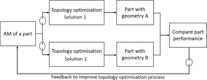
The use of topology optimization in AM of difficult-to-cut alloys showing a possible lack of understanding and expertise in AM (highlighted in circles)

-
Difficult-to-cut alloys produced via SLM or other AM processes usually require post-processing operations such as subjecting the part to thermal cycles to remove residual stresses and improve the mechanical properties. In addition, machining operations are performed to improve the accuracy and final shape of the part. Machining AM of difficult-to-cut alloys is challenging not only because of the present uncertainty in their mechanical and thermal properties but rather of how varied those properties could be using this process. The machinability of the part can therefore vary significantly, even a small change in material property such as its strength or hardness would require new cutting data which can be time-consuming and costly. Nowadays, hybrid machining — which is a combination of two or more machining technologies and other supporting processes such as cooling — is gaining more attention, especially for machining AM of difficult-to-cut alloys. High cutting forces and temperatures are some of the most challenging issues in machining difficult-to-cut alloys which can be minimised using hybrid machining technologies. For example, it is well known that using ultrasonic-assisted machining can minimise cutting forces and temperatures thanks to its unique cutting mechanisms. In addition, it is well known that the use of certain cooling technologies such as through tool cryogenic cooling can significantly reduce the cutting tool temperature and increase production rates. Hybrid machining becomes more important in AM of difficult-to-cut alloys as it can minimise the thermal effects on the part dimensional accuracy, surface finish and workpiece hardening. Moreover, according to cutting tool manufacturers, many industries are now adopting “green” machining initiatives to minimise energy consumption and waste for difficult-to-cut alloys.
-
Machine learning (ML) has been increasingly employed in different AM processes mainly focusing on planning during pre-manufacturing, parameter optimisation and in-process monitoring for quality control [158]. However, the lack of large data for training and testing from AM processes including SLM limits ML’s ability to identify all the trends and patterns in the fabrication process making it highly susceptible to errors due to biased predictions from biased training sets. It is also possible to use ML for automated fault detection during the fabrication process by analysing the shape and geometry of the part to spot fault occurrences and causing factors. The use of sensorial data obtained from different monitoring systems (thermal sensors and X-ray and computerised tomography) can provide real-time data to help identify defects on the build surface and internally (i.e., pores) [159], which can be then incorporated into ML models to possibly repair these defects or prevent their reoccurrence in the following layers. It is also important to focus future research on optimising and monitoring pre-fabrication factors such as powder particle shape and size as they greatly influence the melt pool quality and packing of the powder in the build. A suggestion is to find a way of producing optimal powder particle shapes and sizes, powder particle monitoring and categorisation to minimise its effect on the final part quality.
6 Conclusions
The use of selective laser melting has a large amount of promise for the manufacturing of components across a wide variety of application domains. The papers that were described in this review are possible for a complete study to be conducted for the very first time regarding the surface integrity of machined SLMed difficult-to-cut alloys. In this way, it was demonstrated that when applied to traditional difficult-to-cut alloy samples, this led to beneficial outcomes such as compressive stresses and reduced roughness, and also led to beneficial surface qualities when applied to SLM samples during the machining process. When looking at the findings of the difficult-to-cut alloy samples and the SLM samples side by side, there are, as was to be expected, some differences. On the other hand, as PBLF/SLM machine settings and post-treatment techniques such as heat treatment and machining affect the microstructure, defect, mechanical qualities, texture, and surface quality, so do the post-treatment treatments. Because of this, it is strongly recommended that these aspects be tuned and tailored to a specific application to receive the best results possible. Many powder alloys for SLM can be used in combination with post-processing treatments, making it a promising technique for the production of components with high format complexity that can be used in a variety of industries, such as nuclear power and aerospace. SLM can also produce components with good mechanical strength and fatigue life but are still inferior to traditionally manufactured parts (wrought or machined) [160]. Components made using SLM have the same mechanical strength and fatigue life as those made with more conventional methods of production. Finally, for difficult alloys that were laser melted using a selective laser melting (SLM), there was an in-depth examination of the connection between surface integrity and properties such as surface topography, microstructural morphology, and mechanical properties. As a consequence of this, this review study detailed the advantages and disadvantages of selective laser-melted difficult-to-cut alloys in terms of composition, categorisation, microstructure, defects, and features, as well as the development potential for both researchers and industry.
Availability of data and material
Not applicable.
Code availability
Not applicable.
References
Zhang M, Zhang B, Wen Y, Qu X (2022) Research progress on selective laser melting processing for nickel-based superalloy. Int J Miner Metall Mater 29(3). https://doi.org/10.1007/s12613-021-2331-1
Motallebi R, Savaedi Z, Mirzadeh H (2022) Additive manufacturing — a review of hot deformation behavior and constitutive modeling of flow stress. Curr Opin Solid State Mater Sci 26(3). https://doi.org/10.1016/j.cossms.2022.100992
Ji H et al (2021) Microstructure and machinability evaluation in micro milling of selective laser melted Inconel 718 alloy. J Mater Res Technol 14:348–362. https://doi.org/10.1016/j.jmrt.2021.06.081
Khanna N, Zadafiya K, Patel T, Kaynak Y, Rahman Rashid RA, Vafadar A (2021) Review on machining of additively manufactured nickel and titanium alloys. J Mater Res Technol 15:3192–3221. https://doi.org/10.1016/j.jmrt.2021.09.088
Ucak N, Cicek A, Aslantas K (2022) Machinability of 3D printed metallic materials fabricated by selectivelaser melting and electron beam melting: a review. J Manuf Process 80:414–457. https://doi.org/10.1016/j.jmapro.2022.06.023
Song B et al (2015) Differences in microstructure and properties between selective laser melting and traditional manufacturing for fabrication of metal parts: a review. Front Mech Eng 10(2):111–125. https://doi.org/10.1007/s11465-015-0341-2
Singla AK, Banerjee M, Sharma A, Singh J, Bansal A, Gupta MK, Khanna N, Shahi AS, Goyal DK (2021) Selective laser melting of Ti6Al4V alloy: Process parameters, defects and post-treatments. J Manuf Process 64:161–187. https://doi.org/10.1016/j.jmapro.2021.01.009
Zhai X, Jin L, Jiang J (2022) A survey of additive manufacturing reviews. Mater Sci Addit Manuf 1(4):21. https://doi.org/10.18063/MSAM.V1I4.21
Du C et al (2023) Pore defects in Laser Powder Bed Fusion: Formation mechanism, control method, and perspectives. J Alloys Compd 944:169215. https://doi.org/10.1016/J.JALLCOM.2023.169215
Rodrigues TA et al (2022) Wire and arc additive manufacturing of 316L stainless steel/Inconel 625 functionally graded material: development and characterization. J Mater Res Technol 21:237–251. https://doi.org/10.1016/J.JMRT.2022.08.169
Pérez-Ruiz JD, Marin F, Martínez S, Lamikiz A, Urbikain G, López de Lacalle LN (2022) Stiffening near-net-shape functional parts of Inconel 718 LPBF considering material anisotropy and subsequent machining issues. Mech Syst Signal Process 168:108675. https://doi.org/10.1016/J.YMSSP.2021.108675
Li S et al (2022) Controlling the columnar-to-equiaxed transition during directed energy deposition of Inconel 625. Addit Manuf 57:102958. https://doi.org/10.1016/J.ADDMA.2022.102958
Murr LE et al (2012) Fabrication of metal and alloy components by additive manufacturing: examples of 3D materials science. J Mater Res Technol 1(1):42–54. https://doi.org/10.1016/S2238-7854(12)70009-1
Coro A, Macareno LM, Aguirrebeitia J, de Lacalle LN (2019) A methodology to evaluate the reliability impact of the replacement of welded components by additive manufacturing spare parts. Metals (Basel) 9(9). https://doi.org/10.3390/met9090932
Liu G et al (2021) Additive manufacturing of structural materials. Mater Sci Eng R Reports 145:100596. https://doi.org/10.1016/j.mser.2020.100596
Katz-Demyanetz A, Popov VV, Kovalevsky A, Safranchik D, Koptyug A (2019) Powder-bed additive manufacturing for aerospace application: techniques, metallic and metal/ceramic composite materials and trends. Manuf Rev 6:5. https://doi.org/10.1051/mfreview/2019003
Gong G et al (2021) Research status of laser additive manufacturing for metal: a review. J Mater Res Technol 15:855–884. https://doi.org/10.1016/j.jmrt.2021.08.050
Maconachie T et al (2019) SLM lattice structures: properties, performance, applications and challenges. Mater Des 183:108137. https://doi.org/10.1016/j.matdes.2019.108137
Dhiman S, Singh M, Sidhu SS, Bahraminasab M, Pimenov DY, Mikolajczyk T (2021) Cubic lattice structures of Ti6Al4V under compressive loading: towards assessing the performance for hard tissue implants alternative. Materials (Basel) 14(14):3866. https://doi.org/10.3390/ma14143866
Korkmaz ME et al (2022) A short review on thermal treatments of titanium & nickel based alloys processed by selective laser melting. J Mater Res Technol 16:1090–1101. https://doi.org/10.1016/j.jmrt.2021.12.061
Sheshadri R et al (2021) Experimental investigation of selective laser melting parameters for higher surface quality and microhardness properties: Taguchi and super ranking concept approaches. J Mater Res Technol 14:2586–2600. https://doi.org/10.1016/j.jmrt.2021.07.144
Aktürk M, Boy M, Gupta MK, Waqar S, Krolczyk GM, Korkmaz ME (2021) Numerical and experimental investigations of built orientation dependent Johnson-Cook model for selective laser melting manufactured AlSi10Mg. J Mater Res Technol 15:6244–6259. https://doi.org/10.1016/j.jmrt.2021.11.062
Murr LE et al (2012) Metal fabrication by additive manufacturing using laser and electron beam melting technologies. J Mater Sci Technol 28(1):1–14. https://doi.org/10.1016/S1005-0302(12)60016-4
Alizadeh-Sh M, Marashi SPH, Ranjbarnodeh E, Shoja-Razavi R, Oliveira JP (2020) Prediction of solidification cracking by an empirical-statistical analysis for laser cladding of Inconel 718 powder on a non-weldable substrate. Opt Laser Technol 128:106244. https://doi.org/10.1016/J.OPTLASTEC.2020.106244
Teixeira Ó, Silva FJG, Ferreira LP, Atzeni E (2020) A review of heat treatments on improving the quality and residual stresses of the Ti–6Al–4V parts produced by additive manufacturing. Metals (Basel) 10(8):1006. https://doi.org/10.3390/met10081006
Zhang Z, Chu B, Wang L, Lu Z (2019) Comprehensive effects of placement orientation and scanning angle on mechanical properties and behavior of 316L stainless steel based on the selective laser melting process. J Alloys Compd 791:166–175. https://doi.org/10.1016/J.JALLCOM.2019.03.082
Miao X, Liu X, Lu P, Han J, Duan W, Wu M (2020) Influence of scanning strategy on the performances of go-reinforced ti6al4v nanocomposites manufactured by SLM. Metals (Basel) 10(10). https://doi.org/10.3390/met10101379
Yap CY et al (2015) Review of selective laser melting: materials and applications. Appl Phys Rev 2(4):041101. https://doi.org/10.1063/1.4935926
Gu H et al (2020) Multi-physics modelling of molten pool development and track formation in multi-track, multi-layer and multi-material selective laser melting. Int J Heat Mass Transf 151:119458. https://doi.org/10.1016/j.ijheatmasstransfer.2020.119458
Shen J et al (2021) In-situ synchrotron X-ray diffraction analysis of the elastic behaviour of martensite and H-phase in a NiTiHf high temperature shape memory alloy fabricated by laser powder bed fusion. Addit Manuf Lett 1:100003. https://doi.org/10.1016/J.ADDLET.2021.100003
Conde FF et al (2019) Effect of thermal cycling and aging stages on the microstructure and bending strength of a selective laser melted 300-grade maraging steel. Mater Sci Eng A 758:192–201. https://doi.org/10.1016/J.MSEA.2019.03.129
Rafi HK, Karthik NV, Gong H, Starr TL, Stucker BE (2013) Microstructures and mechanical properties of Ti6Al4V parts fabricated by selective laser melting and electron beam melting. J Mater Eng Perform 22(12):3872–3883. https://doi.org/10.1007/S11665-013-0658-0
Haan J, Asseln M, Zivcec M, Eschweiler J, Radermacher R, Broeckmann C (2015) Effect of subsequent hot isostatic pressing on mechanical properties of ASTM F75 alloy produced by selective laser melting. Powder Metall 58(3):161–165. https://doi.org/10.1179/0032589915Z.000000000236
Hosseini E, Popovich VA (2019) A review of mechanical properties of additively manufactured Inconel 718. Addit Manuf 30:100877. https://doi.org/10.1016/J.ADDMA.2019.100877
Qiu C, Adkins NJE, Attallah MM (2016) Selective laser melting of Invar 36: microstructure and properties. Acta Mater 103:382–395. https://doi.org/10.1016/J.ACTAMAT.2015.10.020
Braun J et al (2019) Molybdenum and tungsten manufactured by selective laser melting: analysis of defect structure and solidification mechanisms. Int J Refract Met Hard Mater 84:104999. https://doi.org/10.1016/J.IJRMHM.2019.104999
Wei C, Li L, Zhang X, Chueh YH (2018) 3D printing of multiple metallic materials via modified selective laser melting. CIRP Ann 67(1):245–248. https://doi.org/10.1016/J.CIRP.2018.04.096
Blakey-Milner B et al (2021) Metal additive manufacturing in aerospace: a review. Mater Des 209:110008. https://doi.org/10.1016/J.MATDES.2021.110008
Karmuhilan M, Kumanan S (2021) A review on additive manufacturing processes of Inconel 625. J Mater Eng Perform 1–10. https://doi.org/10.1007/S11665-021-06427-3/TABLES/5
DebRoy T et al (2018) Additive manufacturing of metallic components — process, structure and properties. Prog Mater Sci 92:112–224. https://doi.org/10.1016/J.PMATSCI.2017.10.001
Antony KC (1983) Wear-resistant cobalt-base alloys. JOM J Miner Met Mater Soc 35(2):52–60. https://doi.org/10.1007/BF03338205/METRICS
Chen H, Zhang Y, Giam A, Yan W (2022) Experimental and computational study on thermal and fluid behaviours of powder layer during selective laser melting additive manufacturing. Addit Manuf 102645. https://doi.org/10.1016/j.addma.2022.102645
Laguna OH, Lietor PF, Godino FJI, Corpas-Iglesias FA (2021) A review on additive manufacturing and materials for catalytic applications: milestones, key concepts, advances and perspectives. Mater Des 208:109927. https://doi.org/10.1016/j.matdes.2021.109927
Bustillos J, Kim J, Moridi A (2021) Exploiting lack of fusion defects for microstructural engineering in additive manufacturing. Addit Manuf 48:102399. https://doi.org/10.1016/j.addma.2021.102399
Laleh M et al (2020) Two and three-dimensional characterisation of localised corrosion affected by lack-of-fusion pores in 316L stainless steel produced by selective laser melting. Corros Sci 165:108394. https://doi.org/10.1016/j.corsci.2019.108394
Ran J, Sun X, Wei S, Chen Z, Zhao H (2020) Achieving Ti-5Al-4Sn-2Zr-1Mo-0.25Si-1Nb alloys with high strength and moderate ductility through selective laser melting. Materials (Basel) 13(23):1–17. https://doi.org/10.3390/MA13235527
Maity T, Chawake N, Kim JT, Eckert J, Prashanth KG (2018) Anisotropy in local microstructure–Does it affect the tensile properties of the SLM samples? Manuf Lett 15:33–37. https://doi.org/10.1016/j.mfglet.2018.02.012
Kunze K, Etter T, Grässlin J, Shklover V (2015) Texture, anisotropy in microstructure and mechanical properties of IN738LC alloy processed by selective laser melting (SLM). Mater Sci Eng A 620:213–222. https://doi.org/10.1016/j.msea.2014.10.003
Nguejio J, Szmytka F, Hallais S, Tanguy A, Nardone S, Godino Martinez M (2019) Comparison of microstructure features and mechanical properties for additive manufactured and wrought nickel alloys 625. Mater Sci Eng A 764:138214. https://doi.org/10.1016/J.MSEA.2019.138214
Koutiri I, Pessard E, Peyre P, Amlou O, De Terris T (2018) Influence of SLM process parameters on the surface finish, porosity rate and fatigue behavior of as-built Inconel 625 parts. J Mater Process Technol 255:536–546. https://doi.org/10.1016/J.JMATPROTEC.2017.12.043
Zhao X et al (2016) Comparison of the microstructures and mechanical properties of Ti–6Al–4V fabricated by selective laser melting and electron beam melting. Mater Des 95:21–31. https://doi.org/10.1016/J.MATDES.2015.12.135
Brandt M, Sun S, Leary M, Feih S, Elambasseril J, Liu Q (2013) High-value SLM aerospace components: from design to manufacture. Adv Mater Res 633:135–147. https://doi.org/10.4028/WWW.SCIENTIFIC.NET/AMR.633.135
Herzog D, Seyda V, Wycisk E, Emmelmann C (2016) Additive manufacturing of metals. Acta Mater 117:371–392. https://doi.org/10.1016/J.ACTAMAT.2016.07.019
Razavi SMJ, Avanzini A, Cornacchia G, Giorleo L, Berto F (2021) Effect of heat treatment on fatigue behavior of as-built notched Co-Cr-Mo parts produced by selective laser melting. Int J Fatigue 142:105926. https://doi.org/10.1016/J.IJFATIGUE.2020.105926
Antonysamy AA, Meyer J, Prangnell PB (2013) Effect of build geometry on the β-grain structure and texture in additive manufacture of Ti6Al4V by selective electron beam melting. Mater Charact 84:153–168. https://doi.org/10.1016/J.MATCHAR.2013.07.012
Astakhov VP (2010) Surface integrity — definition and importance in functional performance. In: Surface integrity in machining. Springer London, London, pp 1–35
Bigerelle M, Iost A (2007) A numerical method to calculate the Abbott parameters: a wear application. Tribol Int 40(9):1319–1334. https://doi.org/10.1016/j.triboint.2006.12.007
Pawlus P, Reizer R, Wieczorowski M, Krolczyk G (2020) Material ratio curve as information on the state of surface topography—a review. Precis Eng 65:240–258. https://doi.org/10.1016/j.precisioneng.2020.05.008
Franco LA, Sinatora A (2015) 3D surface parameters (ISO 25178–2): actual meaning of Spk and its relationship to Vmp. Precis Eng 40:106–111. https://doi.org/10.1016/j.precisioneng.2014.10.011
Jeng Y-R, Lin Z-W, Shyu S-H (2004) Changes of surface topography during running-in process. J Tribol 126(3):620–625. https://doi.org/10.1115/1.1759344
Mehl ACSB, Benegra M, Pintaude G (2021) Surface characterization of the seating platform of titanium implant processed with different textures. J Braz Soc Mech Sci Eng 43(3):130. https://doi.org/10.1007/s40430-021-02853-5
Lou S, Jiang X, Sun W, Zeng W, Pagani L, Scott PJ (2019) Characterisation methods for powder bed fusion processed surface topography. Precis Eng 57:1–15. https://doi.org/10.1016/j.precisioneng.2018.09.007
Shen J et al (2022) Gas tungsten arc welding of as-cast AlCoCrFeNi2.1 eutectic high entropy alloy. Mater Des 223:111176. https://doi.org/10.1016/J.MATDES.2022.111176
Shen J et al (2023) Microstructure and mechanical properties of gas metal arc welded CoCrFeMnNi joints using a 308 stainless steel filler metal. Scr Mater 222:115053. https://doi.org/10.1016/J.SCRIPTAMAT.2022.115053
Parrish G (1977) Influence of microstructure on properties of case-carburised components. Heat Treta Met. Accessed 07/01/2023
Li Z, Yang S, Liu B, Liu W, Kuai Z, Nie Y (2021) Simulation of temperature field and stress field of selective laser melting of multi-layer metal powder. Opt Laser Technol 140:106782. https://doi.org/10.1016/j.optlastec.2020.106782
Khan HM, Waqar S, Koç E (2022) Evolution of temperature and residual stress behavior in selective laser melting of 316L stainless steel across a cooling channel. Rapid Prototyp J 28(7):1272–1283. https://doi.org/10.1108/RPJ-09-2021-0237
Carraturo M, Kollmannsberger S, Reali A, Auricchio F, Rank E (2021) An immersed boundary approach for residual stress evaluation in selective laser melting processes. Addit Manuf 46:102077. https://doi.org/10.1016/j.addma.2021.102077
Ming W, Chen J, An Q, Chen M (2019) Dynamic mechanical properties and machinability characteristics of selective laser melted and forged Ti6Al4V. J Mater Process Technol 271:284–292. https://doi.org/10.1016/j.jmatprotec.2019.04.015
Morelo F, Grabarski MI, de Camargo Beltrão PA, Pintaude G (2017) Surface integrity of bored super duplex stainless steel SAF 2507. J Braz Soc Mech Sci Eng 39(7):2649–2658. https://doi.org/10.1007/s40430-016-0642-3
Yang T et al (2021) A review of diagnostics methodologies for metal additive manufacturing processes and products. Materials 14(17). https://doi.org/10.3390/ma14174929
Thompson A, Senin N, Giusca C, Leach R (2017) Topography of selectively laser melted surfaces: a comparison of different measurement methods. CIRP Ann 66(1):543–546. https://doi.org/10.1016/j.cirp.2017.04.075
Pérez-Ruiz JD, de Lacalle LNL, Urbikain G, Pereira O, Martínez S, Bris J (2021) On the relationship between cutting forces and anisotropy features in the milling of LPBF Inconel 718 for near net shape parts. Int J Mach Tools Manuf 170:103801. https://doi.org/10.1016/j.ijmachtools.2021.103801
Murakami Y, Endo M (1994) Effects of defects, inclusions and inhomogeneities on fatigue strength. Int J Fatigue 16(3):163–182. https://doi.org/10.1016/0142-1123(94)90001-9
Liu QC, Elambasseril J, Sun SJ, Leary M, Brandt M, Sharp PK (2014) The effect of manufacturing defects on the fatigue behaviour of Ti-6Al-4V specimens fabricated using selective laser melting. Adv Mater Res 891–892:1519–1524. https://doi.org/10.4028/www.scientific.net/AMR.891-892.1519
Vilaro T, Colin C, Bartout JD (2011) As-fabricated and heat-treated microstructures of the Ti-6Al-4V alloy processed by selective laser melting. Metall Mater Trans A Phys Metall Mater Sci 42(10):3190–3199. https://doi.org/10.1007/S11661-011-0731-Y
Gong H, Rafi K, Gu H, Starr T, Stucker B (2014) Analysis of defect generation in Ti–6Al–4V parts made using powder bed fusion additive manufacturing processes. Addit Manuf 1–4:87–98. https://doi.org/10.1016/j.addma.2014.08.002
Kobryn PA, Semiatin SL (2001) Mechanical properties of laser-deposited Ti-6Al-4V. Int Solid Free Fabr Symp 179–186
Zhou X et al (2015) 3D-imaging of selective laser melting defects in a Co–Cr–Mo alloy by synchrotron radiation micro-CT. Acta Mater 98:1–16. https://doi.org/10.1016/j.actamat.2015.07.014
Masuo H et al (2017) Effects of defects, surface roughness and HIP on fatigue strength of Ti-6Al-4V manufactured by additive manufacturing. Procedia Struct Integr 7:19–26. https://doi.org/10.1016/j.prostr.2017.11.055
Zhang X, Chen H, Xu L, Xu J, Ren X, Chen X (2019) Cracking mechanism and susceptibility of laser melting deposited Inconel 738 superalloy. Mater Des 183:108105. https://doi.org/10.1016/j.matdes.2019.108105
Zhang S (2013) Cracking behavior and formation mechanism of TC4 alloy formed by selective laser melting. J Mech Eng 49(23):21. https://doi.org/10.3901/JME.2013.23.021
Gu D et al (2012) Densification behavior, microstructure evolution, and wear performance of selective laser melting processed commercially pure titanium. Acta Mater 60(9):3849–3860. https://doi.org/10.1016/j.actamat.2012.04.006
Li R, Shi Y, Wang Z, Wang L, Liu J, Jiang W (2010) Densification behavior of gas and water atomized 316L stainless steel powder during selective laser melting. Appl Surf Sci 256(13):4350–4356. https://doi.org/10.1016/J.APSUSC.2010.02.030
Mercelis P, Kruth J (2006) Residual stresses in selective laser sintering and selective laser melting. Rapid Prototyp J 12(5):254–265. https://doi.org/10.1108/13552540610707013
Kempen K, Thijs L, Vrancken B, Buls S, Van Humbeeck J, Kruth JP (2013) Producing crack-free, high density M2 HSS parts by selective laser melting: pre-heating the baseplate. 24th Int. SFF Symp. - An Addit. Manuf. Conf. SFF 2013, no. August, pp 131–139
Thijs L, Verhaeghe F, Craeghs T, Van Humbeeck J, Kruth J-P (2010) A study of the microstructural evolution during selective laser melting of Ti–6Al–4V. Acta Mater 58(9):3303–3312. https://doi.org/10.1016/j.actamat.2010.02.004
Qiu C, Adkins NJE, Attallah MM (2013) Microstructure and tensile properties of selectively laser-melted and of HIPed laser-melted Ti–6Al–4V. Mater Sci Eng A 578:230–239. https://doi.org/10.1016/j.msea.2013.04.099
Haboudou A, Peyre P, Vannes AB, Peix G (2003) Reduction of porosity content generated during Nd:YAG laser welding of A356 and AA5083 aluminium alloys. Mater Sci Eng A 363(1):40–52. https://doi.org/10.1016/S0921-5093(03)00637-3
Carter LN et al (2016) Process optimisation of selective laser melting using energy density model for nickel based superalloys. Mater Sci Technol 32(7):657–661. https://doi.org/10.1179/1743284715Y.0000000108
Fedina T, Sundqvist J, Powell J, Kaplan AFH (2020) A comparative study of water and gas atomized low alloy steel powders for additive manufacturing. Addit Manuf 36:101675. https://doi.org/10.1016/j.addma.2020.101675
Thijs L, Kempen K, Kruth J-P, Van Humbeeck J (2013) Fine-structured aluminium products with controllable texture by selective laser melting of pre-alloyed AlSi10Mg powder. Acta Mater 61(5):1809–1819. https://doi.org/10.1016/j.actamat.2012.11.052
Wang Y, Shi J (2020) Effect of hot isostatic pressing on nanoparticles reinforced AlSi10Mg produced by selective laser melting. Mater Sci Eng A 788:139570. https://doi.org/10.1016/j.msea.2020.139570
Maskery I et al (2016) Quantification and characterisation of porosity in selectively laser melted Al–Si10–Mg using X-ray computed tomography. Mater Charact 111:193–204. https://doi.org/10.1016/j.matchar.2015.12.001
Bauereiß A, Scharowsky T, Körner C (2014) Defect generation and propagation mechanism during additive manufacturing by selective beam melting. J Mater Process Technol 214(11):2522–2528. https://doi.org/10.1016/j.jmatprotec.2014.05.002
Yasa E, Deckers J, Kruth J (2011) The investigation of the influence of laser re-melting on density, surface quality and microstructure of selective laser melting parts. Rapid Prototyp J 17(5):312–327. https://doi.org/10.1108/13552541111156450
Nagarajan B, Hu Z, Song X, Zhai W, Wei J (2019) Development of micro selective laser melting: the state of the art and future perspectives. Engineering 5(4):702–720. https://doi.org/10.1016/J.ENG.2019.07.002
Yadollahi A, Shamsaei N (2017) Additive manufacturing of fatigue resistant materials: challenges and opportunities. Int J Fatigue 98:14–31. https://doi.org/10.1016/j.ijfatigue.2017.01.001
Wang D, Liu Y, Yang Y, Xiao D (2016) Theoretical and experimental study on surface roughness of 316L stainless steel metal parts obtained through selective laser melting. Rapid Prototyp J 22(4):706–716. https://doi.org/10.1108/RPJ-06-2015-0078
Yamaguchi H, Fergani O, Wu P-Y (2017) Modification using magnetic field-assisted finishing of the surface roughness and residual stress of additively manufactured components. CIRP Ann 66(1):305–308. https://doi.org/10.1016/j.cirp.2017.04.084
Löber L, Flache C, Petters R, Kühn U, Eckert J (2013) Comparison of different post processing technologies for SLM generated 316l steel parts. Rapid Prototyp J 19(3):173–179. https://doi.org/10.1108/13552541311312166
Konečná R, Nicoletto G, Kunz L, Bača A (2016) Microstructure and directional fatigue behavior of Inconel 718 produced by selective laser melting. Procedia Struct Integr 2:2381–2388. https://doi.org/10.1016/j.prostr.2016.06.298
Mumtaz K, Hopkinson N (2009) Top surface and side roughness of Inconel 625 parts processed using selective laser melting. Rapid Prototyp J 15(2):96–103. https://doi.org/10.1108/13552540910943397
Kelley PF, Saigal A, Vlahakis JK, Carter A (2015) Tensile and fatigue behavior of direct metal laser sintered (DMLS) Inconel 718. ASME 2015 International Mechanical Engineering Congress and Exposition. https://doi.org/10.1115/IMECE2015-50937
Xu Z, Hyde CJ, Tuck C, Clare AT (2018) Creep behaviour of Inconel 718 processed by laser powder bed fusion. J Mater Process Technol 256:13–24. https://doi.org/10.1016/j.jmatprotec.2018.01.040
Yan C, Hao L, Hussein A, Young P, Raymont D (2014) Advanced lightweight 316L stainless steel cellular lattice structures fabricated via selective laser melting. Mater Des 55:533–541. https://doi.org/10.1016/j.matdes.2013.10.027
Kaynak Y, Tascioglu E (2020) Post-processing effects on the surface characteristics of Inconel 718 alloy fabricated by selective laser melting additive manufacturing. Prog Addit Manuf 5(2):221–234. https://doi.org/10.1007/s40964-019-00099-1
Masseling L (2015) Reduction of surface roughness of Slm components by means of modulated laser. Annu Rep 69572. Accessed 07/01/2023
Simoni F, Huxol A, Villmer F-J (2021) Improving surface quality in selective laser melting based tool making. J Intell Manuf 32(7):1927–1938. https://doi.org/10.1007/s10845-021-01744-9
Zeng Y, Wang K, Mello BC, Wang Z, Brown CA (2014) Multi-scale evaluations of the roughness of surfaces made by additive manufacturing. Proc - ASPE 2014 Spring Top Meet Dimens Accuracy Surf Finish Addit Manuf no. January, pp 157–162
Alrbaey K, Wimpenny D, Tosi R, Manning W, Moroz A (2014) On optimization of surface roughness of selective laser melted stainless steel parts: a statistical study. J Mater Eng Perform 23(6):2139–2148. https://doi.org/10.1007/s11665-014-0993-9
Yasa E, Kruth J-P (2011) Application of laser re-melting on selective laser melting parts. Adv Prod Eng Manag 6:259–270
Kaynak Y, Kitay O (2019) The effect of post-processing operations on surface characteristics of 316L stainless steel produced by selective laser melting. Addit Manuf 26:84–93. https://doi.org/10.1016/j.addma.2018.12.021
Zhang S, Wei Q, Cheng L, Li S, Shi Y (2014) Effects of scan line spacing on pore characteristics and mechanical properties of porous Ti6Al4V implants fabricated by selective laser melting. Mater Des 63:185–193. https://doi.org/10.1016/j.matdes.2014.05.021
Rodriguez-Vidal E, Matthews DTA, Sáenz de Viteri V, Korver F, Wentink DJ, Quintana I (2020) Surface design and texturing of strip steel using nanosecond pulsed lasers for simulated roughness transfer and paint appearance. J Mater Process Technol 275:116365. https://doi.org/10.1016/j.jmatprotec.2019.116365
Dursun G, Ibekwe S, Li G, Mensah P, Joshi G, Jerro D (2020) Influence of laser processing parameters on the surface characteristics of 316L stainless steel manufactured by selective laser melting. Mater Today Proc 26:387–393. https://doi.org/10.1016/j.matpr.2019.12.061
Valente EH, Gundlach C, Christiansen TL, Somers MAJ (2019) Effect of scanning strategy during selective laser melting on surface topography, porosity, and microstructure of additively manufactured Ti-6Al-4V. Appl Sci 9(24). https://doi.org/10.3390/app9245554
Campbell RI, Martorelli M, Lee HS (2002) Surface roughness visualisation for rapid prototyping models. Comput Des 34(10):717–725. https://doi.org/10.1016/S0010-4485(01)00201-9
Covarrubias EE, Eshraghi M (2018) Effect of build angle on surface properties of nickel superalloys processed by selective laser melting. JOM 70(3):336–342. https://doi.org/10.1007/s11837-017-2706-y
Yasa E, Kruth J-P (2011) Microstructural investigation of selective laser melting 316L stainless steel parts exposed to laser re-melting. Procedia Eng 19:389–395. https://doi.org/10.1016/j.proeng.2011.11.130
Yadroitsev I, Krakhmalev P, Yadroitsava I, Johansson S, Smurov I (2013) Energy input effect on morphology and microstructure of selective laser melting single track from metallic powder. J Mater Process Technol 213(4):606–613. https://doi.org/10.1016/j.jmatprotec.2012.11.014
Zhou X et al (2015) Textures formed in a CoCrMo alloy by selective laser melting. J Alloys Compd 631:153–164. https://doi.org/10.1016/j.jallcom.2015.01.096
Jadhav SD, Dadbakhsh S, Goossens L, Kruth J-P, Van Humbeeck J, Vanmeensel K (2019) Influence of selective laser melting process parameters on texture evolution in pure copper. J Mater Process Technol 270:47–58. https://doi.org/10.1016/j.jmatprotec.2019.02.022
Popovich A, Sufiiarov V, Polozov I, Borisov E, Masaylo D, Orlov A (2016) Microstructure and mechanical properties of additive manufactured copper alloy. Mater Lett 179:38–41. https://doi.org/10.1016/j.matlet.2016.05.064
Chen J, Wang X, Pan Y (2019) Influence of laser power and scan speed on the microstructure and properties of GH4169 alloy prepared by selective laser melting. IOP Conf Ser Mater Sci Eng 688(3):33064. https://doi.org/10.1088/1757-899X/688/3/033064
Chen Z et al (2022) Effect of laser scanning speed on the microstructure and mechanical properties of laser-powder-bed-fused K418 nickel-based alloy. Materials (Basel) 15(9). https://doi.org/10.3390/ma15093045
Attar H, Calin M, Zhang LC, Scudino S, Eckert J (2014) Manufacture by selective laser melting and mechanical behavior of commercially pure titanium. Mater Sci Eng A 593:170–177. https://doi.org/10.1016/J.MSEA.2013.11.038
Wang P, Hua Chen F, Eckert J, Pilz S, Scudino S, Prashanth KG (2021) Microstructural evolution and mechanical properties of selective laser melted Ti-6Al-4V induced by annealing treatment. J Cent South Univ 28(4):1068–1077. https://doi.org/10.1007/S11771-021-4680-3
Sun W, Ma Y, Huang W, Zhang W, Qian X (2020) Effects of build direction on tensile and fatigue performance of selective laser melting Ti6Al4V titanium alloy. Int J Fatigue 130:105260. https://doi.org/10.1016/J.IJFATIGUE.2019.105260
Jiao ZH, Xu RD, Yu HC, Wu XR (2017) Evaluation on tensile and fatigue crack growth performances of Ti6Al4V alloy produced by selective laser melting. Procedia Struct Integr 7:124–132. https://doi.org/10.1016/J.PROSTR.2017.11.069
Simonelli M, Tse YY, Tuck C (2014) Effect of the build orientation on the mechanical properties and fracture modes of SLM Ti–6Al–4V. Mater Sci Eng A 616:1–11. https://doi.org/10.1016/J.MSEA.2014.07.086
Chen L, Sun Y, Li L, Ren X (2020) Microstructural evolution and mechanical properties of selective laser melted a nickel-based superalloy after post treatment. Mater Sci Eng A 792:139649. https://doi.org/10.1016/J.MSEA.2020.139649
Chlebus E, Gruber K, Kuźnicka B, Kurzac J, Kurzynowski T (2015) Effect of heat treatment on the microstructure and mechanical properties of Inconel 718 processed by selective laser melting. Mater Sci Eng A 639:647–655. https://doi.org/10.1016/J.MSEA.2015.05.035
Murr LE et al (2009) Microstructure and mechanical behavior of Ti–6Al–4V produced by rapid-layer manufacturing, for biomedical applications. J Mech Behav Biomed Mater 2(1):20–32. https://doi.org/10.1016/J.JMBBM.2008.05.004
Delannay F, Pardoen D, Colin C (2005) Equilibrium distribution of liquid during liquid phase sintering of composition gradient materials. Acta Mater 53(6):1655–1664. https://doi.org/10.1016/J.ACTAMAT.2004.12.015
Xu ZW, Liu A, Wang XS (2019) The influence of building direction on the fatigue crack propagation behavior of Ti6Al4V alloy produced by selective laser melting. Mater Sci Eng A 767:138409. https://doi.org/10.1016/J.MSEA.2019.138409
Rong T, Gu D, Shi Q, Cao S, Xia M (2016) Effects of tailored gradient interface on wear properties of WC/Inconel 718 composites using selective laser melting. Surf Coat Technol 307:418–427. https://doi.org/10.1016/J.SURFCOAT.2016.09.011
Buchkremer S, Klocke F, Döbbeler B, Abouridouane M, Meurer M (2017) Thermodynamics-based Interpretation of White Layer Formation in Metal Cutting. Procedia CIRP 58:370–374. https://doi.org/10.1016/J.PROCIR.2017.03.328
Klocke F, Hensgen L, Klink A, Ehle L, Schwedt A (2016) Structure and composition of the white layer in the wire-EDM process. Procedia CIRP 42:673–678. https://doi.org/10.1016/J.PROCIR.2016.02.300
Lamim TS, Bernardelli EA, Bendo T, Mello CH, Binder C, Klein AN (2019) Duplex surface treatment of sintered iron by plasma nitriding and plasma carburizing at low temperature. Surf Coat Technol 375:911–919. https://doi.org/10.1016/J.SURFCOAT.2019.07.068
Writzl V, Lima MSF, Guesser WL, Possoli FAA, das Neves JCK, Borges PC (2021) Influence of laser-hardening on microstructure and hardness of plasma-nitrided compacted graphite iron. Opt Laser Technol 144:107441. https://doi.org/10.1016/J.OPTLASTEC.2021.107441
Luisa S, Contuzzi N, Angelastro A, Domenico A (2010) Capabilities and performances of the selective laser melting process. New Trends Technol Devices Comput Commun Ind Syst. https://doi.org/10.5772/10432
Casavola C, Campanelli LS, Pappalettere C (2008) Experimental analysis of residual stresses in the selective laser melting process. In Proceedings of the 11th International Congress and Exhibition on Experimental and Applied Mechanics 3:1479–1486
Ali H, Ghadbeigi H, Mumtaz K (2018) Effect of scanning strategies on residual stress and mechanical properties of selective laser melted Ti6Al4V. Mater Sci Eng A 712:175–187. https://doi.org/10.1016/j.msea.2017.11.103
Chen J, Xue L (2010) Process-induced microstructural characteristics of laser consolidated IN-738 superalloy. Mater Sci Eng A 527(27):7318–7328. https://doi.org/10.1016/j.msea.2010.08.003
Lu Y et al (2015) Study on the microstructure, mechanical property and residual stress of SLM Inconel-718 alloy manufactured by differing island scanning strategy. Opt Laser Technol 75:197–206. https://doi.org/10.1016/j.optlastec.2015.07.009
Casavola C, Campanelli SL, Pappalettere C (2008) Preliminary investigation on distribution of residual stress generated by the selective laser melting process. J Strain Anal Eng Des 44(1):93–104. https://doi.org/10.1243/03093247JSA464
Mugwagwa L, Dimitrov D, Matope S, Becker T (2016) A methodology to evaluate the influence of part geometry on residual stresses in selective laser melting. Int Conf Compet Manuf 1(January):133–139
Kovaleva I, Kovalev O, Smurov I (2014) Model of heat and mass transfer in random packing layer of powder particles in selective laser melting. Phys Procedia 56:400–410. https://doi.org/10.1016/j.phpro.2014.08.143
Ganeriwala R, Zohdi TI (2014) Multiphysics modeling and simulation of selective laser sintering manufacturing processes. Procedia CIRP 14:299–304. https://doi.org/10.1016/j.procir.2014.03.015
Yadroitsev I, Yadroitsava I, Bertrand P, Smurov I (2012) Factor analysis of selective laser melting process parameters and geometrical characteristics of synthesized single tracks. Rapid Prototyp J 18(3):201–208. https://doi.org/10.1108/13552541211218117
Vrancken B, Wauthle R, Kruth JP, Van Humbeeck J (2013) Study of the influence of material properties on residual stress in selective laser melting. 24th Int SFF Symp - An Addit Manuf Conf SFF 2013, pp 393–407
Gusarov AV, Malakhova-Ziablova IS, Pavlov MD (2013) Thermoelastic residual stresses and deformations at laser treatment. Phys Procedia 41:896–903. https://doi.org/10.1016/j.phpro.2013.03.164
Kempen K, Thijs L, Vrancken B, Buls S, Van Humbeek J, Kruth J-P (2013) Lowering thermal gradients in selective laser melting by pre-heating the baseplate. In: Solid Freeform Fabrication Symposium, Austin, pp 131–139. Accessed 07/01/2023
Shiomi M, Osakada K, Nakamura K, Yamashita T, Abe F (2004) Residual stress within metallic model made by selective laser melting process. CIRP Ann 53(1):195–198. https://doi.org/10.1016/S0007-8506(07)60677-5
Jhabvala J, Boillat E, Antignac T, Glardon R (2010) On the effect of scanning strategies in the selective laser melting process. Virtual Phys Prototyp 5(2):99–109. https://doi.org/10.1080/17452751003688368
Kruth J-P, Deckers J, Yasa E, Wauthlé R (2012) Assessing and comparing influencing factors of residual stresses in selective laser melting using a novel analysis method. Proc Inst Mech Eng B J Eng Manuf 226(6):980–991. https://doi.org/10.1177/0954405412437085
Wang C, Tan XP, Tor SB, Lim CS (2020) Machine learning in additive manufacturing: state-of-the-art and perspectives. Addit Manuf 36:101538. https://doi.org/10.1016/j.addma.2020.101538
Wu Z et al (2023) High frequency beam oscillation keyhole dynamics in laser melting revealed by in-situ x-ray imaging. Commun Mater 4(1):5. https://doi.org/10.1038/s43246-023-00332-z
Yates JR, Efthymiadis P, Antonysamy AA, Pinna C, Tong J (2019) Do additive manufactured parts deserve better? Fatigue Fract Eng Mater Struct 42(9):2146–2154. https://doi.org/10.1111/ffe.13092
Author information
Authors and Affiliations
Corresponding authors
Ethics declarations
Ethics approval
Not applicable.
Consent to participate
Not applicable.
Consent for publication
Not applicable.
Conflict of interest
The authors declare no competing interests.
Additional information
Publisher's Note
Springer Nature remains neutral with regard to jurisdictional claims in published maps and institutional affiliations.
Rights and permissions
Open Access This article is licensed under a Creative Commons Attribution 4.0 International License, which permits use, sharing, adaptation, distribution and reproduction in any medium or format, as long as you give appropriate credit to the original author(s) and the source, provide a link to the Creative Commons licence, and indicate if changes were made. The images or other third party material in this article are included in the article's Creative Commons licence, unless indicated otherwise in a credit line to the material. If material is not included in the article's Creative Commons licence and your intended use is not permitted by statutory regulation or exceeds the permitted use, you will need to obtain permission directly from the copyright holder. To view a copy of this licence, visit http://creativecommons.org/licenses/by/4.0/.
About this article

Cite this article
Pimenov, D.Y., Berti, L.F., Pintaude, G. et al. Influence of selective laser melting process parameters on the surface integrity of difficult-to-cut alloys: comprehensive review and future prospects. Int J Adv Manuf Technol 127, 1071–1102 (2023). https://doi.org/10.1007/s00170-023-11541-8
Received:
Accepted:
Published:
Issue Date:
DOI: https://doi.org/10.1007/s00170-023-11541-8