
Abstract
Progress in applied research for sustainable machine tools and forming technologies bases upon industrial and environmental requirements for resource efficiency. Relevant technical trends base upon impact studies and applied research projects on the lifecycle resource consumption for manufacturing processes and systems. This paper gives an overview about a unified methodological approach of the evaluation of resource efficiency of machine tools. It answers the scientific question on sustainability: which technological parameters and machine tool characteristics lead to their lowest resource consumption/losses and part manufacturing costs. Therefore, the method allows to consider them as an energy-information model, in which the transformation of any forms and types of energy, material, and information takes place. It is shown that innovative hollow shaft forming technologies become sustainable alternatives to cutting technologies. A smart factory uses digitalization, manufacturing data management, and self-learning methods for resource efficiency. Sustainable production requires robust and error-free machining processes. Therefore, a collision prevention system protects machining centers and work pieces from collisions in real time will be presented. The gathered information about the product and its properties as well as manufacturing data builds a digital twin and enables a prediction of the resource consumption in smart factories.
1 Introduction
Physical resource usage is limited by their availability, sustainability, and environmental regulations, as well as cost constraints. Manufacturing processes trend towards decarbonization, renewable energies, and a circular economy. A paradigm change is required from “maximum profit realized by minimum funds” to “maximum added value from minimum resources,” combining manufacturing technologies with higher energy efficiency and less environmental footprint [1, 2] proposes an integrated approach for the evaluation of machine tools consisting of methodological proposals for the measurement of energy consumption, modeling of energy flows, and simulative analysis of the energy-saving potentials as well as an energy-oriented life cycle costing concept. [3, 4] introduce a resource consumption classification based on relevant physical relations and efficiency match between the real and target values. [5] states resource efficiency class (energy, material, information) and OEE class (performance, availability, quality, manufacturing costs) as key performance indicators for sustainable machine tools. Integrated methodology for synthesis, design, dimensioning, test and evaluation of manufacturing systems, processes, and environment becomes digital measureable and comparable. [6] presents the energetic limit for the attainability of associated cutting processes, describing the allowable speed of materials processing by the machine tools. Today’s process velocities are far away from theoretical values for crack propagation velocities. Not only the process speed is limiting the interaction between the tool and the work piece, but also the energy, the process temperature, the dynamic stability, the tool lifetime, and the machine tool stiffness.
Trends towards individual products lead to single part manufacturing, but serial production technologies have a higher sustainability potential. Progress in applied research for sustainable machine tools and forming technologies bases on resource efficiency and digitalization, referenced in this paper to impact studies and applied research projects.
2 Sustainable machine tools
2.1 Methodological approach
Machine tools fulfil technological requirements of manufacturing processes for part shaping, material cohesion, and mechanical property change. Machine tool users apply the key performance indicator “overall equipment effectiveness (OEE),” which integrates efficiency values for productivity, availability, and quality, targeting minimal part manufacturing costs [4] in order to optimize the process chain. Sustainable machine tools have a high resource consumption class defined by performance, availability, quality, and life cycle costs. Therefore, a scientific question on sustainability arises: which technological parameters and machine tool characteristics lead to their lowest resource consumption/losses and part manufacturing costs? [5]
A unified methodological approach to the evaluation of resource efficiency Ere of machine tools allows considering them as an energy-information model, in which the transformation of any forms and types of energy, material, and information takes place. Figure 1 shows an input resource consumption (energy, material, information) by sustainable machine tools for manufacturing technologies. Machine tools and manufacturing technologies deliver material goods. Digitalization is able to generate a value added and to increase their OEE (performance, availability, quality).

Sustainable machine tools and technologies
The concept of efficiency is considered a relative efficiency and characterizes the degree of use of any resource. Therefore, the ratio of volumes (energies, capacities, material, information, time, etc.) at the output of Ej and at the input of Ei is an assessment of the efficiency Ee [7].
Consequently, a sustainable machine tool (see technical system in Fig. 1) is relating to multicriteria for resource consumption following (1) (Fig. 2):
-
Energy efficiency\( {E}_e^e \)
-
Material efficiency \( {E}_e^m \)
-
Information efficiency \( {E}_e^i \)

Resource consumption model
Energy consumption is the integral of power consumption over time under process loads.
The energy of the physical process is equal to the work of the generalized force Fi at the generalized distance Li:
The product of a process force and velocity characterize the power consumption in (4).
Machine tools require dynamic force and velocity reserves above the process loads. Drive vibrations near natural frequencies cause contour deviations, resulting in energy losses. Therefore, a VDI directive [8] prescribes tests for step response and system oscillations at natural frequencies higher than process frequencies (escaping drive resonances). It defines the energy efficiency ε as an integral energy characteristic of the sequence of motion. The energy efficiency ε is the ratio of energy output to energy consumed during the cycle time Tc.
In this formula, Tc is the cycle time of a periodic motion, or a duration of a sequence of motions, pe(t) is the electrical power input (function of time), and pL(t) is the power output of the process (function of time).
Lightweight machine structures have a lower mass for higher accelerations, but may have a lower stiffness. Parallel kinematics have a high structural stiffness thanks to closed kinematic chains, requiring direct drives and encoders for a precision motion.
Material efficiency \( {\mathrm{E}}_{\mathrm{e}}^{\mathrm{m}} \) is characterized by the ratio of output to the input material consumption. Productivity is the rate of material change in shape, mechanical properties, and surface quality in time. The target for material efficiency is defined by minimum material losses (chips) and highest productivity. On the other hand, motor spindles for high-speed cutting and high-productive cutting cause higher power losses and higher temperatures, decreasing their energy efficiency.
Information efficiency \( {E}_e^i \) is the ratio of the output to input amount of information. The total amount of information consists of information about the product and its properties Iw, physical process If, and process control Ic. Servo drives, sensors, and control systems realize automatic functions supported by processors, memory, and information interfaces. A high manufacturing accuracy of goods requires an acquisition and comparison of properties to standardized values. Increasing accuracy requirements become comparable to dynamic and elastic deviations in the equipment stiffness under process loads [6].
A multicriteria optimization for resource efficiency will analyze the product of the energy, material, and information efficiency. Electric energy consumption is dominating the resource efficiency during the lifetime of machine tools, while material consumption is dominating in the manufacturing processes. Digitalization will deliver a value added and information efficiency, when targeting zero waste manufacturing. To show how this can be realized, the next chapter describes a collision avoidance method, which uses information given by the NC control of a machine tool to prevent collisions resulting in less waste and reduced downtimes which supports the goal of sustainability.
2.2 Sustainability through collision avoidance
Incorrect NC programs, e.g., during the commissioning phase, and operating errors can lead to unwanted collisions in the workspace of the machine tool resulting in high repair costs (up to 20,000 € [9]). However, major damages can be much more expensive. There are several sensor-based solutions to overcome this problem, e.g., using cameras [10] or integrated sensors to recognize overloads in the spindle [9]. However, sensor-based solutions are often limited in several ways, e.g., camera approaches are problematic when using cooling lubricants. Therefore, the TU Chemnitz and the Fraunhofer IWU developed a sensorless collision avoidance system based on a virtual model to detect potential collision cases and to brake or even stop the machine before a collision occurs.
The basic idea is to create a virtual 3D model of the machine tool, which moves like the real one and to use this model to detect collisions in advance. The base architecture of the system is shown in Fig. 3.

Base architecture of collision avoidance system
The detection software runs on an external industry PC (IPC) to avoid additional time-consuming calculations on the CNC. Therefore, it is linked with the bus system of the machine to establish a connection with the CNC to get real-time data like axis positions, feed rates, etc. The data is transferred in the interpolation cycle of the CNC to get a reasonable real-time behavior of the system. The communication between CNC and IPC takes place bidirectional, because the IPC delivers back the result of the collision check. In case of a detected collision danger, the CNC decelerates the machine tool to avoid damages. This is achieved by influencing the override, which has the advantage to slow down the axes but to retain the trajectory of the tool center point. To prevent collisions, the system must detect them before they occur. To achieve this, it is necessary to consider the braking distance for all moving components of the machine tool in the virtual model. The braking distances itself depend on the current feed rate, acceleration, and jerk parameters. It must be considered that components can have multiple movement directions depending on the kinematic structure. Based on the braking distances, a braking volume can be defined, which will be passed during the braking process. Determining this braking volume is not trivial and takes high computational efforts. It is not applicable to do it in real time in the IPO cycle.
Therefore, the developed system uses static hulls created beforehand for several feed rate steps. This is exemplarily illustrated in Fig. 4 by two hulls: an outer one (e.g., for maximum feed) and an inner hull (e.g., 20% of the maximum feed). If the system detects a collision between hulls of the same feed rate level (or between hull and static geometry), a feed rate reduction to the next lower feed rate level is triggered. If the innermost hulls are involved in a collision, the machine will be stopped before a real collision occurs with.

Principle of hull collision detection [11]
The overall distance for a hull consists of a reaction way, the braking way, and (if it is not the innermost hull) the aggregated distances of all enclosed hulls. Additionally, a security distance is applied. For example, the braking distances for the hulls for a component with a maximum feed rate of 25 m/s and an acceleration of 5 m/s2 are between 2 (innermost hull) and 82 mm (outermost hull for maximum feed rate).
The static hull approach is a compromise between flexibility and performance. While collision checking of static meshes can be done very fast with common techniques, the hulls are calculated for fix parameter setups. Therefore, the braking volume is greater than necessary in most cases. This can lead to unintended process influence (unnecessary stops or reduced production speed). Tests have shown that three hull levels are a reasonable choice for common processes to reduce this influence. It is also possible to gain more flexibility and to further reduce unnecessary stops by integrating a condition system [12]. Including further information like speeds and clamping signals allows to distinguish situations and to choose between smaller specialized hulls. This increases the amount of hulls, but the smaller volumes reduce the process influence significantly.
The presented collision avoidance system influences several attributes of the production. It has an effect on the availability of the machines. Fewer collisions mean fewer downtimes for repairing and therefore the overall availability increases. The benefit for a specific machine tool cannot be stated in a general manner. The impact highly depends on the intended use. While in mass production the effect is small, it has a greater impact for the production of small and very small series and on individual production. Collision avoidance also generates an added value because fewer repairs mean fewer repairing costs. It can also increase the lifespan of machine components where damages are too high for repairing and a replacement would be necessary. Beneath the availability and the added value, the productivity can also be influenced in two ways. Braking or even stopping machines increases production time, which results in decreased productivity. However, if the collision avoidance system is only used during the initial setup of new NC programs, it can save time because the machine setters can act faster with the protection of the system. For example, the setup time of 8 h for a complex process can be halved for an assumed average speed advantage of 50% with the activated collision prevention system. Therefore, in this fictional case, 4 h working time can be saved. Prevented collisions avoid downtimes for repairing which also has a positive effect in the productivity and therefore, on the overall equipment effectiveness (OEE). In addition, material necessary for repairing or substituting damaged machine parts will be saved.
3 Sustainable forming technologies
Sustainable technologies have a high resource efficiency, defined by high energy, material and information efficiency as well as low environmental footprint. Generally, forming technologies have a higher material efficiency in contrast to milling processes.
Innovative hollow shaft forming technologies become sustainable alternatives to cutting technologies (spin extrusion, axial forming, and hydroforming).
A smart forming process chain for hollow shaft forming will integrate the following machine tools for incremental forming into an advanced manufacturing cell (Fig. 5):
-
1.
Cross-wedge rolling machine tool RBQ
-
2.
Spin extrusion machine tool BDM2000
-
3.
Rotary swaging machine tool HA 101-1
-
4.
Gear forming-axial forming machine tool Aximus
-
5.
Gear rolling machine tool ROLLEX
-
6.
Flexible clamping and handling devices
Fig. 5 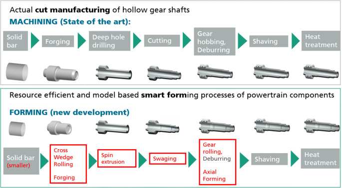
Machining and forming process chains

The development of the illustrated hollow gear with a final mass of 2.3 kg leads to 40% material savings.
Smart forming process reduces material consumption by more than 64%, energy by more than 68%, and causes 78% less scrap. This lightweight design shows further potential for customers to optimize the powertrain components in its environment and to reduce material input for another 10%.
4 Smart factory and virtual twin
Information efficiency expresses the ratio of output and input information. The total amount of information consists of information about the product and its properties, physical process, and process control.
4.1 Smart factory
The structural changes in industrial manufacturing have become increasingly important for businesses as well as for industrial associations and stakeholders from politics and society. In future production systems, the highest priority will still be minimum processing times and minimum stocks as well as maximum timeliness. The achievement of these objectives is decisively influenced by the selection of the correct control strategies. Additional goals, such as resource efficiency and carbon neutral production, further increase the complexity of the factory.
A smart factory uses digitalization, manufacturing data management, and self-learning methods for resource efficiency. A methodology on digitalization for sustainable machine tools and forming technologies investigates the potential of digital engineering, sustainable technologies, and machine tools. New approaches for data transfer inside a smart factory are shown in Fig. 6.

Digitalization for industry 4.0
The smart factory in the industry 4.0 production chain uses data as a core component and resource. Derived from transparent and flexible business models, the products with specific characteristics and material properties bring their data to the machines and processes of the smart factory. The processes automatically adapt to these values and the necessary process chains configure based on available machines, machine times, and necessary machining operations for the work piece as well as for the factory planning and logistics. Everything is based on historical and live data. The human is still an important guarantor for the production of the future, on the one hand as an intelligent problem solver in case when problems occur and on the other hand as the final decision maker and observer. However, data is the virtual fuel of the future production and the digital twin becomes as important as the real product and generates additional values for the customer and for the manufacturer. Automatic quality inspection systems use self-learning methods for pattern recognition and feature extraction for higher material efficiency.
Holistic concepts for linking manufacturing, information technology, and business organization will enable value-added creation from linked data and models towards smart products and services. Digitalization and cause-effect relationships do link manufacturing systems, processes, products with resource savings, and cost efficiency.
4.2 Digital engineering
Digital engineering has a high information efficiency, defined by added values derived from knowledge, software, and service. The law of logics reflects deterministic finite-state automates, but probabilistic calculations can predict events in the future space and time. Information exchange rates are confronted with transfer speed causing latency limits. Especially simulation is extending real manufacturing systems and processes (in space, time) by virtual properties and parameters, which are not accessible by a human (imperfect sensing, safety measures, and prediction probability). To underpin this statement, below two examples will be explained, where real-time simulations can create advantageous effects in the daily production.
4.3 Virtual twin extending the digital twin
Even if the development of support systems like predictive maintenance and condition monitoring helps to optimize processes, reduce system failures, and make processes more fail-safe, they only consider the process chain itself. The idea of a digital twin (or digital shadow [13], or digital artefact [14]) is to consolidate all relevant data (product, process, or factory level). Using this data, in combination with several specific data processing and analysis methods, the digital twin is one additional step optimize energy and resource efficiency. Already today, the use of the digital twin shows advantages of an increased networking of machines which helps to save energy, reduce scrap, and create a more efficient process chain. Grieves and Vickers [15] described the basic principles of the digital twin as the combination of consistent data with real data management. One use case of digital twins is predictive maintenance. In this case, the twin is used to predict when a machine tool will fail or when there will be a suitable maintenance window. Another use case is the transfer of process information for highly integrated process chains like the production of high-performance components. Due to processes like selective laser melting, thermal stresses occur in the work piece [16]. These stresses have a negative effect on the material properties and can lead to cracks in the surface during not adjusted post-processing. For this use case, it is essential for the product quality to consider the previous process steps. If the twin “knows” where the tensions most likely are, the following processes can react to it. The reactions could be a more efficient path planning strategy for milling. This means that the full potential of the planned process chain can be exploited from batch size one onwards. This ensures that less waste is produced.
To expand the potential of the digital twin, TU Chemnitz developed and defined a special form of the digital twin—the “virtual twin.” The virtual twin enhances the digital twin with time-based and location-dependent virtual 3D models. This means that data are visualized at the right position to the right time point dependent on the current data managed by the system.
The use of virtual twins provides two crucial advantages: At first, important information of all processes is available in real time at any time. Therefore, the users do not have to wait for the data transmission and preparation, which is a significant advantage especially for time-sensitive processes or failures during the production. The other advantage of a virtual twin is that all data along the process chain can be displayed and evaluated in relation to a virtual 3D model of the machine/process chain with a high-performance 3D engine.
By using this engine, it is possible to significantly improve the representation compared to a CAD representation and thus to use new visualization techniques. This allows displaying individual and contextual information without an installed CAD system. This twin also enables real-time monitoring of processes on machine tools, e.g., the force control of a combined milling and burnishing process in one clamping situation [17] (see right side of Fig. 7). The individual presentation of information also allows customizing the data representation to the level of knowledge of the user. In this way, an experienced employee receives information in another way than a trainee. This increases the user experience of the system and supports the acceptance of the virtual twin.

Left—process simulation of thermal deformation due to 3D printing; right—virtual twin based on real process data
Experiments showed that virtual twins could also detect contour deviations of work pieces by permanent process monitoring of the machine tool in real time. Empirical tests showed that shape deviations of up to 2 μm to a plane reference surface were visible through the virtual twin [17]. The goal is to take external measurements, for example, for quality assurance, directly during the process and thus to save costs and time by adjusting the process in real time. This can also be used to identify possible tool wear at an early stage.
This digitalization technology enables more efficient and sustainable production, staring from batch size one. In addition, the use of new algorithms, for example, with the help of artificial intelligence, improves the process chains with every additional work piece. For example, the virtual twin presented here can also serve as a starting point of learning algorithms that make decisions on optically created data.
In the future, virtual twins can help to make the entire production more sustainable, despite the increased computing power required and thus the greater energy consumption.
5 Summary
Sustainable machine tools target a high resource efficiency. A methodology on digitalization for sustainable machine tools and forming technologies was presented as an energy-information model, describing the transformation of any forms and types of energy, material, and information. Generally, forming technologies have a higher material efficiency in contrast to milling processes. Digitalization uses information about the product and its properties, physical process, and process control for a multicriteria optimization resulting in an increased overall equipment effectiveness and resource efficiency. The presented virtual twin and the collision avoidance system technology can help to reduce setup times considerably. This offers the possibility to significantly shorten the start of a production line and increases the OEE. Thus, the developments and findings published in this paper can significantly improve the efficiency and sustainability of machine tools even before the first chip is removed. A smart factory uses digitalization, manufacturing data management, and self-learning methods for resource efficiency.
References
Neugebauer R, Koriath H-J (2009) Plenary speech – IMS manufacturing technology platform and roadmap meeting: "engineering a sustainable future". Geneva; Switzerland
Götze U, Koriath H-J, Kolesnikov A, Lindner R, Paetzold J (2012) Integrated methodology for the evaluation of the energy- and cost-effectiveness of machine tools. CIRP J Manuf Sci Technol 3:151–163
Grigor'ev S-N, Kuznetsov A-P, Koriath H-J, Volosova M-A (2014) Classification of metal-cutting machines by energy efficiency. Russ Eng Res 34:136–141
Kuznetsov A-P, Blau P, Koriath H-J, Richter M (2016) Criteria for energy-efficiency of technological processes, technological machines and production engineering. Procedia CIRP 46:340–343
Putz M, Koriath H-J, Kuznetsov A-P (2019) Resource consumption classes of machine tools. MM Sci J. Special Issue on HSM2019. 3301–3309
Kuznetsov A-P, Koriath H-J (2019) Energy - information regularities of increasing productivity in metalworking machine tools. MNPS-2019. EPJ Web of Conferences 224. 05008, 1–8
Kuznetsov A-P, Koriath H-J, Kalyashina AV (2017) Comparative integrated manufacturing efficiency in production engineering. The 50th CIRP Conference on Manufacturing Systems CMS 2017. Procedia CIRP 63:527–532. https://doi.org/10.1016/j.procir.2017.03.135
VDI/VDE 3547:2003. Assessment of quality of motion systems and controlled sequences of motion, VDI-VDE-Richtline, Gesellschaft für Mess- und Automatisierungstechnik (GMA). June 2003
Abele E, Korff D (2011) Avoidance of collision-caused spindle damages – challenges, methods and solutions for high dynamic machine tools. CIRP Ann Manuf Technol 60(1):425–428
Tomonori A (2006) Collision prevention method for machine tool operating part. Japan Patent 102923
Schumann M, Witt M, Klimant P (2013) A real-time collision prevention system for machine tools. Procedia CIRP 7:329–334. https://doi.org/10.1016/j.procir.2013.05.056
Schumann M, Witt M, Klimant P (2016) A real-time collision prevention system for machine tools (part II). Procedia CIRP 41:789–794. https://doi.org/10.1016/j.procir.2015.12.140
Wohlfeld D, Weiss V, Becker B (2017) Digital shadow – from production to product. In: Bargende M, Reuss HC, Wiedemann J (eds) 17. Internationales Stuttgarter Symposium. Proceedings. Springer Vieweg, Wiesbaden 2017:1:783-794. https://doi.org/10.1007/978-3-658-16988-6_61
Jäkel J, Rosen R. Simulation und digitaler Zwilling im Anlagenlebenszyklus.VDI/VDE-Gesellschaft Mess- und Automatisierungstechnik (GMA):2020-02.
Grieves M., Vickers J. Digital Twin: Mitigating unpredictable, undesirable emergent behavior in complex systems. In: Kahlen, F.-J., Flumerfelt, S., Alves, A.: Transdisciplinary perspectives on complex systems – new findings and approaches. Springer International Publishing, DOI: https://doi.org/10.1007/978-3-319-38756-7_4.2017:85-113.
Protasov CE, Safronov V. A., Kotoban, D. V., Gusarov A.V. Experimental study of residual stresses in metal parts obtained by selective laser melting. Phys Procedia 2016:83:825-832.
Posdzich M, Winkler S, Stöckmann R, Schumann M, Klimant P, Witt M, Putz M (2020) Bestimmung der Oberflächenabweichung über ein kraftgesteuertes Werkzeug während der Glattwalzbearbeitung mit Hilfe eines Virtuellen Zwillings. Sächsisches Geometriesymposium.
Funding
Open Access funding enabled and organized by Projekt DEAL.
Author information
Authors and Affiliations
Contributions
Philipp Klimant, sections Abstract, 4, 4.1, 4.2, 5; Hans-Joachim Koriath, sections 1, 2.1, 3; Marco Schumann, section 2.2; Sven Winkler, section 4.3.
Corresponding author
Ethics declarations
Consent to participate
All authors did declare their consent to participate in this publication.
Consent for publication
The copyright to this article is transferred to Springer effective if and when the article is accepted for publication. The copyright transfer covers the exclusive right to reproduce and distribute the article, including reprints, translations, photographic reproductions, microform, electronic form (offline, online), or any other reproductions of similar nature.
Conflicts of interest
The authors declare no competing interests.
Additional information
Publisher’s note
Springer Nature remains neutral with regard to jurisdictional claims in published maps and institutional affiliations.
Rights and permissions
Open Access This article is licensed under a Creative Commons Attribution 4.0 International License, which permits use, sharing, adaptation, distribution and reproduction in any medium or format, as long as you give appropriate credit to the original author(s) and the source, provide a link to the Creative Commons licence, and indicate if changes were made. The images or other third party material in this article are included in the article's Creative Commons licence, unless indicated otherwise in a credit line to the material. If material is not included in the article's Creative Commons licence and your intended use is not permitted by statutory regulation or exceeds the permitted use, you will need to obtain permission directly from the copyright holder. To view a copy of this licence, visit http://creativecommons.org/licenses/by/4.0/.
About this article

Cite this article
Klimant, P., Koriath, HJ., Schumann, M. et al. Investigations on digitalization for sustainable machine tools and forming technologies. Int J Adv Manuf Technol 117, 2269–2277 (2021). https://doi.org/10.1007/s00170-021-07182-4
Received:
Accepted:
Published:
Issue Date:
DOI: https://doi.org/10.1007/s00170-021-07182-4