
Abstract
Here, we develop a flexible microrobot enhancing the steerability of a conventional guidewire. To improve steerability, a microrobot is attached to the tip of the guidewire and guided using an external magnetic field generated by an electromagnetic coil system. The flexible microrobot is fabricated via replica-molding and features a body made of polydimethylsiloxane (PDMS) and a single permanent magnet. As the robot is made of a deformable material, it can be steered using a low-intensity external magnetic field; the robot can potentially be guided into the coronary artery. To study steering performance, we employed mathematical modeling and a finite element model (FEM), and performed experiments under various magnetic fields. We found that a mathematical model using the Euler–Bernoulli beam could not precisely calculate the deformation angles. The FEM more accurately estimated those angles. The deformation angle can be controlled from 0 to 80° at a magnetic field intensity of 15 mT. The trackability at angles of 45 and 80° of the guidewire-based microrobot was confirmed in vitro using a two-dimensional blood vessel phantom.
Background
Biomedical microrobots (here termed simply “robots”) will potentially revolutionize medicine. Many research groups have studied the biomedical applications of robots, including targeted drug delivery, biopsy-taking, hyperthermia control, radioactive therapy, scaffolding applications, in vivo ablation, stenting, sensing, and marking [1,2,3,4,5,6,7]. Most robots are controlled and operated in low Reynolds number fluids [8,9,10]. Therefore, the robots must be appropriately designed and fabricated; size, geometry, and material properties must be considered if they are to operate within the body [8, 11, 12]. More recently, tethered robots have been developed for diverse biomedical applications.
Especially, robots may play roles in minimally invasive vascular surgery. One treatment for chronic total occlusion (CTO), i.e., complete blockage of a coronary artery, is percutaneous coronary intervention (PCI) [13,14,15,16,17] employing guidewires and catheters. Some guidewires penetrate blood clots while others guide catheters. The guidewires are manually controlled by pushing them back-and-forth or rotating them about their axes. However, this is time-consuming and highly dependent on operator skill. Thus, to reduce operative time and increase success rates, many groups are seeking robotic solutions.
Several groups have performed distal shaping of catheters and guidewires to improve steerability and controllability [18,19,20,21,22,23,24,25,26]. Krings et al. and Lalande et al. developed magnetic microguidewires fitted with permanent magnets at the tips; an external magnetic field was used for steering [20, 21, 24]. However, a high-intensity magnetic field was required because the microguidewires were not very flexible and the steering system was composed of permanent magnets, which limits the real-time steering for a catheter.
Clogenson et al. developed a steerable guidewire compatible with magnetic resonance imaging (MRI) [27]. Settecase et al. designed a steering catheter for use with MRI systems. A mathematical model was derived by exploiting the equilibrium between the magnetic and mechanical restorative torque; the equation was expressed in a linear form to simplify modeling. Thus, the model has certain limitations when used to estimate large nonlinear deformations [25]. Thus, we here develop a novel magnetic robot attached to a guidewire that exhibited high-level steerability through multi-angled branches of a blood vessel phantom under the influence of a low-level magnetic field, improving real-time delivery performance. In this study, an electromagnetic steering system was used to improve the steering performance. Moreover, the proposed guidewire-based microrobot with flexible material is easier to control using external magnetic field compared with the previously reported magnetic catheter in Ref. [21].
Our robot was fabricated from polydimethylsiloxane (PDMS), which has a low elastic modulus and a high Poisson ratio. Because it is highly deformable, the robot can be readily steered through various vessel branches using a low-level magnetic field. A permanent magnet placed at the end of the PDMS beam is used for steering. To verify robot deformation and effective steering, we used a mathematical model based on the Euler–Bernoulli beam and a finite element model (FEM) to predict the deformation angles of the microrobot tip. We compared the results of the mathematical model, the FEM simulation, and the experimental values. To demonstrate its practical utility, we performed steering and tracking using a complex two-dimensional phantom. To demonstrate the potential of the robot, we performed biocompatibility testing using human colorectal cancer (HCT116) cells.
Methods
Robot design
The tip of the robot is attached to a guidewire, and the robot is steered or deformed by magnetic torque generated by a uniform external field as shown in Fig. 1. The deformation angle is controlled by either magnetic field magnitude or direction. Therefore, within the phantom, the guidewire is steered in the desired direction by controlling robot deformation; we modeled this process using the FEM simulation of COMSOL software (COMSOL Multiphysics 5.25a; COMSOL Inc., USA).

Schematic of the magnetically actuated flexible microrobot used to improve guidewire steerability
The mathematical model and the FEM
Robot deformation angles were calculated using the Euler–Bernoulli beam model; the equilibrium between the magnetic and mechanical restorative torque is given by:
where m is the extent of magnetization of the permanent magnet, B is the magnitude of the external magnetic field, γ is the field direction, θ is the deformation angle of the robot tip, L is the robot length, E is the Young’s modulus of PDMS, and I is the second moment of inertia of the beam as shown in Fig. 2. Although this linear model can be used to create a deformation curve in the presence of an external magnetic field, the large nonlinear deformations of the robot compromise mathematical accuracy. The assumption that the microrobot length (L) is constant reduces the accuracy of the mathematical model. At the higher strain angles, therefore, the difference between the mathematical model and the experimental results diverges. However, the COMSOL model takes into account the structural deformation, leading to a better match between the experimental and simulated results.

Steering and actuation of a flexible microrobot controlled by an external magnetic field
Consequently, we used an FEM to model deformation under an external magnetic field, in COMSOL software. Figure 3a shows a schematic of the two-dimensional model. In the FEM simulation, only the robot was considered. The model features a permanent magnet, PDMS structure, surrounding region of interest (air), and infinite element domain. Tables 1 and 2 list the material properties and robot geometry, respectively. Figure 3b–e illustrate the FEM (the elements are in blue and the red arrow is the field direction). This direction γ (Fig. 2) varied from 0 to 170º. The torque created deformed the robot as shown in Fig. 3b–e. Maximum deformation was observed at a field direction of 80°.

Simulation of flexible microrobot deformation with a magnetic field of intensity 15 mT. a Microrobot geometry. b Magnetic field directions of 50°, c 90°, d 130°, and e 170°
Robot fabrication
We considered several factors when designing and fabricating the robot. First, the robot diameter must be less than that of the coronary arteries. Second, the robot must be actuated by a low-intensity magnetic field. Third, the robot must be connected to a conventional guidewire. Lastly, the robot must be biocompatible. Therefore, the robot was built of flexible biocompatible PDMS with a low Young’s modulus; the robot bore a permanent magnet affording high magnetization and a microspring was used to connect the robot to a conventional, commercially available guidewire. The geometrical parameters are listed in Table 2. When casting flexible robots, a mold is needed. A PDMS mold was fabricated using the replica-molding method and a metal master. This transparent mold (Fig. 4a) was used for fabrication. Thereafter, the robot must be detached from the mold. As the mold and the robot are made of the same material, they tend to stick together. We coated the mold with trichloro-(1H,1H,2H,2H-perfluorooctyl) silane (PFOTS) (Sigma-Aldrich, USA) to decrease the surface energy and render robot detachment easier. A PFOTS thin film was deposited on the PDMS mold in a vacuum chamber for 2 h [28]. As shown in Fig. 4a, the robot components were first aligned on the mold. The distance between the microspring and the permanent magnet was 3 mm. A brass pipe was placed in front of the magnet to keep it steady during molding. As shown in Fig. 4b, the mold was filled with Sylgard 184 silicone elastomer mixture (PDMS; Dow Corning Corp., USA) at a PDMS:curing agent weight ratio of 10:1; trypan blue was used to visualize the mixture within the mold. Oven-curing for 24 h followed and the robot was detached from the mold (Fig. 4c). The brass pipe was removed and the final structure connected to a conventional guidewire (Fig. 4d).

Fabrication of the guidewire-based flexible microrobot
Experimental setup
We used a uniform external magnetic field to steer the robot (Fig. 5); the magnetic steering system (MiniMag; Aeon Scientific GmbH, Switzerland) generated a uniform magnetic field with five degrees of freedom (DOF; three positional and two vectorial) in the region of interest [29,30,31,32,33]. MiniMag provides a maximum magnetic field strength of 20 mT, which can be controlled by the MiniMag’s operating software [30]. Robot deformation was measured using a VZM 600i Zoom Imaging Lens (Edmund Optics Inc., USA) linked to a charge-coupled device (CCD) camera (Grasshopper; Point Gray Research, Inc., Canada).

Experimental setup used to test steering and tracking of the flexible microrobot using a magnetic coil system (MiniMag)
Results and discussion
Robot steering
As described above, we mathematically modeled robot deformation angles and established an FEM using COMSOL software. Here, we compare the mathematical data, and the FEM and experimental results, when the robot was deformed by an external magnetic field. We used the parameters listed in Tables 1, 2 and 3 both for the experiments and for modeling. Table 3 lists the experimental conditions; the direction of the magnetic field varied from 0 to 170° and the field intensity was either 5, 10, or 15 mT. Figure 6 shows the mathematical data, and the FEM and experimental results. The robot deformation angle increased as the magnetic field increased. The mathematical model did not correctly predict the deformation angles; the model lacks the nonlinear terms required to model large deformations. However, the FEM correctly predicted the experimental results (Figs. 6, 7). The deformation angles were controlled from 0 to 80° in a magnetic field of 15 mT. These angles increased as magnetic field intensity increased. For example, when the magnetic field direction was 90°, the deformation angles were 20, 36, and 44° for magnetic field intensities of 5, 10, and 15 mT, respectively. In addition, the deviation between the simulated and the experimental results was about 6.23°, which is acceptable.

Comparison between the results of the mathematical model, the finite element model (FEM), and experiments when the deformation angle of the flexible microrobot was affected by the magnetic field direction (which varied from 0 to 170°) at magnetic field intensities of a and d 5 mT, b and e 10 mT, c and f 15 mT. d, e and f show errors between simulated and experimental results

Comparison between the experimental results and those of the FEM in terms of the deformation angles of the flexible microrobot actuated by a magnetic field of intensity 5 mT in the 90° direction. In the simulation panel, the x- and y-axis units are millimeters and the right colored bar shows the magnetic flux density
Tracking experiments
We explored tracking in a multi-branched complex filled with deionized water (Fig. 8). This was a two-dimensional phantom fabricated by a three-dimensional printer (ProJet MJP 3500; 3D Systems, USA) with branching at angles of 15, 30, 45, 60, 75, and 90° (Fig. 8). The phantom was placed in the region of influence (ROI) of MiniMag to magnetically actuate the robot. The guidewire-based robot was then steered to the desired positions. The magnetic field was used for rotational steering and the guidewire for manual pushing (rectilinear motion). Initially, the robot was positioned in the top branch of the phantom (Fig. 9a–d), was then steered 45° counterclockwise (Fig. 9a), guided manually into the branch, magnetically steered 45° clockwise, and finally pushed manually to the desired position. The same process was used to guide the robot to a branch in the middle of the phantom (Fig. 9e–h). The steering was dexterous (Additional file 1). Figure 9 confirms that the robot can be steered within the complex environments of the phantom. In all experimental studies using the guidewire with microrobot, the guidewire was successfully tracked and reached the desired position.

Tracking of the guidewire-based flexible microrobot in a two-dimensional blood vessel phantom with branches at various angles

Tracking of the flexible microrobot in a two-dimensional phantom with various branches. a, c magnetic steering at 45°; b, d manual rectilinear motion imparted by pushing the guidewire; e, g magnetic steering at 80°; and f, g manual rectilinear motion imparted by pushing the guidewire. Additional file 1 shows the tracking
Biocompatibility
To explore robot biocompatibility, we evaluated the effect of the robot on the viability of human colorectal cancer (HCT116) cells seeded into 24-well plates, with or without robots, and cultured for 3 days at 37 °C under 5% (v/v) CO2 in a humid (95% relative humidity) incubator. The cell culture processes were carried out as follows [34]:
-
1.
The microrobot without guidewire was sterilized twice with 70% ethanol and phosphate buffered saline (PBS, Welgene, Gyeongsan, South Korea) for sterilization and then dried for 20 min.
-
2.
The microrobot was placed in each well of a 24-well plate except for the control groups.
-
3.
One mL cell culture medium with HCT 116 cells (5 × 10⁵ cells/mL) was dropped into each well plate.
-
4.
Well plates were incubated for 3 days in an incubator (Fig. 10c) and then the cell viability test was performed according to the manufacturer’s instructions.
Fig. 10 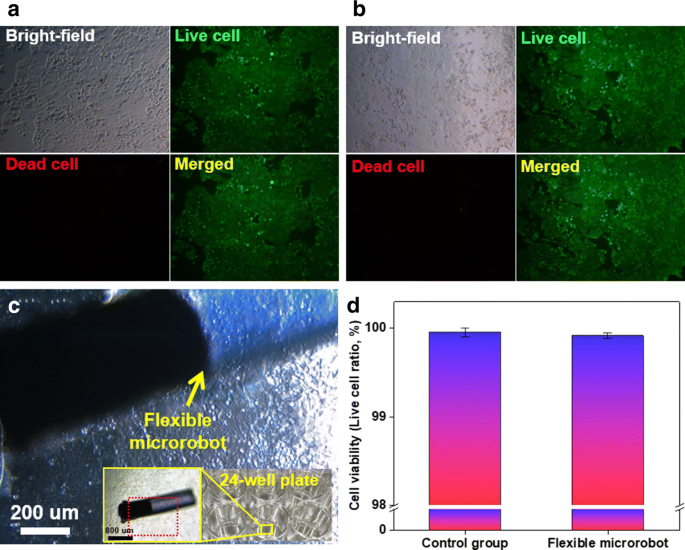
The biocompatibility test results. Bright-field and fluorescent images of HCT116 cells in wells a without flexible microrobots (control group) and b with flexible microrobots. c HCT116 cells around flexible microrobots. d Cell viabilities

Cell viability was assessed using a LIVE/DEAD Cell Imaging Kit (excitation wavelength 488 nm, emission wavelength 570 nm; Molecular Probes, Life Technologies Corp., USA) to stain live (green fluorescent signal) and dead (red fluorescent signal) cells. Cells cultured without robots (control cells) are shown in Fig. 10a, and cells cultured with microrobots in Fig. 10b, c. Figure 10d shows the cell viabilities, which were similar between the two groups. Thus, the robot is non-toxic.
Conclusion
We designed and fabricated, via replica-molding, a guidewire-based robot for use during PCI. A low-level magnetic field affords actuation; the robot is highly flexible, smaller than a coronary artery, and connected to a conventional guidewire. The robot is steered and controlled using a low-intensity, external magnetic fields (5–15 mT). Robot deformation is controlled using geometric parameters (length and diameter), magnetic steering (extent and direction), and the material properties. We used Euler–Bernoulli theory and an FEM to predict robot deformation. The experimental results were in good agreement with the simulated values, but not the mathematical data. The robot moved within a two-dimensional blood phantom featuring many branches. The robot was guided to desired locations and steered into branches at angles of 45 and 80º. Furthermore, the robot was not toxic to human cells, and can thus be used in vivo.
References
Kafash Hoshiar A, Le T, Amin F, Kim M, Yoon J (2017) A novel magnetic actuation scheme to disaggregate nanoparticles and enhance passage across the blood–brain barrier. Nanomaterials 8(1):3
Kafash Hoshiar A, Le T, Amin F, Kim M, Yoon J (2017) Studies of aggregated nanoparticles steering during magnetic-guided drug delivery in the blood vessels. J Magn Magn Mater 427:181–187
Amin F et al (2017) Osmotin-loaded magnetic nanoparticles with electromagnetic guidance for the treatment of Alzheimer’s disease. Nanoscale 9(30):10619–10632
Kim S, Qiu F, Kim S, Ghanbari A, Moon C, Zhang L et al (2013) Fabrication and characterization of magnetic microrobots for three-dimensional cell culture and targeted transportation. Adv Mater 25:5863–5868
Ullrich F, Bergeles C, Pokki J, Ergeneman O, Erni S, Chatzipirpiridis G et al (2013) Mobility experiments with microrobots for minimally invasive intraocular surgery: microrobot experiments for intraocular surgery. Invest Ophthalmol Vis Sci 54:2853–2863
Han J, Zhen J, Go G, Choi Y, Ko SY, Park JO, Park S (2016) Hybrid-actuating macrophage-based microrobots for active cancer therapy. Sci Rep 6:28717
Kim S, Lee S, Lee J, Nelson BJ, Zhang L, Choi H (2016) Fabrication and manipulation of ciliary microrobots with non-reciprocal magnetic actuation. Sci Rep 6:30713
Servant A, Qiu F, Mazza M, Kostarelos K, Nelson BJ (2015) Controlled in vivo swimming of a swarm of bacteria-like microrobotic flagella. Adv Mater 27(19):2981–2988
Zhang L, Abbott JJ, Dong L, Kratochvil BE, Bell D, Nelson BJ (2009) Artificial bacterial flagella: fabrication and magnetic control. Appl Phys Lett 94(6):064107
Abbott JJ, Peyer KE, Lagomarsino MC, Zhang L, Dong L, Kaliakatsos IK, Nelson BJ (2009) How should microrobots swim? Int J Robot Res 28(11–12):1434–1447
Nelson BJ, Kaliakatsos IK, Abbott JJ (2010) Microrobots for minimally invasive medicine. Annu Rev Biomed Eng 12:55–85
Peyer KE, Tottori S, Qiu F, Zhang L, Nelson BJ (2013) Magnetic helical micromachines. Chem Eur J 19(1):28–38
Fu Y, Liu H, Huang W, Wang S, Liang Z (2009) Steerable catheters in minimally invasive vascular surgery. Int J Med Robot Comput Assist Surg 5(4):381–391
Touma G, Ramsay D, Weaver J (2015) Chronic total occlusions—current techniques and future directions. IJC Heart Vasculature 7:28–39
Jeon S, Kafash Hoshiar A, Kim K, Lee S, Kim E, Lee S et al (2018) A magnetically controlled soft microrobot steering a guidewire in a three-dimensional phantom vascular network. soft robotics, On-line published
Kafash Hoshiar A, Jeon S, Kim K, Lee S, Kim JY, Choi H (2018) Steering algorithm for a flexible microrobot to enhance guidewire control in a coronary angioplasty application. Micromachines 9(12):617
Lee S, Lee S, Kim S, Yoon CH, Park HJ, Kim JY, Choi H (2018) Fabrication and characterization of a magnetic drilling actuator for navigation in a three-dimensional phantom vascular network. Sci Rep 8(1):3691
Houser RA, Bourne T (1998) U.S. Patent No. 5,833,604. Washington, DC: U.S. Patent and Trademark Office
Chatzipirpiridis G, Erne P, Ergeneman O, Pané S, Nelson BJ (2015). A magnetic force sensor on a catheter tip for minimally invasive surgery. In: Engineering in medicine and biology society (EMBC), 2015 37th annual international conference of the IEEE, pp 7970–7973
Krings T, Finney J, Niggemann P, Reinacher P, Lück N, Drexler A et al (2006) Magnetic versus manual guidewire manipulation in neuroradiology: in vitro results. Neuroradiology 48(6):394–401
Schiemann M, Killmann R, Kleen M, Abolmaali N, Finney J, Vogl TJ (2004) Vascular guide wire navigation with a magnetic guidance system: experimental results in a phantom. Radiology 232(2):475–481
Petruska AJ, Ruetz F, Hong A, Regli L, Sürücü O, Zemmar A, Nelson BJ (2016). Magnetic needle guidance for neurosurgery: initial design and proof of concept. In: Robotics and automation (ICRA), 2016 IEEE international conference on, pp 4392–4397
Muller L, Saeed M, Wilson MW, Hetts SW (2012) Remote control catheter navigation: options for guidance under MRI. J Cardiovasc Magn Reson 14(1):33
Lalande V, Gosselin FP, Vonthron M, Conan B, Tremblay C, Beaudoin G et al (2015) In vivo demonstration of magnetic guidewire steerability in a MRI system with additional gradient coils. Med Phys 42(2):969–976
Settecase F, Sussman MS, Wilson MW, Hetts S, Arenson RL, Malba V et al (2007) Magnetically-assisted remote control (MARC) steering of endovascular catheters for interventional MRI: a model for deflection and design implications. Med Phys 34(8):3135–3142
Haga Y, Esashi M (2000) Small diameter active catheter using shape memory alloy coils. IEEJ Trans Sens Micromachines 120(11):509–514
Clogenson HC, Dankelman J, van den Dobbelsteen JJ (2014) Steerable guidewire for magnetic resonance guided endovascular interventions. J Med Devices 8(2):021002
Zhang M, Wu J, Wang L, Xiao K, Wen W (2010) A simple method for fabricating multi-layer PDMS structures for 3D microfluidic chips. Lab Chip 10(9):1199–1203
Schuerle S, Erni S, Flink M, Kratochvil BE, Nelson BJ (2013) Three-dimensional magnetic manipulation of micro- and nanostructures for applications in life sciences. IEEE Trans Magn 49(1):321–330
Kratochvil BE, Kummer MP, Erni S, Borer R, Frutiger DR, Schürle S, Nelson BJ (2014). MiniMag: a hemispherical electromagnetic system for 5-DOF wireless micromanipulation. In: Experimental robotics. Springer, Berlin, pp 317–329
Kummer MP, Abbott JJ, Kratochvil BE, Borer R, Sengul A, Nelson BJ (2010) OctoMag: an electromagnetic system for 5-DOF wireless micromanipulation. IEEE Trans Rob 26(6):1006–1017
Kim JY, Jeon S, Lee J, Lee S, Lee J, Jeon BO et al (2018) A simple and rapid fabrication method for biodegradable drug-encapsulating microrobots using laser micromachining, and characterization thereof. Sens Actuators B Chem 266:276–287
Lee S, Kim S, Kim S, Kim JY, Moon C, Nelson BJ, Choi H (2018) A capsule-type microrobot with pick-and-drop motion for targeted drug and cell delivery. Adv Healthc Mater 7(9):1700985
Kim E, Yoo SJ, Kwon TH, Zhang L, Moon C, Choi H (2016) Nano-patterned SU-8 surface using nanosphere-lithography for enhanced neuronal cell growth. Nanotechnology 27(17):175303
Authors’ contributions
SJ and AKH carried out the simulation, the experiment and wrote the manuscript. SK and SL guided analysis data and reviewed the manuscript. EK cultured HCT116 cells and conducted biocompatibility test of microrobot. SL and KK designed and fabricated microrobots. JL conducted the experiment. JK and HC conceived of the study and wrote the manuscript. All authors read and approved the final manuscript.
Acknowledgements
The authors are grateful to all members of DGIST-ETH Microrobot Research Center and Bio-Micro Robotics Lab. for their sincere help and comments.
Competing interests
The authors declare that they have no competing interests.
Funding
Funding for this research was provided by the Korea Evaluation Institute of Industrial Technology (KEIT) funded by the Ministry of Trade, Industry & Energy (No. 10052980) and the Global Research Laboratory from the National Research Foundation of Korea (NRF) funded by the Ministry of Science and ICT (No. NRF 2017K1A1A2013237).
Publisher’s Note
Springer Nature remains neutral with regard to jurisdictional claims in published maps and institutional affiliations.
Author information
Authors and Affiliations
Corresponding author
Additional file
Additional file 1.
In vitro tracking of the a magnetically actuated flexible microrobot within a 2D phantom.
Rights and permissions
Open Access This article is distributed under the terms of the Creative Commons Attribution 4.0 International License (http://creativecommons.org/licenses/by/4.0/), which permits unrestricted use, distribution, and reproduction in any medium, provided you give appropriate credit to the original author(s) and the source, provide a link to the Creative Commons license, and indicate if changes were made.
About this article

Cite this article
Jeon, S., Hoshiar, A.K., Kim, S. et al. Improving guidewire-mediated steerability of a magnetically actuated flexible microrobot. Micro and Nano Syst Lett 6, 15 (2018). https://doi.org/10.1186/s40486-018-0077-y
Received:
Accepted:
Published:
DOI: https://doi.org/10.1186/s40486-018-0077-y