
Abstract
A new stepped septum-type waveguide circular polarizer (SST-CP) was developed to operate in the 230 GHz band for radio astronomy, especially submillimeter-band VLBI observations. For previously reported SST-CP models, the 230 GHz band is too high to achieve the design characteristics in manufactured devices because of unexpected machining errors. To realize a functional SST-CP that can operate in the submillimeter band, a new method was developed, in which the division surface is shifted from the top step of the septum to the second step from the top, and we simulated the expected machining error. The SST-CP using this method can compensate for specified machining errors and suppress serious deterioration. To verify the proposed method, several test pieces were manufactured, and their characteristics were measured using a VNA. These results indicated that the insertion losses were approximately 0.75 dB, and the input return losses and the crosstalk of the left- and right-hand circular polarization were greater than 20 dB at 220–245 GHz on 300 K. Moreover, a 230 GHz SST-CP was developed by the proposed method and installed in a 1.85-m radio telescope receiver systems, and then had used for scientific observations during one observation season without any problems. These achievements demonstrate the successful development of a 230 GHz SST-CP for radio astronomical observations. Furthermore, the proposed method can be applicable for observations in higher frequency bands, such as 345 GHz.
1 Introduction
In radio astronomy, very-long-baseline interferometry (VLBI) observations, which can achieve extremely fine angular resolution through the interference of several radio telescopes placed at very far from each other, are very important in most cases to observe extremely small astral bodies, such as active galactic nuclei (AGNs) and black hole shadows. To observe such bodies, radio astronomical observers have recently come to expect the realization of submillimeter VLBI observations at frequencies of 230 GHz or more through the cooperation of international astronomical organizations.
For VLBI observation, it is necessary to conform the received polarization direction for all VLBI telescopes; thus, left- or right-hand circular polarization (LHCP or RHCP) is generally used. However, most radio receivers have the sensitive for only either linear polarization (H-pol or V-pol) and thus need somewhat that convert the inputted circularly polarized wave to linear polarization.
To achieve this, a primitive methods using a quarter wavelength plate have been used widely. The quarter wavelength plate can convert dual circularly polarization to each linear polarization, and a subsequent radio receiver detects either converted wave as shown in Fig. 1a, or using orthogonal mode transducer (OMT), which separates then outputs the inputted dual linear polarization, two subsequent radio receivers detect both converted wave as shown in Fig. 1b.

Schematics of three major methods of receiving and recognizing the circular polarization wave
Using the waveguide circular polarizer (WG-CP) as shown in Fig. 1c is the simplest method, so that the various of WG-CP models have been developed [1–18]. The models in [1–10] are the WG-CP without stepped septum, and [11–18] are the stepped septum-type WG-CPs, which are hereafter simply referred to as SST-CP. Although most of the well-known WG-CPs have less fractional bandwidth (∼20%) than using quarter wavelength plate and OMT, the WG-CP works as a single component with lower insertion loss, thus it is easy to install into receivers. This is especially true for SST-CPs, so that SST-CPs are greatly advantageous for specified band observations, such as VLBI observations [12, 13].
Although SST-CPs have been commonly used in up to 45 GHz band, very few studies have reported the development and practical use of SST-CPs over 230 GHz [11]. The reasons why WG-CPs are not used at higher frequencies are considered to be as follows.
-
(1)
Most of the commonly used SST-CP design has a very thin septum for its waveguide [12–18]; for example, a H-band WG-CPs has a 1.5-mm septum for its square shaped input waveguide with dimensions of 28.5 mm × 28.5 mm. Thus, such SST-CPs cannot be simply scaled down without a loss of reliability, and new smaller models must be designed to have a very thick septum.
-
(2)
Even if models with a thick septum are successfully designed, the manufactured test pieces may have several very small hollow spaces on top of the septum, as shown in Fig. 2a. These spaces cause unexpected higher-mode resonance, ultimately greatly deteriorating the characteristics of the SST-CP.
Fig. 2 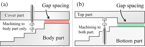
a Schematic of the four-step septum section of the conventional model and b the proposed gap space shifted model

This paper introduces an improved SST-CP model, which has a septum with a very large thickness of 0.20 mm for a square input waveguide with dimensions of 0.82 mm × 0.82 mm and suppresses the deterioration caused by the gap spacing on the septum. In this new model, the division surface was shifted from the top of septum to one lower step, as shown in Fig. 2b. The model was then optimized using numerical simulations with various shapes and dimensions of the gap spacing and determined the expected acceptable deterioration to suppress unexpected resonances. Using the proposed model, we developed a SST-CP that can be operated at frequency bands over 230 GHz with a practical machining performance. In section 2, we described the general mechanism of SST-CPs. The details of the designing are described in sections 3 and 4, the measurement results are in section 5, and the astronomical observation application is described in section 6.
2 General Mechanism of Septum-Type Waveguide Circular Polarizer
The SST-CP is a well-known waveguide circuit, and various models have been proposed. Models with four steps in the septum and square waveguides are the most commonly used [11–18]. Their mechanism of separating RHCP and LHCP input waves is briefly described in the following [13].
The radio waves input from the feed horn are first polarized orthogonally and then transferred to the septum in the two fundamental propagation modes TE10 (H-pol) and TE01 (V-pol). The septum is a step-like metal wall located in the center of the square waveguide, dividing it into two equal sections.
The waves that reach the septum cause the gradual mode transformation of the H- and V-pol waves, as shown in Fig. 3. The H-pol waves are simply divided to half, and the V-pol waves are transformed into the fundamental mode wave of the output rectangular waveguide with a 90° and –90° phase shift for outputs on the right and left sides.

Schematics of the propagation mode transition of input TE10 and TE01 modes from the input to the end of the septum. The colored arrows are the electric field vectors calculated by the simulator HFSS (ANSYS), and the solid gray arrows show the trends of the vectors
The circularly polarized waves are composed of two orthogonal linearly polarized waves of equal amplitude with a 90° phase difference. Thus, the combined electrical field direction is rotated clockwise or counterclockwise. For radio astronomical equipment, the clockwise and counter-clockwise waves observed by receivers are referred to as RHCP and LHCP, respectively.
When a circularly polarized wave is input into a SST-CP, and if its V-pol component lagged from H-pol component by 90°, an additional 90° delay for V-pol would be caused at the left side of septum, so that the input waves are canceled by virtue of being antiphase with the H-pol component. However, at the right side of septum the lagged V-pol would be proceeded by 90° in contrast, and then doubled as a result of the coherence with H-pol component. Therefore, the input waves of V-pol lagged should be output from the right side only, and in contrast, the proceeded V-pol waves should be output from the left side only.
To explain a general feature of SST-CPs, the cross-polarization (X-pol) frequency characteristics of a conventional 6–9 GHz SST-CP, which was designed for a C-X band VLBI observation receiver, are shown in Fig. 4a. The X-pol or crosstalk level is defined as the magnitude of confused opposite polarization signals. A very strong X-pol degradation at ∼7.5 GHz is a common nature of SST-CPs; for example, Yonekura et al. (2016) [12] shows the similar degradations on their WG-CP. This nature is likely the effect of a higher-mode resonance of transmuted TE11 near the first step of the septum as shown in Fig. 4b [19, 20], and this resonance is inevitable according to Cresci et al. [14]. The higher frequency band than the TE11 resonance is an unstable frequency range in which the higher-mode resonances are easily induced. In Fig. 4a, there are five strong resonance peaks at >7.6 GHz. Most of these resonance peaks are seemed to be caused by the mismatch of the mode transformation on the septum. Also, these can be shifted, suppressed, and sometimes removed by optimizing the septum step lengths and heights; however, it is very difficult to remove all of them, and achieving it in manufactured devices is much more impractical.

a Simulated X-pol frequency characteristics of a 6–9 GHz WG-CP. b Plot of the magnitudes of simulated electric fields on three specific planes at 7.56 GHz, where transmuted TE11 mode resonance occurs, and electric field vectors in the xz plane where y is approximately the center of considered resonance
In contrast to the higher band, the frequency band lower than the TE11 resonance is known to be a very stable band. Generally, the conventional SST-CPs are designed to be used only this band, so that their fractional bandwidth are limited to ∼20%. The proposed 230 GHz SST-CP was also designed in this stable band, because VLBI observation requires a very stable receiver.
3 Design of 230 GHz Septum-Type Waveguide Circular Polarizer
In this study, a 230 GHz SST-CP with two types of solution models was designed using the three-dimensional finite element method (3D-FEM) electromagnetic field solver HFSS (ANSYS). Figure 5a shows the simulated single SST-CP model. Port 1 is a square input port that excites pure V- and H-pol waves. Ports 2 and 3 on the right and left sides are the RHCP and LHCP output ports, respectively. With the single model, the V- and H-pol input return losses (S 11), the transition between the two output ports (output port isolation, S 23), and the accelerated or delayed phase of inputted V-pol were optimized. Furthermore, the transition from the input port to each output port for each orthogonal mode (S 21, S 31) can be estimated. However, this transition is not the insertion loss of the circularly polarized wave.

Schematics of the 230 GHz SST-CP simulation 3D-FEM models. a Single SST-CP solution model. b Mirror duplicated solution model
Thus, an alternative model called the mirror model was also simulated, as shown in Fig. 5b. This model is composed of the single model and a mirror duplicate connected directly at the square input port. With this model, the insertion losses of circular polarization and X-pol were optimized. The insertion losses of S 31 from port 1 to port 3 and S 42 from port 2 to port 4 can be treated as square the circularly polarization insertion loss of single model. This is because at one of the SST-CPs in the mirror model, the input wave from the output port of the single model is converted to a predefined circularly polarized wave and the other SST-CP divides the generated circular polarization. Additionally, the transmission levels S 41 from port 1 to port 4 and S 32 from port 2 to port 3 represent twice the X-pol of single model, because there is double the possibility of inducing X-pol in each septum section. Thus, the X-pol of the single model is almost –3 dB (half) from S 41, S 32. These characteristics can also be measured using a vector network analyzer (VNA) [16]; thus, the simulated design can be verified with very high accuracy. This is an important advantage in the adaptation of the proposed design method.
Figure 6 shows the details of the septum. The septum is one of the main features defining a septum-type circular polarizer, and various septum models have been proposed. However, the design of the 230 GHz SST-CP requires a simple septum structure to suppress machining error; thus, four simple rectangular steps were adopted, and the septum thickness was defined as greater than 20% of the size of the square input waveguide to reduce manufacturing error. To determine all dimensions of the steps shown in Fig. 6b, the two models described above were optimized alternately and repeatedly. This is because if the parameters are determined using only one model, the uncalculated characteristics of another model are neglected, typically leading to the deterioration of the waveguide characteristics.

a Top and b side views of the septum of the 230 GHz SST-CP
The simulation results of the single and mirror models are shown in Fig. 7a, b, respectively. In these graphs, the magnitude of each S-parameter is plotted against the frequency. In Fig. 7a, S11-V and S11-H represent the input port return losses for V- and H-pol waves, respectively; S 22 and S 33 are the return losses for the LHCP and RHCP output ports, respectively; and S 23 is the output port isolation shown in Fig. 5a. Additionally, in Fig. 7b, S 31 is the transmission level of the RHCP in the mirror model; S 11 is the return loss of every input port; and S 41 is the X-pol.

Simulated performance of the a single and b mirror models of the 230 GHz SST-CP
According to these results, the designed model has a return loss of greater than 20 dB on every port at 218–247 GHz (S 11, S 22, and S 33), and the output port isolation S 23 is greater than 37 dB, also the X-pol S 41 is greater than 20 dB at 213–247 GHz. Additionally, there is significant performance degradation near 249 GHz, which is the effect of TE11 mode resonance, as explained by Fig. 4. This indicates that the described performance under 247 GHz is in the stable band of SST-CP. Furthermore, because of this very good design performance, even if an unexpected deterioration is caused by manufacturing error, the manufactured SST-CP could remain functional.
4 Suppressing of the Deterioration by Expected Manufacturing Errors
The manufacturing errors and also assembling alignment errors often lead the very serious deterioration of waveguide circuit characteristics, and the WG-CP at higher band such as 230 GHz is one of the most sensitive case. We had studied what prevents the 230 GHz WG-CP from practical using with several test pieces, then we found that the space on the top of septum might be a major suspect. In the almost past models, the waveguide circuit is divided into two pieces (the body and cover part) on the top surface of septum. On such structure, the spaces around top of septum due to the defective touch of two pieces are inevitable problem for very precise components.
Manufacturing and assembling alignment errors often lead to the very serious deterioration of the waveguide circuit characteristics, and the operation of SST-CPs in higher frequency bands, such as the 230 GHz band, is one of the most sensitive cases. The features that are most likely to prevent the practical use of the 230 GHz SST-CP were determined using several test pieces, and it was found that the space above the septum is a major factor. In most previously developed models, the waveguide circuit is divided into two parts, the body and the cover, on the top surface of the septum. In such a structure, the formation of spaces around the top of the septum by the unintended contact of the two pieces is an inevitable problem for very precise components.
To determine how this space leads to the deterioration of the waveguide characteristics, the verification model shown in Fig. 8 was simulated to estimate the influence of such spaces. In this simulation, two dimensional parameters sy and sz were defined, and the S-parameters were calculated while varying these parameters. The parameters sy and sz are the length and thickness of the space above the septum, respectively. Figures 9 and 10 show the simulation results for the deterioration of the V-pol input return loss of the single model and that of the X-pol of the mirror model, respectively. Each graph in the figures shows the magnitude of the S-parameters plotted against the frequency. These simulation results were obtained with one parameter varying and the other held fixed.

Schematics of one of the verification simulation models

Calculation results for the deterioration of the 230 GHz SST-CP V-pol input return loss in the single model. a The thickness sz was varied with the length sy fixed at 1.2 mm. b The length sy was varied with the thickness sz fixed at 4 μm

Calculation results for the deterioration of the X-pol level in the mirror model. a The thickness sz was varied with the length sy fixed at 1.2 mm. b The length sy was varied with the thickness sz fixed at 4 μm
As shown in Fig. 9a, there were large deteriorations in the simulation, especially at 220–245 GHz, and return losses were degraded worse than 20 dB for sz > 4 μm. The deterioration with varying sy showed a periodic pattern with a period of approximately 0.6 mm, as shown by the black and red lines in Fig. 9b; this periodicity may depend on the wavelength. Additionally, when sy was relatively low, the deterioration was larger than when sy was high. The results of X-pol shown in Fig. 10b indicate that the X-pol return losses show the same tendencies; however, no clear periodic pattern was observed. Furthermore, the TE11 mode resonance frequency was fixed, but its magnitude varied somewhat with varying sy.
Therefore, it was concluded that the thickness of the space above the septum has a large influence on the deterioration of manufactured SST-CPs, perhaps more than any other factor. Additionally, a new method of manufacturing SST-CPs is required to suppress this deterioration. This is because it is too hard to realize a nearly zero sz while controlling sy such that it falls on the desired point in the periodical deterioration curve. It is very difficult to achieve a reasonable and stable SST-CP with previously developed models.
Next, it was determined why spaces above the septum lead to such serious problems. One hypothesis is that the space above the septum acts as an additional step in the septum. When designing the septum, it is necessary to determine the number of steps. However, when the unintended space above the septum acts as an additional step, the designed septum characteristics, such as the impedance, differ from the actual characteristics of the manufactured septum, especially when the space length is low (e.g., sy = 0.3 mm). Additionally, the electric field becomes centered around the top of the septum, increasing the magnitude of this effect.
On the grounds of the above considerations and hypothesis, the dividing method was altered in the present study. An alternative way of dividing the second step from the top was devised, as shown in Fig. 2b. In this method, the space above the septum does not act as an additional step, and the electric fields are not concentrated; thus, it was expected that the influence of the space was much less than that in conventional designs. To verify this, the deterioration of the shifted spaces was simulated using the shifted space verification model shown in Fig. 11, and the simulation results are shown in Figs. 12 and 13. In this model, the parameters sy2 and sz2 represent the length and thickness of the gap spacing, respectively. The conditions of these graphs are the same as those in Figs. 9 and 10, respectively.

Schematics of the space shifted verification simulation models

Calculation results for the deterioration of V-pol input return loss of the shifted space single model. a The thickness sz2 was varied with the length sy2 fixed at 1.2 mm. b The length sy2 was varied with the thickness sz2 fixed at 4 μm

Calculation results for the deterioration of the X-pol level of the shifted space mirror model. a The thickness sz2 was varied with the length sy2 fixed at 1.2 mm. b The length sy2 was varied with the thickness sz2 fixed at 4 μm
A comparison of these results clearly indicates that the shifted space model suppresses deterioration and is especially resilient against increasing space thickness sz2. Although the return loss deterioration obtain when varying sy2 was not stable and showed a periodic pattern, the shifted space model was very effective in stabilizing the X-pol; as shown in Fig. 13b, the X-pol remained over 30 dB at 220–245 GHz for all considered sy2 values. Additionally, in contrast to the behavior in the stable band, the TE11 mode resonance effect was not changed at all.
5 Manufacturing and Measurement
To confirm the actual characteristics of the proposed method, we manufactured the test pieces shown in Fig. 14, and then measured their frequency characteristics using VNA. The measurement was performed for the mirror model configuration only; this is because the waveguide type VNAs can only test with rectangular shaped inputs/outputs, so that it was difficult to input the certainly circular polarized or V/H-polarized test signals for the single configuration. However, from the measured results and additional fitting simulation, we could estimate the characteristics of the single configuration; thus, it was enough to confirm the effect of proposed method.

Photograph of a manufactured 230 GHz band SST-CP. There are milled waveguide circuits divided on the surface of the second step from the top of the septum on both half blocks. The part on the left is the bottom part and includes the first to fourth septum steps, and the part on the right is the cover and includes the end wall of the fourth step
The measured return loss and X-pol performances on mirror configuration are shown in Fig. 15, and the measured insertion loss is shown in Fig. 16. The measurement was performed using the WR-5.1 extender module from 200 to 220 GHz and the WR-3.4 module from 220 to 250 GHz with its noise floor of −25 dB, so that the stabilities of two frequency band of the obtained data were different, with the WR-5.1 data showing better stability. Figures 15 and 16 show that the manufactured SST-CPs have the return loss and X-pol performance of greater than 20 dB, and the insertion loss is smaller than 1.5 dB for two SST-CPs at 220∼247 GHz. The best fitting simulation result indicates that the actual gap spacing on septum are estimated to be sy2 = 0.75 mm and sz2 = 12 μm. Furthermore, the frequency of the TE11 resonance corresponds exactly to the design; however, its magnitude is clearly small. Why this attenuation causes is unknown in the current situation.

Measured return loss and X-pol performance of 230 GHz SST-CP. a The return loss and b the X-pol of mirror configuration. In both figures, the red and green dots show the measured data, the black solid line is the performance on original design, and the black dashed line is the best fitting simulation result where sz2 = 0.75 mm and sy2 = 12 μm

Measured insertion loss of 230 GHz SST-CP. The blue dots show the measured insertion loss subtracted the loss of the measurement tools. The solid line and the dashed line are the original and best fitting simulation results, respectively. In these simulations, the surface roughness of the waveguides was not considered, so that these simulation results are underestimated
These results indicate that the performance of the SST-CP manufactured with the proposed method would not be deteriorated so much even if the gap spacing reaches the maximum allowable gap spacing of the conventional model. Furthermore, the fact of the TE11 resonance frequency corresponds to that in the design indicates that the manufacturing of the 230 GHz SST-CP was achieved with very good overall accuracy. These achievements demonstrate the successful realization of a 230 GHz SST-CP and indicate that the proposed method in this paper can be applicable for the higher frequency bands.
6 Installation of 230 GHz Septum-Type Waveguide Circular Polarizer in 1.85-m Telescope
The developed 230 GHz SST-CP was installed in the 1.85-m telescope of Osaka Prefecture University (OPU). This millimeter/submillimeter Cassegrain Nasmyth reflector radio telescope with a main reflector of 1.85 m in diameter was developed in a previous study by a radio astronomy group of OPU. It was installed in the Nobeyama Radio Observatory of the National Astronomical Observatory of Japan (NAOJ/NRO) in 2007 and has been used to simultaneously observe the J = 2–1 spectral lines of three CO isotopes by using the sideband separation receiver [21–23]. Thus, this telescope is a reasonable environment to demonstrate the performance of the proposed 230 GHz SST-CP receiver.
Figure 17 shows a photograph of the proposed 230 GHz SST-CP receiver installed in the 1.85-m telescope. This 4 K cooling receiver contains the developed SST-CP, two sideband separation waveguide filters for LHCP and RHCP, and a total of four SIS mixers. Figure 18 shows the chopper-wheel calibrated spectrum of the 48 times 20 s integrated observation toward a specific Orion KL region (RA = 05h 35 m 14s.5, Dec = –05° 22′ 29.6〞) using the 1.85-m telescope containing the proposed SST-CP receiver and obtained using a 0–2 GHz digital fast Fourier transform spectrometer. This result indicates that the proposed receiver can be used for radio astronomical observations.

Photograph of the proposed 230 GHz SST-CP 4 K cooling receiver which was installed in a 1.85-m telescope

Chopper-wheel calibrated spectrum of the observation toward an Orion KL region using the 1.85-m telescope with proposed 230 GHz SST-CP receiver
Based on these achievements, the proposed shifted space submillimeter SST-CP has been or would be installed into several other telescope receivers, including the NANTEN2 Observatory 4-m telescope of Nagoya University in the 110 GHz band, and the Green Land Telescope (GLT) of the Academia Sinica Institute of Astronomy and Astrophysics (ASIAA), which is the dedicated telescope for submillimeter VLBI observations of black hole shadows [24].
7 Conclusion
In this study, a SST-CP that is operational in the 230 GHz band for use in radio astronomy, especially submillimeter-band VLBI observations, was developed. This device separates the input dual circularly polarized waves into LHCP and RHCP outputs at 230 GHz, a frequency band too high for previously proposed models to achieve their design characteristics because of machining errors.
A novel method involving shifting the division surface from the top step of the septum to the second step from the top was shown to be able to compensate for the expected machining errors and suppress serious deterioration. The manufactured test pieces were measured using a VNA. The results indicate that there is a space of approximately 12 μm in height above the second step of the septum; however, the measured characteristics remained sufficient for radio astronomical observations. Moreover, the 230 GHz SST-CP was installed in the OPU 1.85-m radio telescope and used for actual scientific observations during one observation season.
The above achievements demonstrate the successful development and realization of a reasonable 230 GHz SST-CP and the successful practical use on radio astronomical line spectra observation. Furthermore, from the fact that the GLT of ASIAA has adopted the proposed SST-CP for submillimeter VLBI observation receiver, submillimeter-band VLBI observation at 230 GHz has been made possible with the proposed 230 GHz SST-CP.
References
S-W. Wang, C-H. Chien, C-L. Wang, and R-B. Wu, “A Circular Polarizer Designed With a Dielectric Septum Loading”, IEEE Trans. Microw. Theory Tech., vol.52 No.7, pp1719-1723, Jul. 2004.
G. Bertin, B. Piovano, L. Accatino, and M. Mongiardo, “Full-Wave Design and Optimization of Circular Waveguide Polarizers with Elliptical Irises”, IEEE Trans. Microw. Theory Tech., vol.50 No.4, pp1077-1083, Apr. 2002.
J. Bornemann, S. Amari, J. Uher and R. Vahldieck, “Analysis and Design of Circular Ridged Waveguide Components”, IEEE Trans. Microw. Theory Tech., vol.47 No.3, pp330-335, Mar. 1999.
R. Behe and P. Brachat, “Compact Duplexer-Polarizer with Semicircular Waveguide”, IEEE Antennas Propag., Vol. 39, No.8, pp142-14, Aug. 1991
B. Subbarao and V. F. Fusco, “Compact Coaxial-Fed CP Polarizer”, IEEE Antennas and Wireless Propag. Letters, Vol. 3, pp 145-147, 2004
N. Yoneda, M. Miyazaki, H. Matsumura, and M. Yamato, “A Design of Novel Grooved Circular Waveguide Polarizers”, IEEE Trans. Microw. Theory Tech., vol.48, No.12, pp2446-2552, Dec. 2000.
C. Chang, S. Church, S. Tantawi, P. Voll, M. Sieth, and K. Devaraj, “Theory and experiment of a compact waveguide dual circular polarizer”, Progress In Electromagnetics Research, Vol. 131, 211-225, 2012
C. Chang, S. Tantawi, S. Church, J. Neilson, and P. V. Larkoski, “Novel compact waveguide dual circular polarizer”, Progress In Electromagnetics Research, Vol. 136, 1-16, 2013
L. Martinez-Lopez, J. Rodrigez-Cuevas, J. I. Martinez-Lopez, and A. E. Martynyuk, “A Multilayer Circular Polarizer Based on Bisec”, IEEE Antennas and Wireless Propag. Letters, Vol. 13, pp 153-156, 2014
G. Virone, R. Tascone, M. Baralis, O. A. Peverini, A. Olivieri and R. Orta, “A Novel Design Tool for Waveguide Polarizers”, IEEE Trans. Microw. Theory Tech., vol.53 No.3, pp888-894, Mar. 2005.
C. A. Leal-Sevillano, K. B. Cooper, J. A. Ruiz-Cruz, J. R. Montejo-Garai and J. M. Rebollar, “A 225 GHz Circular Polarization Waveguide Duplexer Based on a Septum Orthomode Transducer Polarizer”, IEEE Trans. THz Sci. Tech. vol.3, No.5, pp574-583, Sep. 2013
Y. Yonekura, et al., “The Hitachi and Takahagi 32 m radio telescopes: Upgrade of the antennas from satellite communication to radio telescopes”, Publ. Astron. Soc. Japan 68(5), 74(1-31), August 2013
M. Kaiden, K. Kimura, H. Ogawa, T. Kasuga, M. Tsuboi, and Y. Murata, “Septum Polarizer for Ka-Band H-Shaped Rotary Joint”, J Infrared Milli Terahz Waves (2009) 30:727–737
L. Cresci, L. Ciappi, R. Nesti, F. Palagi and D. Panella, “C-band septum polarizer design”. Arcetri Technical Report, n. 6, 2002
J. Bornemann and V. A. Labay, “Ridge Waveguide Polarizer with Finite and Stepped-Thickness Septum”, IEEE Trans. Microw. Theory Tech., vol.43 No.8, pp1782-1787, Aug. 1995.
N. C. Albertsen and P. Skov-Madsen, “A Compact Septum Polarizer”, IEEE Trans. Microw. Theory Tech., vol.31 No.8, pp654-660, Aug. 1983.
Marc J. Franco, “A High-Performance Dual-Mode Feed Horn for Parabolic Reflectors with a SteppedSeptum Polarizer in a Circular Waveguide”, IEEE Antennas Propagation Magazine, Vol. 53, No.3, pp142-14, June 2011
Ming Hui Chen, and G. N. Tsandoulas, “A Wide-Band Square-Waveguide Array Polarizer”, IEEE Trans. on Antenna and Propagation, react-text: 53 Vol. 21, No. 3, pp389-391, /react-text react-text: 57 June. 1973 /react-text
N. Boukli-Hacene, J. Sombrin, and A. Papiernik, “Approximation by Gegenbauer polynomials in the study of arectangular ridged waveguide. Application to the analysis of a waveguide septum polarizer”, Int. J. Numer. Model. 2003; 16:299–318
W. J. R. hoefer and M. N. Burton,” Closed-Form Expressions for the Parameters of Finned and Ridged Waveguides”, IEEE Trans. Microw. Theory Tech., vol.30 No.12, pp2190-2194, Dec. 1982
T. Onishi et al.,“A 1.85-m mm-submm Telescope for Large-Scale Molecular Gas Surveys in 12CO, 13CO, and C18O (J = 2–1)”, Publ. Astron. Soc. Japan 65(4), 78(1-13), August 2013
A. Nishimura et al., “Revealing the physical properties of molecular gas in orion with a large-scale survey in J = 2-1 lines of 12CO, 13CO, and C18O”, ApJ Supplement Series, 216 : 18 (24pp), 2015
T. Shimoikura et al., “Molecular clumps and infrared clusters in the S247, S252, and BFS52 regions”, ApJ 768 : 72 (27pp), 2013
M. Inoue et al., “Greenland telescope project: Direct confirmation of black hole with sub-millimeter VLBI”, Radio Sci., 49, 564–571, 2014
Acknowledgements
The authors would like to thank Satoshi Ochiai and Akifumi Kasamatsu of the National Institute of Information and Communications Technology (NICT) and Kenichi Kikuchi of the National Astronomical Observatory of Japan (NAOJ) for measuring the WG-CP with a VNA at NICT. We are also very grateful to Masanori Ishino of Kawashima Manufacturing Co., Ltd. (KMCO) for conducting the high-precision machining of the SST-CP.
Additionally, we would like to thank all of those on the 1.85-m telescope team for installing and operating the developed FSF receiver to verify its performance. Further thanks go to Shinichiro Asayama for supporting to design and analyze WG-CP. This work was financially supported by JSPS KAKENHI (Grant Nos. 22244014 and 26247026), and the Toray Science Foundation.
Author information
Authors and Affiliations
Corresponding author
Rights and permissions
Open Access This article is distributed under the terms of the Creative Commons Attribution 4.0 International License (http://creativecommons.org/licenses/by/4.0/), which permits unrestricted use, distribution, and reproduction in any medium, provided you give appropriate credit to the original author(s) and the source, provide a link to the Creative Commons license, and indicate if changes were made.
About this article

Cite this article
Hasegawa, Y., Harada, R., Tokuda, K. et al. A New Approach to Suppress the Effect of Machining Error for Waveguide Septum Circular Polarizer at 230 GHz Band in Radio Astronomy. J Infrared Milli Terahz Waves 38, 638–652 (2017). https://doi.org/10.1007/s10762-017-0364-3
Received:
Accepted:
Published:
Issue Date:
DOI: https://doi.org/10.1007/s10762-017-0364-3