
Abstract
In this paper, a theoretical model was proposed to stress analysis and calculate the critical fluid pressure path corresponding to rupture instability in hydro-mechanical deep drawing (HMDD) of hemi-prolate spheroid (HPS) cups. This model is based on Barlat and Lian yield criterion and maximum drawing force condition was utilized to rupture instability analysis. The effects of material and process parameters were investigated on critical fluid pressure path. The results demonstrated that maximum permissible fluid pressure is increased by enhancement of sheet thickness, strain hardening exponent, anisotropy and reduction of friction coefficient. Decrease the difference between semi-major and semi-minor axis of the hemi-prolate spheroid, enlarges safe zone. Finally, a serial of HMDD experiments were accomplished to verify the theoretical critical fluid pressure path. Theoretical results agree well with experimental data.


Abbreviations
- a :
-
Barlat–Lian yield function constant
- A :
-
Semi-major axis of hemi-prolate spheroid
- b :
-
Current radius of flange
- b 0 :
-
Radius of initial blank
- B :
-
Semi-minor axis of hemi-prolate spheroid
- c :
-
Barlat–Lian yield function constant
- F f :
-
Friction force
- F p :
-
Punch force
- h :
-
Barlat–Lian yield function constant
- H :
-
Current height of cup
- K :
-
Material strength coefficient
- k 1, k 2 :
-
Barlat–Lian yield function constant
- m:
-
Barlat–Lian yield function exponent
- n :
-
Strain hardening exponent
- P :
-
Fluid pressure
- P cr :
-
Critical fluid pressure
- \(\bar{P}\) :
-
Dimensionless critical fluid pressure
- r :
-
Current radius of element
- \(r_{0}^{\text{I}} , \;r_{0}^{\text{II}}\) :
-
Initial radius of element in zone I and zone II, respectively
- R 0, R 45, R 90 :
-
Anisotropy coefficient
- R :
-
Normal anisotropy of sheet
- r d :
-
Die radius
- t :
-
Sheet thickness
- (x, y):
-
Coordinate of points on punch surface
- (x 0, y 0):
-
Coordinate of the border point zone II and zone III
- α :
-
Angle between normal line of the punch surface at (x 0, y 0) and x-direction
- ω :
-
Angle of Inclination of a tangent line at (x 0, y 0)
- ρ :
-
Curvature radius of zone II
- \(\rho_{\text{cr}}\) :
-
Critical curvature radius of zone II
- \(\bar{\sigma }\) :
-
Effective stress
- \(\sigma_{r} , \sigma_{\theta }\) :
-
Radial, circumferential stress components
- \(\sigma_{1} , \;\sigma_{2}\) :
-
Principal stress components
- \(\bar{\varepsilon }\) :
-
Effective strain
- \(\varepsilon_{r} , \;\varepsilon_{\theta } , \;\varepsilon_{t}\) :
-
Radial, circumferential and thickness strain components
- \(\varepsilon_{1}, \;\varepsilon_{2} , \;\varepsilon_{3}\) :
-
Principal strain components
- γ :
-
The ratio of circumferential stress to radial stress
- μ :
-
Friction coefficient
- λ :
-
Plastic multiplier
- φ :
-
Angle of sheet element at zone II
References
Zhang SH, Danckert J (1998) Development of hydromechanical deep drawing. Mater Process Technol 83:14–25
Tirosh J, Yossifon S, Eshel R, Betzer A (1977) Hydroforming process of uniform wall thickness products. ASME J Eng Ind 99:685–691
Yossifon S, Tirosh J, Kochavi E (1984) On suppression of plastic buckling in hydroforming processes. Int J Mech Sci 26:389–402
Yossifon S, Tirosh J (1985) Rupture instability in hydroforming deep-drawing process. Int J Mech Sci 27:559–570
Yossifon S, Tirosh J (1988) On the permissible fluid-pressure path in hydroforming deep drawing processes—analysis of failures and experiment. Trans ASME J Eng Ind 110:146–152
Lo SW, Hsu TC, Wilson WRD (1992) An analysis of the hemisphere punch hydroforming process. J Mater Process Technol 37:225–239
Fazli A, Dariani BM (2006) Theoretical and experimental analysis of the axisymmetric hydromechanical deep drawing process. Proc Inst Mech Eng B J Eng Manuf 220:1429–1437
Azodi HD, Naeini HM, Parsa MH et al (2008) Analysis of rupture instability in the hydromechanical deep drawing of cylindrical cups. Int J Adv Manuf Technol 39:734–743
Bagherzadeh S, Mollaei-Dariani B, Malekzadeh K (2012) Theoretical study on hydro-mechanical deep drawing process of bimetallic sheets and experimental observations. J Mater Process Technol 212:1840–1849
Chen Y, Liu W, Xu Y, Yuan S (2015) Analysis and experiment on wrinkling suppression for hydroforming of curved surface shell. Int J of Mech Sci 104:112–125
Jalil A, Hoseinpour-Gollo M, Sheikhi MM, Seyedkashi SMH (2015) Process analysis of hydrodynamic deep drawing of cone cups assisted by radial pressure. Proc Inst Mech Eng Part B J Eng Manuf. doi:10.1177/0954405415612325
Jalil A, Hoseinpour-Gollo M, Sheikhi MM, Seyedkashi SMH (2016) Hydrodynamic deep drawing of double layered conical cups. Trans Nonferrous Met Soc China 26:237–247
Anil Kumar A, Satapathy S, Ravi Kumar D (2010) Effect of Sheet thickness and punch roughness on formability of sheets in hydro-mechanical deep drawing. J Mater Eng Perform 19:1150–1160
Xin L, Yong-chao X, Shi-jian Y (2011) Hydro-forming of aluminum alloy complex-shaped components. Trans Nonferrous Met Soc China 21:417–422
Gorji A, Alavi-Hashemi H, Bakhshi-Jooybari M, Nourouzi S, Hosseinipour SJ (2011) Investigation of hydrodynamic deep drawing for conical–cylindrical cups. Int J Adv Manuf Technol 56:915–927
Meng B, Wan M, Yuan S, Xudong X, Liu J, Huang Z (2013) Influence of cavity pressure on hydrodynamic deep drawing of aluminum alloy rectangular box with wide flange. Int J Mech Sci 77:217–226
Bagherzadeh S, Mirnia MJ, Mollaei Dariani B (2015) Numerical and experimental investigations of hydro-mechanical deep drawing process of laminated aluminum/steel sheets. J Manuf Process 18:131–140
Hashemi A, Hoseinpour-Gollo M, Seyedkashi SMH (2015) Study of Al/St laminated sheet and constituent layers in radial pressure assisted hydrodynamic deep drawing. Mater Manuf Process. doi:10.1080/10426914.2015.1127947
Hashemi A, Hoseinpour-Gollo M, Seyedkashi SMH (2016) Bimetal cup hydroforming of Al/St and Cu/St composites: adaptive finite element analysis and experimental study. J Mech Sci Technol 30:2217–2224
Zhang R, Lang L, Zafar R, Lin L, Zhang W (2016) Investigation into thinning and spring back of multilayer metal forming using hydro-mechanical deep drawing (HMDD)for lightweight parts. Int J Adv Manuf Technol. doi:10.1007/s00170-015-7415-5
Barlat F, Lian J (1989) Plastic behavior and stretchability of sheet metals. Part I. A yield function for orthotropic sheets under plane stress conditions. Int J Plast 5:51–66
Burden R, Douglas Faires J (2010) Numerical methods, 9th edn. Brooks/Cole, Boston, pp 71–73
Kleemola HJ, Kumpulainen JO (1980) Factors influencing the FLD. Influence of sheet thickness. J Mech Work Technol 3:303–311
Beer F, Johnston R, Mazurek D, Cornwell P, Eisenberg E (2010) Vector mechanics for engineers: statics & dynamics, 9th edn. McGraw-Hill, New York, pp 218–281
Author information
Authors and Affiliations
Corresponding author
Additional information
Technical Editor: Márcio Bacci da Silva.
Appendix: The proofs of geometrical relations
Appendix: The proofs of geometrical relations
-
(a)
Calculation of b, \(r_{0}^{\text{I}}\) and \(r_{0}^{\text{II}}\):
Volume of zone I:
$$V_{\text{I}} = \pi \left[ {b^{2} - \left( {x_{0} + \left( {\rho + t} \right)\cos \alpha } \right)^{2} } \right]\,t$$(41)Volume of zone II:
From the Pappus–Guldinus theorem [24], the area of a surface of revolution is equal to:
$$S = 2\pi L\bar{r}$$(42)where L and \(\bar{r}\) are the length of the generating curve and the distance of the centroid of the curve from axis of revolution, respectively. As shown in Fig. 18a, the value of L for zone II is:
$$L = \widehat{AB} = \left( {\rho + t} \right)\left( {\frac{\pi }{2} - \alpha } \right)$$(43)Fig. 18 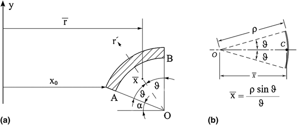
a Generating curve of zone II and its centroid position. b Centroid of a circular arc
According to Fig. 18b and using trigonometric relations, the distance of the centroid of the arc \(\widehat{AB}\) from the y-axis (\(\bar{r}\)) is determined through the following relation:
$$\bar{r} = x_{0} + \left( {\rho + t} \right)\cos \alpha - \frac{{\left( {\rho + t} \right)\sin \left( { \frac{\pi }{4} - \frac{\alpha }{2} } \right)}}{{ \frac{\pi }{4} - \frac{\alpha }{2} }}\cos \left( { \frac{\pi }{4} + \frac{\alpha }{2} } \right)$$(44)Substituting Eqs. (43) and (44) into Eq. (42), the surface of the product in zone II can be calculated as follows:
$$\begin{aligned}S^{\text{II}}& = 2\pi \left[ {\left( {\rho + t} \right)\left( {\frac{\pi }{2} - \alpha } \right)} \right]\left\{ x_{0} + \left( {\rho + t} \right)\cos \alpha \right. \\ &\quad \left.- \frac{{\left( {\rho + t} \right)\sin \left( { \frac{\pi }{4} - \frac{\alpha }{2} } \right)}}{{ \frac{\pi }{4} - \frac{\alpha }{2} }}\cos \left( { \frac{\pi }{4} + \frac{\alpha }{2} } \right) \right\} \end{aligned}$$(45)Finally, the volume of zone II is:
$$\begin{aligned}V^{\text{II}}& = S^{\text{II}} \times t = 2\pi \left[ {\left( {\rho + t} \right)\left( {\frac{\pi }{2} - \alpha } \right)} \right]\\&\quad\left\{ {x_{0} + \left( {\rho + t} \right)\cos \alpha - \frac{{\left( {\rho + t} \right)\sin \left( { \frac{\pi }{4} - \frac{\alpha }{2} } \right)}}{{ \frac{\pi }{4} - \frac{\alpha }{2} }}\cos \left( { \frac{\pi }{4} + \frac{\alpha }{2} } \right)} \right\}t \end{aligned}$$(46)Volume of zone III:
The area of the surface of revolution about y-axis is [24]:
$$S = \int {2\pi x\sqrt {1 + \left( {\frac{{{\text{d}}x}}{{{\text{d}}y}}} \right)^{2} {\text{d}}y} }$$(47)Differentiation from Eq. (1) with respect to x and substituting into Eq. (47) yields:
$$S^{\text{III}} = \mathop \int \limits_{t}^{{y_{0} }} 2\pi B\left( {\sqrt {1 - \frac{1}{{A^{2} }}(y - \beta )^{2} } \sqrt {1 + \frac{{B^{2} }}{{A^{2} }} \frac{{(y - \beta )^{2} }}{{A^{2} - (y - \beta )^{2} }}} } \right)\,{\text{d}}y$$(48)Eventually, the volume of zone III is equal to:
$$\begin{aligned} V^{\text{III}} & = S^{\text{III}} \times t \\ & = \left[ {\mathop \int \limits_{t}^{{y_{0} }} 2\pi B\left( {\sqrt {1 - \frac{1}{{A^{2} }}(y - \beta )^{2} } \sqrt {1 + \frac{{B^{2} }}{{A^{2} }} \frac{{(y - \beta )^{2} }}{{A^{2} - (y - \beta )^{2} }}} } \right)\,{\text{d}}y} \right]t \\ \end{aligned}$$(49)The total volume of the formed cup is equal to V t = V I + V II + V III. Equating the volume of initial blank and volume of the formed cup (volume constancy rule), the current outer radius of the cup, see Fig. 17, can be determined as follows:
$$\begin{aligned} b^{2} & = b_{0}^{2} + \left[ {x_{0} + \left( {\rho + t} \right)\cos \alpha } \right]^{2} \\ & \quad - 2(\rho + t)\left( {\frac{\pi }{2} - \alpha } \right)\left[\vphantom{\frac{{\left( {\rho + t} \right)\sin \left( { \frac{\pi }{4} - \frac{\alpha }{2} } \right)}}{{ \frac{\pi }{4} - \frac{\alpha }{2} }}} {x_{0} + \left( {\rho + t} \right)\cos \alpha } \right. \\ {\kern 1pt} & \left. {\quad - \frac{{\left( {\rho + t} \right)\sin \left( { \frac{\pi }{4} - \frac{\alpha }{2} } \right)}}{{ \frac{\pi }{4} - \frac{\alpha }{2} }}\cos \left( { \frac{\pi }{4} + \frac{\alpha }{2} } \right)} \right] \\ & \quad - \mathop \int \limits_{t}^{{y_{0} }} 2B\left( {\sqrt {1 - \frac{1}{{A^{2} }}(y - \beta )^{2} } \sqrt {1 + \frac{{B^{2} }}{{A^{2} }} \frac{{(y - \beta )^{2} }}{{A^{2} - (y - \beta )^{2} }}} } \right) {\text{d}}y \\ \end{aligned}$$(50)Also, the relation between r and r 0 can be obtained by replacing r and r 0 by b and b 0 respectively, in Eq. (50), as follows:
$$\begin{aligned} r_{0}^{{{\text{I}}^{2} }} & = r^{2} - \left[ {x_{0} + \left( {\rho + t} \right)\cos \alpha } \right]^{2} + 2(\rho + t)\left( {\frac{\pi }{2} - \alpha } \right)\left[ \vphantom{{\frac{{\left( {\rho + t} \right)\sin \left( { \frac{\pi }{4} - \frac{\alpha }{2} } \right)}}{{ \frac{\pi }{4} - \frac{\alpha }{2} }}}}{x_{0} + \left( {\rho + t} \right)\cos \alpha } \right. \\ & \quad \left. { - \frac{{\left( {\rho + t} \right)\sin \left( { \frac{\pi }{4} - \frac{\alpha }{2} } \right)}}{{ \frac{\pi }{4} - \frac{\alpha }{2} }}\cos \left( { \frac{\pi }{4} + \frac{\alpha }{2} } \right)} \right] \\ & \quad + \mathop \int \limits_{t}^{{y_{0} }} 2B\left( {\sqrt {1 - \frac{1}{{A^{2} }}(y - \beta )^{2} } \sqrt {1 + \frac{{B^{2} }}{{A^{2} }} \frac{{(y - \beta )^{2} }}{{A^{2} - (y - \beta )^{2} }}} } \right){\text{d}}y \\ \end{aligned}$$(51)With replacing \(\frac{\pi }{2}\) by φ in Eq. (46), the volume of the portion of zone II which is located in x 0 < r < r II is calculated through the following relation:
$$\begin{aligned} V^{\text{II}}_{{x_{0} \to r^{\text{II}} }} & = S^{\text{II}}_{{x_{0} \to r^{\text{II}} }} \times t = 2\pi l\bar{r}t \\ & & = 2\pi \left( {\rho + t} \right)\left( {\varphi - \alpha } \right)\left[ {x_{0} + \left( {\rho + t} \right)\cos \alpha } \right. \\ & \quad \left. { - \frac{{\left( {\rho + t} \right) sin\left( { \frac{\varphi - \alpha }{2} } \right)}}{{ \frac{\varphi - \alpha }{2}}}\cos \left( { \frac{\varphi + \alpha }{2} } \right)} \right]t \\ \end{aligned}$$(52)where
$$\begin{aligned} \varphi & = \cos^{ - 1} \left( { \frac{{x_{0} + \left( {\rho + t} \right)\cos \alpha - r}}{\rho + t} } \right) \\& \alpha \le \varphi \le \frac{\pi }{2} \\ \end{aligned}$$(53)For calculation of r II0 , sum of the volumes of zone III (Eq. (49)) and the portion of zone II which is located in x 0 < r < r II (Eq. (52)) is equated with the volume of a circular blank with r II0 radius. Finally, the following relation is obtained:
$$\begin{aligned} r_{0}^{{{\text{II}}^{2} }} & = 2\left( {\rho + t} \right)\left( {\varphi - \alpha } \right)\left[ {x_{0} + \left( {\rho + t} \right)\cos \alpha - \frac{{\left( {\rho + t} \right) { \sin }\left( { \frac{\varphi - \alpha }{2} } \right)}}{{ \frac{\varphi - \alpha }{2}}}\cos \left( { \frac{\varphi + \alpha }{2} } \right)} \right] \\ & \quad + \mathop \int \limits_{t}^{{y_{0} }} 2B\left( {\sqrt {1 - \frac{1}{{A^{2} }}(y - \beta )^{2} } \sqrt {1 + \frac{{B^{2} }}{{A^{2} }} \frac{{(y - \beta )^{2} }}{{A^{2} - (y - \beta )^{2} }}} } \right) {\text{d}}y \\ \end{aligned}$$(54) -
(b)
Calculation of \(\rho\):
according to Fig. 6, the force balance equation along y-axis direction for zone II is:
$$\mathop \sum \nolimits F_{y} = 0 \Rightarrow P \times A_{y} - \sigma_{{r = x_{0} }}^{\text{II}} \times A_{t} \times \cos \alpha = 0$$(55)where
$$\begin{aligned} A_{y} & = \pi \left[ {\left( {x_{0} + \left( {\rho + t} \right)\cos \alpha } \right)^{2} - \left( {x_{0} + t\cos \alpha } \right)^{2} } \right] \hfill \\& A_{t} = 2\pi x_{0} t \hfill \\ \end{aligned}$$(56)Substituting Eq. (56) into Eq. (55) and algebraic simplification yields a quadratic equation as a function of ρ as follows:
$$\left( {P\cos \alpha } \right)\rho^{2} + \left( {2tP\cos \alpha + 2x_{0} P} \right)\rho - 2\sigma_{{r = x_{0} }}^{\text{II}} x_{0} t = 0$$(57)The positive root of Eq. (57) gives:
$$\rho = \frac{1}{\cos \alpha }\left[ { - \left( {t\cos \alpha + x_{0} } \right) + \sqrt {\left( {t\cos \alpha + x_{0} } \right)^{2} + \frac{{2x_{0} t(\sigma_{r}^{\text{II}} )|_{{r = x_{0} }} \cos \alpha }}{P}} } \right]$$(58) -
(c)
Calculation of \(F_{p}\):
According to Fig. 7, the applied forces on zone III can be divided to four parts which include:
-
1.
Punch force which is denoted by F p .
-
2.
The outcome force of radial stress at r = x 0, which can be determined by the product of the radial stress \(\sigma_{r}^{\text{III}} (r)_{{|r = x_{0} }}\) and its cross section area 2πx 0 t cos α.
-
3.
The outcome force of applied pressure, which can be determined by the product of the pressure and the projected area of the cup along the punch axis \(\pi x_{0}^{2} P\).
-
4.
Frictional force between cup wall and punch, which for each element the axial component of friction force is:
$${\text{d}}F_{f} = \mu P{\text{d}}A\cos \alpha$$(59)
Differentiating Eq. (48) and substituting it into Eq. (49) yields:
$${\text{d}}F_{f} = \mu P2\pi B\left( {\sqrt {1 - \frac{1}{{A^{2} }}(y - \beta )^{2} } \sqrt {1 + \frac{{B^{2} }}{{A^{2} }} \frac{{(y - \beta )^{2} }}{{A^{2} - (y - \beta )^{2} }}} } \right){\text{d}}y\cos \alpha$$(60)Eventually, the frictional force between cup wall and punch can be obtained by integrating Eq. (60) as follows:
$$F_{f} = \mu P\mathop \smallint \limits_{t}^{y} 2\pi B\left( {\sqrt {1 - \frac{1}{{A^{2} }}(y - \beta )^{2} } \sqrt {1 + \frac{{B^{2} }}{{A^{2} }} \frac{{(y - \beta )^{2} }}{{A^{2} - (y - \beta )^{2} }}} } \right){\text{d}}y\cos \alpha$$(61) -
1.

Rights and permissions
About this article

Cite this article
Alizad-Kamran, M., Hoseinpour-Gollo, M. Theoretical and experimental investigation of hydro-mechanical deep drawing of hemi-prolate spheroid cups. J Braz. Soc. Mech. Sci. Eng. 39, 5181–5194 (2017). https://doi.org/10.1007/s40430-017-0898-2
Received:
Accepted:
Published:
Issue Date:
DOI: https://doi.org/10.1007/s40430-017-0898-2