
Abstract
The knee is the most often injured body part in alpine skiing. The loads on different structures of the knee, and thus the risk of injury, is influenced by the flexion angle of the knee joint. A mechatronic ski binding continuously supplied with information about the knee joint’s flexion angle could adjust its release settings to react to the situation appropriately. In this study, a silicon-based piezoresistive sensor fibre and capacitive silicon sensor were compared with respect to their ability to measure the knee flexion angle. Each sensor type was incorporated in base layer compression pants. These sensor-underwear-systems were validated using a flexion test rig and in a human subject test (n = 20). The pants with capacitive sensors performed better, as they were more accurate (e.g. mean error 3.4° ± 5.1° of the capacitive sensor vs. 10.6° ± 7.5° of the resistive sensor in the human subject test) and had fewer hysteresis effects. Flexible sensors integrated into compression underwear can provide valuable data of the knee angles for performance measurements in sports or safety systems, and thus may help to reduce knee injuries.
Avoid common mistakes on your manuscript.
1 Introduction
The injury rate in skiing is about three injuries per 1,000 skiing days [1, 2]. Over a third of all injuries are related to the knee [3, 4], which may result in lifelong mobility issues and pain. Current ski bindings do not always protect the knee from non-physiological loads [5, 6]. Complex physiological and biomechanical mechanisms are causes of injury [1, 7]. Besides external/internal knee rotation and abduction, the knee flexion angle influences the loads acting on the knee and its structures [8].
A promising concept to reduce knee injuries in alpine skiing is a mechatronic ski binding [9,10,11]. The mechatronic system could use information about the knee flexion angle (KFA) to predict the risk of injury and react by releasing the ski or adjusting the binding setting. For such a mechatronic binding, sensors are needed, which measure the KFA reliably. The sensors must be wearable, robust in the skiing environment and easy to use.
Various methods exist to measure joint angles during sports activities. Camera-based methods [12] or electromagnetic marker tracking methods [13] measure very accurately but are not suitable for a widespread use in skiing because they are expensive, limited to a small measurement area, and need external equipment that the athlete does not wear. Electro-goniometers are precise tools to measure one or two-dimensional flexion [14, 15]. In some studies, stiff components are attached to the leg to decrease movement artefacts [16]. Most of these sensors are inappropriate for integrating into textiles, like ski base layer pants, due to the size, weight, and need to remove them when washing. Stiff components could restrict the movement of the knee, may not align well to the changing shape of the body, and might be dangerous for the wearer. One option could be to use inertial measurement units (IMU), which can be accurate for measuring joint angles for several minutes [17,18,19,20]. The drawback of IMU systems is that the measurement drift is hard to control over a period longer than one slope run.
In contrast, wearable textile-based sensors are flexible, making them suitable for measuring joint flexion angles during skiing. Examples [21,22,23,24,25,26,27] of such sensors have been developed with flexible and stretchable polymers with either capacitive or resistive principles. For such sensor types, no signal integration is needed, which would result in drift over longer time-periods. In this study, silicon-based sensors of both principles measuring strain were chosen. Silicon-based resistive sensors are inexpensive and, therefore, preferable for future mass production. Disadvantages of resistive sensors include sensitivity to temperature changes, strain rate, and drift over time [28]. On the other hand, silicon-based capacitive sensors are more expensive and need more intensive computations. However, they are not sensitive to drift over time and strain rate, and less sensitive to temperature and humidity.
The concept of measuring the knee flexion angle via a strain sensor is based on the assumption that the knee joint is a hinge joint. Ideally, the stretchable sensor is placed on or close to the skin, while the two endpoints keep a constant position relative to the bones. Due to the elongation of the sensor in knee flexion, the electrical resistance/capacity changes, and (linearly) correlates with the knee flexion angle. If calibrated, the knee flexion angle can be calculated from the measured electrical variable.
This study focuses on the development of two compression pants that measure knee flexion using either a silicon-based piezoresistive sensor (RS) or a silicon-based capacitive sensor (CS). The presented underwear-sensor-systems will be compared on their ability to measure the knee joint angle in dynamic movements.
2 Methods
To evaluate the reliability and accuracy of the RS and the CS, the study was performed as follows: (1) Testing the linearity of the sensor; (2) Developing the prototype of compression ski base layer pants, thereby considering the requirements due to the environment, usability, and integration of the sensors and electronic components; (3) Evaluating the prototypes using a test rig consisting of a leg surrogate, which can be flexed automatically at various speeds; (4) Evaluating the knee angle measurements of the prototypes in a human participant study (n = 20).
2.1 Materials
2.1.1 Sensors
Both sensor types were silicon-based. The silicon fibre (RAU-SIK8520) for the RS is produced by REHAU AG, Muri bei Bern, Switzerland. The CS is a customised commercial product by LEAP Technology, Aabenraa, Denmark.
The linearity of the sensors was tested by stretching the sensor in one cm increments (five repetitions/sensor was held in each position for 60 s before the value was taken; Fig. 1b, d). Both sensors showed linear behaviour (Fig. 1a, c). The RS needs to be pre-tensioned to about 20% of its original length (Fig. 1a) and can be stretched up to 200%, which reflects the typical mechanics of elastomeric fabrics [22, 29]. Between 120 and 200% elongation, the maximal variation of values was ± 4% of the mean value for each measurement point. No pre-tension is necessary for the CS and maximal elongation is 150%. The maximum variation of values was ± 0.5% of the mean value for each measurement point.

a Relationship between elongation and RS-values, b RS-fibre and measurement setup, c relationship between elongation and CS values, d CS-sensor and measurement setup, data logger not shown
To calculate the knee angle, a calibration of the sensors before usage on the ski slope is necessary. This calibration must be repeated each time the pants are put on, as the relative position of the sensors to the knee joint may be different each time the system is used. In a practical application, the number of calibration coefficients should be two. Otherwise, a multi-control point calibration process is needed, which is too complicated to perform on the ski slope. In a two-point calibration, the wearer must take two postures at pre-defined knee flexion angles, e.g. 0° and 90°. The corresponding sensor values (Si) are stored, and the calibration coefficients (k0 and k1) are calculated. The flexion angle (\(\varphi_{{\text{i}}}\)) at each measurement point (i) while skiing is then calculated with the formula (1):
2.1.2 Prototypes
For the best measurement results, the sensors should be directly attached to the skin. As this is impractical, integration in a knee bandage or attaching the sensor to compression pants are viable alternatives. The bandages or compression pants must stick to the skin to prevent dislocation of the respective sensor and, for the RS-prototype, to keep the RS in the pre-tensioned state. Figure 2h shows the self-designed RS-underpants made of polyamide and elastane, for which the School of Textiles and Design, Reutlingen University, performed the integration in a textile and electronic wiring. The RS is incorporated in the knee area. Figure 2i shows a commercial compression garment (2XU, Melbourne, Australia) with the CS sewn over the knee region. The mechanical stiffness of both sensors is negligible compared to the stiffness of the textile in which they are attached (stiffness increases by 4% when the sensor is integrated into the textile for the CS prototype and less than 1% for the RS prototype). For best results, the sensors were positioned over the patella, as this is where elongation during knee flexion is highest. Due to the small diameter of the RS-fibre, the RS-prototype includes two fibres parallel to each other. Thus, it was ensured that at least one fibre was always positioned over the patella. For calculating the knee angle, the fibre with a greater change of resistance, meaning more elongation, was used.

a Frontal knee part of the knee flexion test rig; wires (4) running in tubes (3) bridge the gap between the silicon thigh (1) and shank (2), b hinge joint (5) of the knee flexion test rig, c thin tights covered the silicon so the prototypes did not catch the knee gap or the wires, d prototype of RS-pants (6) in test rig; knee part (7) include the RS-fibres, e prototype of CS-pants (8) in test rig; CS (9) stretched over the knee part, f knee flexion test rig with the leg in 0° flexion and g 60° flexion, h participant wearing RS-pants, i participant wearing CS-pants
2.2 Artificial leg tests with the prototypes
For the validation tests, single-leg prototypes were used. On a knee flexion test rig (Fig. 2a–g) the prototype was tested for functionality. The custom-made test rig consists of an upper leg and a lower leg made of silicon (Fig. 2a) connected by a hinge joint (Fig. 2b). The gap between the upper and lower leg is bridged by wires running in tubes (Fig. 2a). The entire leg is enclosed by black tights (Fig. 2c), which prevents the prototypes from getting caught in the gap. A pneumatic cylinder powered flexion and extension movement in the range of 0–60°. The velocity of the flexion/extension movement was varied by controlling the air pressure that supplies the cylinder. A rotary sensor (RFD-4000 hall sensor, novotechnik, Ostfildern, Germany) with an accuracy of 0.1° was used to record the amplitude and velocity of the movements of the test rig. Videos of exemplary recordings are provided in the supplementary materials of this study.
The following tests were performed:
-
(1)
Test for the influence of different velocities: A two-point calibration was performed, with 0° and 60° followed by multiple flexions at three velocities: slow (2 bar), medium (3.5 bar), fast (5 bar). The resulting angular velocities are given in Fig. 3a for RS and (c) for CS. RS and the rotary sensor were synchronously recorded at 1 kHz using a 16-bit data logger NI-USB 6212 (National Instruments, Austin, Texas, USA) and the software LabView 2018 (National Instruments, Austin, Texas, USA). CS was recorded at 100 Hz using the data logger provided by the sensor manufacturer which runs a standalone LabView application. In post-processing, the CS data were linearly interpolated to 1 kHz and synchronised with the rotary sensor data by calculating the time lag through cross-correlation. No filters were used on the data. MATLAB R2017b (The MathWorks, Inc, Natick, Massachusetts, USA) was used for processing the data and generating the graphs.
Fig. 3 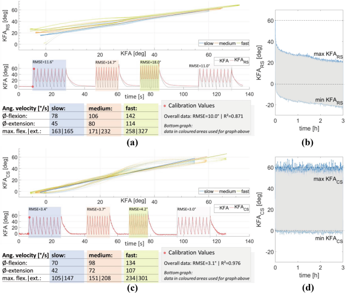
a+c Results for the RS and CS-system on the knee flexion test rig for three different speed settings (slow, medium, fast). The setting ‘slow’ was repeated at the end to test for repeatability. RS/CS-values calibrated with the min. and max. values of the first flexion (red markers in the graph (a) and (c)). Mean and maximal angular velocities for the three speed settings are given below the graphs. The top graph shows the dependence on the flexion/extension velocity. The bottom graph shows a comparison of KFA and RS-values (a) and CS-values (c). The black line shows the true KFA measured by a hall-sensor goniometer: the red line shows the respective RS/CS-values. b Long time drift of the sensor signal of the RS in a constant flexion–extension of the KFA between 0° and 60° for 3 h. d Long time behaviour of CS (colour figure online)
-
(2)
Long term test: The prototypes were calibrated at 0° and 60°. Then a three-hour measurement was recorded with a continuous flexion between 0° and 60° in the ‘slow’ setting (about 6,100 flexions and extensions) and a measurement frequency of 100 Hz, both for RS and CS measurements. No filter was used.

2.3 Human participant study
This study received ethical clearance by the Ethics Commission of the Technical University of Munich (Ref.nr.: 38/20 S). All participants were informed about the goals and risks of this study and gave their written consent. Twenty participants (7 male, 13 females, mean age 23.3 ± 6.23 years, no self-reported injuries, self-reported high fitness level) performed flexion–extension movements wearing both prototypes. For the RS only the knee part of the pants was used (see Fig. 4d). The participants were asked to stand in a ski binding on a platform with an inclination of 15°, wearing the same ski boot model in their shoe size (Mindbender, K2, Seattle, Washington, USA; Flexion Index 130 for male and 110 for female). This setup was chosen to simulate ski-like flexion behaviour and to represent the fixation of the ankle by the ski boot.

Exemplary results for a male participant: Measurements a with the RS and b with the CS vs. the knee angle recorded by the camera-based MTS, Bland Altmann diagram c of the results of the RS, and d of the CS after knee angle calculation using a two-point calibration, e participant wearing the RS-System (1), f participant wearing the CS-system (2). Participants wore ski boots in a ski binding (3), which was fixed on a platform (4) with a 15° inclination. The three coloured LED-markers (green, red, blue) are used by the MTS to determine the KFA (colour figure online)
The maximal and minimal values of the first flexion were used to calibrate the respective system. Camera-based automatic 2D-Motion-Tracking (Contemplas, Kempten, Germany) was used as the reference system (MTS). For the tracking, markers were attached to the condylus lateralis femoris (red marker) and 15 cm in both directions on the axis between the first marker and the trochanter major femoris (green marker) and the first marker and the malleolus lateralis (blue marker) (Figs. 4e, f). A manual trigger was used to mark the start and end of the measurement and turn on an LED attached to the ski boot. Measurement frequencies were 500 Hz for the CS-prototype, 1 kHz for the RS-prototype, 100 Hz for the MTS. MATLAB was used for the post-processing. MTS data was up-sampled by linear interpolation to 500 Hz and 1 kHz for comparison with CS and RS-data. For the synchronisation, the data was shortened using the trigger and LED signal, then cross-correlation was calculated to determine the time lag between MTS and the respective elongation sensor. The first flexion was used to calibrate the sensor. Bland–Altman-plots [30] were used to compare elongation sensor and MTS results over the whole range of the KFA. Before the start of the measurement, the participants were asked to perform two squats so the pants and sensors could align. At the start of the measurement, the participants were asked to flex the knee as deep as they voluntarily could (~ 120°), followed by ten squats to about 90° KFA. A metronome of 50 beats per minute gave an orientation for the speed of flexion for these ten squats. Each beat marked a turning point from flexion to extension and vice versa. Participants were asked to hold their arms horizontally, so as not to interfere with the MTS. Exemplary video recordings of the human participant test are provided in the supplementary materials of this study.
3 Results
3.1 Results artificial leg tests with the prototypes
3.1.1 Influence of velocity
Figure 3a, c shows the calibrated KFA of RS (KFARS) and CS (KFACS) against the ‘true’ KFA. In the upper graph, a linear trend for each velocity setting is plotted to allow better comparison. The respective lower graph shows the timeline of the same test. The RS-system was sensitive to the velocity of the flexion–extension movement (Fig. 3a). The sensor signal drifted to higher values for higher velocities, reflecting the mechanical properties of RS reported by others [24]. The influence was greater for smaller flexion angles (< 30°). A 5° increase of the trendline values from slow to medium speed and again from medium to fast speed at 0° KFA was observable. For 50° KFA there was only a 1° increase for the trendline values for both speed steps. A repetition of the slow speed setting resulted in the same value range as before (similar root mean squared error (RMSE) of 11.6° vs 11.0°; see Fig. 3a). Hysteresis was higher for KFA between 0 and 30° than for larger KFA. Hysteresis increased with velocity for the RS. R2 of KFA and KFARS over the whole measurement was 0.871, RMSE was 10.0°.
The velocity dependence for the CS was smaller than for the RS (Fig. 3c), with a 1° increase of the trendline values for both velocity steps at 0° KFA and a 1.2° decrease for both velocity steps at 50° KFA. At 30° KFA no influence was observable. This point marked the turning point from an increasing effect of the velocity to a decreasing effect. At the same KFA, the hysteresis was the smallest. The effect of the velocity on hysteresis was small for the CS. R2 of KFA and KFACS over the whole measurement was 0.976, RMSE was 3.0°.
3.1.2 Long-term test
The behaviour of maximum and minimum flexion values of the long-term tests are shown in Fig. 3b for RS and (d) for CS. A relaxation of the RS-signal over 3 h of 40° for the maximum values and 20° for the minimum values was observed (Fig. 3b). No large displacement of the prototype relative to the leg surrogate was observed during the measurement, which could have explained the relaxation. The CS showed close to no relaxation during the 3 h-test (Fig. 3d) but showed considerable variation for the maximum and minimum values.
3.2 Results human participant study
Figures 4a–d show the results for a male participant doing the eleven flexion–extension movements wearing the RS-prototype and CS-prototype, respectively. As observed in Fig. 4a, c, the RS is constantly overestimating the flexion angle for the ten movements following the first flexion by 12 ± 7.5°. The CS (Fig. 4b, d) shows superior behaviour, with a mean deviation of − 3.3 ± 5.6°. However, in Fig. 4 (d), the CS-values of the flexion appear to overestimate, and the CS-values of the extension underestimate the true KFA.
Across all tests by sensory type, the mean deviation between sensor and MTS system was 10.6 ± 7.5° for RS and 3.4 ± 5.1°for CS. The mean R2 across all participants is 0.92 for the RS-prototype, and 0.97 for the CS-prototype. Mean angular velocities were 53 ± 6.5°/s and − 55 ± 7.4°/s for flexion and extension (Table 1). Maximal angular velocities were 197 ± 27°/s to − 199 ± 49°/s for flexion and extension (Table 1).
4 Discussion
4.1 Artificial leg tests
The RS was sensitive to the speed with which the elongation was applied, as well as a long-term drift, which reflects the typical mechanics of elastomeric fabrics [22, 29, 31]. In future skiing applications, the calibration would take place before skiing in a quasi-static way. Thus, the velocity dependence would not allow reliable determination of the KFA in dynamic skiing afterwards. Perhaps modelling the dependence could improve results, but a critical concern is the long-term relaxation of the signal, which leads to more substantial errors as the time from the last calibration increases. If the dynamic and long-term characteristics of the RS-fibre could be modelled, the prototype could be promising: RS-fibre and its textile integration show positive attributes for wearability, washability, and the simple measuring principle requiring only standard and robust electronics.
The CS was superior, with less drift and an overall RMSE of 3.0°, compared to the RS, with an overall RMSE of 10°, and thus is recommended for use in skiing underpants. The CS prototype shows a limitation to accurately record maximum and minimum values. Besides sensor inherent characteristics, attributes of the garment and the type of attachment to the garment may be reasons for this behaviour. Future research will need to address this aspect. Disadvantages of CS compared to RS include more complex electronics necessary for capacitive measurements, a limited sample rate, and a more complex integration in the textile.
The mean velocities of the test rig for CS were 5–10% slower than for RS. This may result from a different stiffness of the pants and the limitation of using an analogue manometer for setting the pressure, which may impact repeatability. Also, the test rig reached higher flexion angles for higher velocities (about 5 to 7° increase for each velocity step) due to imperfect control of the pneumatic system. This could influence the results but was neglected as both sensor systems were affected by it.
4.2 Calibration process
The calibration process is critical to the accuracy of the knee angle measurements for both systems. A two-point calibration was used in this study, which is easy to perform but has limitations. As the knee is not a hinge joint, the postulation of the linear relationship between the elongation of the sensor and the knee flexion angle is incorrect, and non-linearities might increase measurement errors. For a skier, it may be challenging to take the exact positions for calibration. The calibration should be repeated throughout the ski day to correct errors due to the potential movement of the garment and sensors relative to the body, as well as potential sensor drift. A possible calibration procedure for a two-point-calibration could be that the skier is asked to stand straight and sit on a bench or chair lift with 90° KFA. If the calibration is not performed with great precision, this procedure might lead to large errors in the determination of the calibration coefficients. For a future commercial product, different and more robust calibration procedures should be considered or developed. For example, a dynamic calibration in which the skier performs (multiple) flexions in the knee’s full range of motion. This dynamic calibration, possibly combined with a learning algorithm, would therefore include viscoelastic behaviour. The resulting sensor values would not be absolute values for the knee flexion but a normalised value of the individual’s flexion range.
4.3 Human participant study
Results of the human subject tests are comparable to Petushek et al.’s [16] results, which used a goniometer with an RMSE of 7.03° ± 2.69°. The accuracy of both systems was lower for a straight leg compared to a leg in medium or deep flexion. One reason might be that the pants textile is tighter on the skin in a flexed state due to muscle volume change. The design of the textile’s stretching behaviour has a high impact on the measurements. Anisotropic stretch-design could improve the quality of measurements with a stiffer design in the circular direction. Current research is working on more suitable materials [32] and textile integration [29, 33] for more accurate and robust sensors for human motion tracking. Harms et al. [34] provide an example of more complex sensor modelling to improve results by modelling textile wrinkles. Nevertheless, Harms et al. do not aim to measure absolute angles but only recognise postures.
4.4 General discussion
The current system tested only addresses flexion and extension of the leg in a limited knee flexion range of 0 to 60° knee angle. Maximum ACL-loading in skiing occurs in hyperextension and hyperflexion of the leg combined with tibial torque (and rotation) [35]. As this study was an initial study to test the feasibility of the two different sensor principles, the exposure of the participants to the risk of injury by testing hyperflexion movements was kept to a minimum by asking them for only one deep flexion movement. Also, our flexion test rig is limited to the tested flexion range. Future work should consider more critical situations with respect to knee angle and angular velocities that result in knee injuries. For flexion movements, the experimental maximal angular velocities of the test rig and the human subject study were within the range of velocities measured on the slope by Petrone et al. [36], who used biplanar electrogoniometers. For extension movements, the maximal angular velocities are slower than reported by Petrone et al..
More than one sensor is needed to cope with the complex characteristics of human motion (e.g., measuring rotation, flexion, and ad-/abduction of the tibia vs. femur), which requires sensor fusion and effective algorithms [37]. In this study, the influence of knee movements in other dimensions than the sagittal plane was not investigated. Rotations of the tibia and abduction and adduction of the knee will likely influence the sensor output. Quantification and control of such will be necessary for successful integration in a wearable system. Pilot tests to measure tibial rotation with our two proposed sensors were unsatisfying. Soft tissue artefacts and relative movement between skin and textile heavily impacted the results. A small stretchable sensor based on carbon black filled silicon for measuring rotations was presented by Li et al. [38]. The proposed method should be modified and tested for human motion tracking.
The challenges of measuring joint angles with textile-integrated sensors are still manifold [28, 33, 39]. Nevertheless, more and more technical textiles appear on the consumer market [39] that reach an applicable state and fulfil the customer’s needs. The most promising solution for joint angle determination could be the hybrid use of IMUs and a stretchable CS. IMUs are accurate and can record rotations and translations in all directions. A CS and a Kalman filter could control the drift of the IMU.
5 Conclusion
Flexible sensors integrated into compression underwear can provide valuable data of the knee angles for performance measurements in sports or safety systems, and thus may help to reduce knee injuries. We developed two prototypes of technical pants to measure knee flexion angles in skiing: one using a resistive sensing fibre and one based on capacitive sensing elements. We postulated that a proper calibration process allows a calculation of the knee flexion from the change of the sensors’ electrical properties. The CS-system performed better than the RS-system, with good accuracy and high correlation to the reference system.
References
Rossi MJ, Lubowitz JH, Guttmann D (2003) The skier’s knee. Arthroscopy 19:75–84. https://doi.org/10.1053/jars.2003.50027
Bianchi G, Brügger O (2016) Unfallgeschehen beim Ski- und Snowboardfahren in der Schweiz: Unfallausmass, Risikoabschätzung und Entwicklung. Bfu—Beratungsstelle für Unfallverhütung. bfu Grundlagen. Doi: https://doi.org/10.13100/bfu.2.286.01
Schulz D (2018) Unfälle und Verletzungen im alpinen Skisport: Zahlen und Trends der Saison 2017/2018, Düsseldorf: ASU - Auswertungsstelle für Skiunfälle - ARAG Sportversicherung 2018. https://www.stiftung.ski/fileadmin/user_upload/ASU_Analyse_2017_2018.pdf
Ekeland A, Rødven A, Heir S (2019) Injuries among children and adults in alpine skiing and snowboarding. J Sci Med Sport 22(Suppl 1):S3–S6. https://doi.org/10.1016/j.jsams.2018.07.011
Finch CF, Kelsall HL (1998) The effectiveness of ski bindings and their professional adjustment for preventing alpine skiing injuries. Sports Med 25:407–416. https://doi.org/10.2165/00007256-199825060-00004
Shealy JE, Ettlinger CF, Johnson RJ (2003) What do we know about ski injury research that relates binding function to knee and lower leg injuries? In: Johnson RJ, Lamont MK, Shealy JE et al (eds) Skiing trauma and safety: fourteenth volume. ASTM International, Philadelphia, pp 36–52
Freudiger S, Friederich NF (2001) Critical load cases for knee ligaments at skiing - An engineering approach. ASTM Special Technical Publication, (1397), pp 160–174
Wascher DC, Markolf KL, Shapiro MS et al (1993) Direct in Vitro measurement of forces in the cruciate ligaments: part i: the effect of multiplane loading in the intact knee. J Bone Joint Surg 75:377–386
Hermann A, Senner V (2020) Knee injury prevention in alpine skiing A technological paradigm shift towards a mechatronic ski binding. J Sci Med Sport. https://doi.org/10.1016/j.jsams.2020.06.009
Senner V, Lehner S, Nusser M et al. (2014) Skiausrüstung und Knieverletzungen beim alpinen Skifahren um Freizeitsport: Eine Expertise zum gegenwärtigen Stand der Technik und deren Entwicklungspotential, bfu Report 69, Bern
Senner V, Michel FI, Lehner S et al (2013) Technical possibilities for optimising the ski-binding-boot functional unit to reduce knee injuries in recreational alpine skiing. Sports Eng 16:211–228. https://doi.org/10.1007/s12283-013-0138-7
Sandau M, Koblauch H, Moeslund TB et al (2014) Markerless motion capture can provide reliable 3D gait kinematics in the sagittal and frontal plane. Med Eng Phys 36:1168–1175. https://doi.org/10.1016/j.medengphy.2014.07.007
Gatt IT, Allen T, Wheat J (2020) Accuracy and repeatability of wrist joint angles in boxing using an electromagnetic tracking system. Sports Eng. https://doi.org/10.1007/s12283-019-0313-6
Bronner S, Agraharasamakulam S, Ojofeitimi S (2010) Reliability and validity of electrogoniometry measurement of lower extremity movement. J Med Eng Technol 34:232–242. https://doi.org/10.3109/03091900903580512
Rowe PJ, Myles CM, Hillmann SJ et al (2001) Validation of flexible electrogoniometry as a measure of joint kinematics. Physiotherapy 87:479–488. https://doi.org/10.1016/S0031-9406(05)60695-5
Petushek E, Richter C, Donovan D et al (2012) Comparison of 2D video and electrogoniometry measurements of knee flexion angle during a countermovement jump and landing task. Sports Eng 15:159–166. https://doi.org/10.1007/s12283-012-0094-7
Yoshioka S, Fujita Z, Hay DC et al (2018) Pose tracking with rate gyroscopes in alpine skiing. Sports Eng 21:177–188. https://doi.org/10.1007/s12283-017-0261-y
Fasel B, Spörri J, Schütz P et al (2017a) An inertial sensor-based method for estimating the athlete’s relative joint center positions and center of mass kinematics in alpine ski racing. Front Physiol 8:850. https://doi.org/10.3389/fphys.2017.00850
Fasel B, Spörri J, Schütz P et al (2017b) Validation of functional calibration and strap-down joint drift correction for computing 3D joint angles of knee, hip, and trunk in alpine skiing. PLoS ONE 12:e0181446. https://doi.org/10.1371/journal.pone.0181446
Supej M (2010) 3D measurements of alpine skiing with an inertial sensor motion capture suit and GNSS RTK system. J Sports Sci 28:759–769. https://doi.org/10.1080/02640411003716934
Pettys-Baker R, Compton C, Utset-Ward S, Tompkins M, Holschuh B, Dunne LE (2017) Design and development of valgus-sensing leggings. Paper presented at the Frontiers in Biomedical Devices, BIOMED - 2017 Design of Medical Devices Conference, DMD 2017. https://doi.org/10.1115/DMD2017-3526
Mattmann C, Clemens F, Tröster G (2008) Sensor for measuring strain in textile. Sensors 8:3719–3732. https://doi.org/10.3390/s8063719
Yamada T, Hayamizu Y, Yamamoto Y et al (2011) A stretchable carbon nanotube strain sensor for human-motion detection. Nat Nanotechnol 6:296–301. https://doi.org/10.1038/nnano.2011.36
Bergmann JHM, Anastasova-Ivanova S, Spulber I et al (2013) An attachable clothing sensor system for measuring knee joint angles. IEEE Sens J 13:4090–4097. https://doi.org/10.1109/JSEN.2013.2277697
Munro BJ, Campbell TE, Wallace GG et al (2008) The intelligent knee sleeve: a wearable biofeedback device. Sens Actuators B Chem 131:541–547. https://doi.org/10.1016/j.snb.2007.12.041
Shyr T-W, Shie J-W, Jiang C-H et al (2014) A textile-based wearable sensing device designed for monitoring the flexion angle of elbow and knee movements. Sensors (Basel) 14:4050–4059. https://doi.org/10.3390/s140304050
Amjadi M, Kyung K-U, Park I et al (2016) Stretchable, skin-mountable, and wearable strain sensors and their potential applications: a review. Adv Funct Mater 26:1678–1698. https://doi.org/10.1002/adfm.201504755
Qiu A, Li P, Yang Z et al (2019) A path beyond metal and silicon:polymer/nanomaterial composites for stretchable strain sensors. Adv Funct Mater 29:1806306. https://doi.org/10.1002/adfm.201806306
Gioberto G, Compton C, Dunne L (2016) Machine-stitched e-textile stretch sensors. Sens Transducers 202:25–37
Bland JM, Altman DG (1986) Statistical methods for assessing agreement between two methods of clinical measurement. Lancet 1:307–310
Tognetti A, Bartalesi R, Lorussi F et al (2007) Body segment position reconstruction and posture classification by smart textiles. Trans Inst Meas Control 29:215–253. https://doi.org/10.1177/0142331207069487
Li Y, He T, Shi L et al (2020) Strain sensor with both a wide sensing range and high sensitivity based on braided graphene belts. ACS Appl Mater Interfaces 12:17691–17698. https://doi.org/10.1021/acsami.9b21921
Wang L, Fu X, He J et al (2020) Application Challenges in Fiber and Textile Electronics. Adv Mater Weinheim 32:e1901971. https://doi.org/10.1002/adma.201901971
Harms H, Amft O, Tr Ster G (2010) Estimating posture-recognition performance in sensing garments using geometric wrinkle modeling. IEEE Trans Inf Technol Biomed 14:1436–1445. https://doi.org/10.1109/TITB.2010.2076822
Hame SL, Oakes DA, Markolf KL (2002) Injury to the anterior cruciate ligament during alpine skiing: a biomechanical analysis of tibial torque and knee flexion angle. Am J Sports Med 30:537–540. https://doi.org/10.1177/03635465020300041301
Petrone N, Marcolin G, Panizzolo FA (2013) The effect of boot stiffness on field and laboratory flexural behavior of alpine ski boots. Sports Eng 16:265–280. https://doi.org/10.1007/s12283-013-0133-z
Mendes JJA, Vieira MEM, Pires MB et al (2016) Sensor fusion and smart sensor in sports and biomedical applications. Sensors. https://doi.org/10.3390/s16101569
Li M, Assadian M, Ramezani M et al (2019) Printed soft angular/torque sensors using carbon black-silicone composite. Sens Rev 39:598–603. https://doi.org/10.1108/SR-11-2018-0290
Muhammad Sayem AS, Hon Teay S, Shahariar H et al (2020) Review on smart electro-clothing systems (SeCSs). Sensors. https://doi.org/10.3390/s20030587
Acknowledgments
We thank the University of Reutlingen and Peter Müller GmbH for manufacturing the textile prototypes of the RS-System. The research is funded by the Bayerische Forschungsstiftung, Grant #AZ-1375-19. Yakira Mirabito was supported by the NSF IRES-1460031 NanoRING program and the International Graduate School for Science and Engineering at the Technical University of Munich.
Funding
Open Access funding enabled and organized by Projekt DEAL.
Author information
Authors and Affiliations
Corresponding author
Ethics declarations
Conflict of interest
The authors declare that they have no conflict of interest.
Additional information
Publisher's Note
Springer Nature remains neutral with regard to jurisdictional claims in published maps and institutional affiliations.
This article is a part of Topical Collection in Sports Engineering on Winter Sports, edited by Dr. Aimee Mears, Dr. David Pearsall, Dr. Irving Scher and Dr. Carolyn Steele.
Electronic supplementary material
Below is the link to the electronic supplementary material.
Supplementary file1 (MP4 21396 KB)
Supplementary file2 (MP4 17808 KB)
Supplementary file3 (MP4 19747 KB)
Supplementary file4 (MP4 36803 KB)
Rights and permissions
Open Access This article is licensed under a Creative Commons Attribution 4.0 International License, which permits use, sharing, adaptation, distribution and reproduction in any medium or format, as long as you give appropriate credit to the original author(s) and the source, provide a link to the Creative Commons licence, and indicate if changes were made. The images or other third party material in this article are included in the article's Creative Commons licence, unless indicated otherwise in a credit line to the material. If material is not included in the article's Creative Commons licence and your intended use is not permitted by statutory regulation or exceeds the permitted use, you will need to obtain permission directly from the copyright holder. To view a copy of this licence, visit http://creativecommons.org/licenses/by/4.0/.
About this article

Cite this article
Hermann, A., Ostarhild, J., Mirabito, Y. et al. Stretchable piezoresistive vs. capacitive silicon sensors integrated into ski base layer pants for measuring the knee flexion angle. Sports Eng 23, 22 (2020). https://doi.org/10.1007/s12283-020-00336-9
Accepted:
Published:
DOI: https://doi.org/10.1007/s12283-020-00336-9