
Abstract
As discussed in Chap. 2, information in classical computers is represented by bits. However, if the bits did not change, then the computer would remain the same forever and would not be very useful! Therefore, it is necessary to change the values of bits depending on what you want the computer to do. For example, if you want a computer to multiply the number 2 and the number 3 together to produce the number 6, then you need to put each of the numbers 2 and 3 into an 8-bit binary representation, and then have a computational operation to multiply the two 8-bit values together to produce 6. The operation of changing bits in a classical computer is performed by classical logic gates.
Electronic Supplementary Material The online version of this chapter (https://doi.org/10.1007/978-3-030-61601-4_6) contains supplementary material, which is available to authorized users.
You have full access to this open access chapter, Download chapter PDF
As discussed in Chap. 2, information in classical computers is represented by bits. However, if the bits did not change, then the computer would remain the same forever and would not be very useful! Therefore, it is necessary to change the values of bits depending on what you want the computer to do. For example, if you want a computer to multiply the number 2 and the number 3 together to produce the number 6, then you need to put each of the numbers 2 and 3 into an 8-bit binary representation, and then have a computational operation to multiply the two 8-bit values together to produce 6. The operation of changing bits in a classical computer is performed by classical logic gates.
6.1
 Single Qubit Gates
 Single Qubit Gates
Classical computers manipulate bits using classical logic gates such as OR, AND, NOT and NAND. This linkFootnote 1 provides a basic review of classical logic gates. Similarly, quantum computers manipulate qubits using quantum gates . The gates are applied to qubits and the states of the qubits change depending on which gate is applied. In the Bloch sphere representation, the gate provides instructions for rotating the qubit’s arrow around the sphere. A quantum algorithm has to be implemented on a quantum computer using quantum gates. After running a quantum algorithm, the result is retrieved by measuring the qubit’s state. The hardware implementation of quantum gates depends on how the qubit and quantum computer has been implemented technologically.Footnote 2 As an example, one could have a qubit based on spin. Then gates could be implemented using an external magnetic field to change the spin and hence the qubit state. This chapter will focus on gates from the computing perspective rather than the engineering perspective. You will learn about several important gates that act on a single qubit, interpret histograms produced by a quantum computer simulator, and use matrices to describe the operation of these gates.
6.2
 X (Also Called NOT) Gate
 X (Also Called NOT) Gate
In classical computers, the NOT gate takes one input and reverses its value. For example, it changes the 0 bit to a 1 bit or changes a 1 bit to a 0 bit. This is like a light-switch flipping a light from ON to OFF, or from OFF to ON. A quantum X gate is similar in that a qubit in a definite state |0〉 will become |1〉 and vice versa. When the qubit is in a superposition of all basis states, then the superposition also flips:

To see how this works, you can try out the IBM Q simulator.Footnote 3 Traditionally, all qubits on the IBM Q machine (or any other quantum simulator) start with the incoming qubits in the |0〉 state. To run this simple gate, drag the X gate onto any qubit. To find the results, add the measurement operation at the end, as shown in Fig. 6.1. Figure 6.1 is known as a quantum circuit, the quantum analog to classical circuits. A circuit describes how a qubit changes through a computation depending on which gates act on it. The circuit is read from left to right. As an example, in Fig. 6.1 the single qubit on the left is initialized to |0〉. An X gate is then applied to that specific qubit, and the last symbol on the qubit line denotes that the qubit is measured. The double line underneath is used to illustrate the measurement.

Applying the X gate on the IBM Q simulator and measuring the output
After running the quantum circuit and opening the results, you should see a histogram showing the measurements of the qubit’s final state for 1,024 independent trial runs. As the qubit always starts as the |0〉 state, applying the X gate produces the |1〉 state and so the measurement outcome is |1〉 100% of the time as shown in Fig. 6.2.

Histogram showing that the qubit is measured in the |1〉 state with a probability of 1. Reprint Courtesy of International Business Machines Corporation. ⒸInternational Business Machines Corporation
Mathematically, the quantum NOT gate is represented as a matrix X which acts on qubit states using matrix multiplication. The matrix representation is
It is worth noting that any computer will have hardware errors. In a classical computer, this could be an electrical short of the motherboard, or degradation of the hard drive which corrupts the stored classical bits. A real quantum computer will also have hardware errors. The quantum state of a qubit can change accidentally because of these hardware errors. Such errors may arise from the lack of full control of the interference between electromagnetic fields, variations in temperature, or energy dissipation. The accidental and incorrect change of a qubit state gives rise to the wrong answer which is called “noise”.Footnote 4 As quantum computers only measure the state of a qubit, they cannot easily tell if the measurement is correct or incorrect. When we humans interpret these results, noise can cause confusion as to which answer is actually correct. Minimizing noise error is the greatest obstacle to building quantum computers.Footnote 5 For example, noise will cause the histogram in Fig. 6.2 to not have the perfect 100% outcome. Instead, noise will cause the qubit to be in the |0〉 state incorrectly some of the time, and the measurement histogram will incorrectly be x% in the |0〉 state and (100 − x)% in the |1〉 state. If the noise is large, then x = 50% and the measurement will be completely random. It should be understood that noise is an effect that occurs in both classical and quantum computers but because quantum computing technology is in its infancy, the noise is not as well under control.
6.3
 Hadamard Gate
 Hadamard Gate
The Hadamard gate is very important in quantum computing. If the qubit starts in a definite |0〉 or |1〉 state, the Hadamard gate puts each into a superposition of |0〉 and |1〉 states. In Fig. 6.3, we apply a Hadamard gate to the |0〉 state qubit on the IBM Q simulator and measure the output.

Applying a Hadamard gate and measuring on the IBM Q machine
The result of running the circuit 100 times is a histogram shown in Fig. 6.4. Note that each run is independent: before each measurement, the qubit has to be reset to the |0〉 state and passed through the gate, and then the measurement happens. We repeat this process 1024 times. Each bin in the histogram shows the frequency/probability of measuring |0〉 or |1〉. You can clearly see that applying the Hadamard gate to a single qubit creates a superposition state of both |0〉 and |1〉. The probabilities are not exactly 50∕50 because of statistical error. The more data you collect, the closer the result converges to 50∕50. This is similar to flipping a coin and counting the number of heads or tails; the greater the number of flips, the more likely you are to observe 50∕50 probability of seeing heads/tails.

Measurement histogram after running the Hadamard gate circuit in Fig. 6.3 1024 times. Reprint courtesy of International Business Machines Corporation, ⒸInternational Business Machines Corporation
Recall that measurement collapses the superposition. Only one classical state can be observed, and all of the other quantum information is lost. Measurement collapse is the reason why a qubit’s state cannot be duplicated, known as the no-cloning theorem of quantum computing. Once a superposition state is measured, it fundamentally changes into one of the basis states, and hence cannot be duplicated. Still, it is not known how or whether measurement collapse happens.Footnote 6
Question 1
Create a qubit in the |1〉 state and pass it through a Hadamard gate. From the measurement histogram, can you tell whether the qubit started in a |0〉 or |1〉 initial state?
The measurement histogram should look identical whether |0〉 or |1〉 was the initial state. Then how can we tell what the initial state was after a Hadamard operation? In the beam splitter, we determined where the photon came from by adding a second beam splitter to create interference. The way to measure and distinguish between them is to add a second Hadamard gate.
Question 2
Build a circuit that applies two Hadamard gates to a qubit in the |0〉 initial state as shown in Fig. 6.5. What is the output? Repeat this experiment for the |1〉 initial state.

Applying two Hadamard gates to the |0〉 state or |1〉 state
6.4
 Mathematics of the Hadamard Gate
 Mathematics of the Hadamard Gate
The Hadamard gate has the following matrix representation:
Using matrix multiplication we can show that application of the Hadamard gate to an |0〉 initial state puts the qubit into the \((1/\sqrt {2})(|0\rangle + |1\rangle )\) state, also called the |+〉 state:

If the initial state is |1〉, the Hadamard gate will create the superposition \((1/\sqrt {2})(|0\rangle - |1\rangle )\) state, called the |−〉:

In the Stern–Gerlach experiment, you learned that the |0〉 and |1〉 states make up the z-basis and are associated with spin up and spin down. The |+〉 and |−〉 states comprise the x-basis and are associated with spin right and spin left. While the Stern–Gerlach could be rotated to measure at any angle, a quantum computer is physically built to only measure in the z-basis. Therefore, the spin right \(1/\sqrt {2}(|0\rangle + |1\rangle )\) and spin left \(1/\sqrt {2}(|0\rangle - |1\rangle )\) look the same when measured by a quantum computer. However, the two states have hidden information that can be recovered by using a second Hadamard gate to change back into the z-basis.
6.4.1 Examples
-
1.
A spin right \(1/\sqrt {2}(|0\rangle + |1\rangle )\) is sent through a Hadamard gate, creating a superposition of |+〉 and |−〉 given by \(1/\sqrt {2}(|+\rangle + |-\rangle )\). By performing a basis change, show that this is equivalent to producing a |0〉 state.
$$\displaystyle \begin{aligned} \frac{1}{\sqrt{2}}\Big(|+\rangle + |-\rangle\Big) & = \frac{1}{\sqrt{2}}\Big(\frac{1}{\sqrt{2}}|0\rangle + \frac{1}{\sqrt{2}}|1\rangle\Big) + \frac{1}{\sqrt{2}}\Big(\frac{1}{\sqrt{2}}|0\rangle - \frac{1}{\sqrt{2}}|1\rangle\Big), \end{aligned} $$(6.6)$$\displaystyle \begin{aligned} & = \frac{1}{{2}}|0\rangle + \frac{1}{{2}}|1\rangle + \frac{1}{{2}}|0\rangle - \frac{1}{{2}}|1\rangle, \end{aligned} $$(6.7)$$\displaystyle \begin{aligned} & = |0\rangle. \end{aligned} $$(6.8) -
2.
Use matrix multiplication to show how applying the Hadamard gate twice to a |0〉 state qubit recovers its original state.
$$\displaystyle \begin{aligned} H|0\rangle &=\frac{1}{\sqrt{2}} \begin{pmatrix} 1 & 1 \\ 1 & -1 \end{pmatrix} \begin{pmatrix} 1 \\ 0 \end{pmatrix} = \frac{1}{\sqrt{2}} \begin{pmatrix} 1 \\ 1 \end{pmatrix}, \end{aligned} $$(6.9)$$\displaystyle \begin{aligned} HH|0\rangle &=\frac{1}{{2}} \begin{pmatrix} 1 & 1 \\ 1 & -1 \end{pmatrix} \begin{pmatrix} 1 \\ 1 \end{pmatrix} = \begin{pmatrix} 1 \\ 0 \end{pmatrix}. {} \end{aligned} $$(6.10)In fact, all quantum gates are reversible as a consequence of the unitary matrix condition. Recall that the gates must be unitary so that the probabilities always add up to 1. Multiplying any unitary matrix by its conjugate transpose will return the identity matrix, i.e., reverses the gate to get the original state by UU † = U † U = 1. The Hadamard matrix is self-unitary, i.e., it is its own conjugate transpose, U = U †.
6.5
 Z Gate
 Z Gate
The Z-gate matrix representation is
The Z gate leaves a |0〉 state unchanged but flips the sign of the |1〉 state to −|1〉 by

This is equivalent to changing the qubit from a |+〉 state to a |−〉 state. The effects of the X, H, and Z gates are summarized in Fig. 6.6.

The X, H, and Z gates change the qubit’s state in the z- and x-basis and are related according to this diagram
6.6 Big Ideas
-
1.
Every interaction with a classical computer is caused by code instructing classical logic gates to operate on classical bits. Similarly, a calculation on a quantum computer is caused by coding quantum logic gates to act on qubits.
-
2.
Common single-qubit gates include the X, Z, and H (Hadamard) gates.
-
3.
Each quantum gate can be mathematically represented as a unitary matrix which acts on qubits.
6.7 Activities
 Exploring gates on the IBM Quantum Computer 10.4.
6.8 Check Your Understanding
-
1.
 Use matrix multiplication to show how applying an X gate flips:
-
(a)
A qubit in the |0〉 state.
-
(b)
A qubit in the general |ψ〉 = α|0〉 + β|1〉 state.
-
(a)
-
2.
 Explain the relationship between a beam splitter and a Hadamard gate.
 -
3.
 A |0〉 qubit is passed through a Hadamard gate. We measure the qubit state as |1〉. Which of the following choices best describes the result if we perform a measurement on the qubit a second time without reinitializing?
-
(A)
|0〉
-
(B)
|1〉
-
(C)
50% chance of |0〉 or |1〉
-
(A)
-
4.
 Assume a qubit represents a light bulb that can be measured as either ON or OFF.
-
(a)
The light bulb is originally ON. What gate would you use to turn it OFF?
-
(b)
The light bulb is originally ON and passes through a Hadamard gate. What do you measure as the output?
-
(c)
The light bulb is originally ON and passed through two Hadamard gates in series. What do you measure as the output?
-
(a)
-
5.
 Explain how the Hadamard gate is implemented in the Stern–Gerlach experiment.
 -
6.
 Explain the output of the Mach–Zehnder interferometer using what you learned about Hadamard gates.
 -
7.
 Use matrix multiplication to demonstrate
 -
(a)
The Hadamard gate applied to a |1〉 state qubit turns it into a |−〉.
-
(b)
A second Hadamard gate turns it back into the |1〉 state.
-
(c)
The output after applying the Hadamard gate twice to a general state |ψ〉 = α|0〉 + β|1〉.
-
(a)
-
8.
 Which of the quantum circuits in the Fig. 6.7 would NOT produce the histogram shown in Fig. 6.4?
Fig. 6.7 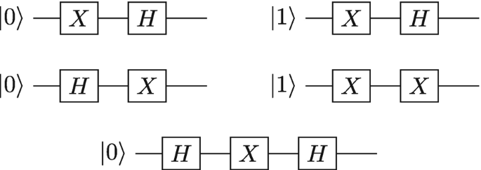
Five quantum circuits for Problem 8
-
9.
 Use matrix multiplication to show how applying the Z gate to |+〉 changes it to |−〉.
 -
10.
 Using only Hadamard and Z gates, design a quantum circuit that outputs the same result as an X gate.
 -
11.
 Using the IBM Q simulator, apply the Z gate to a qubit in the following initial states and interpret the measurement histogram.
 -
(a)
|0〉
-
(b)
|1〉 (Hint: You need to first flip the |0〉 state using the X gate.)
-
(c)
|+〉 (Hint: You need to first create the |+〉 state using the H gate.)
-
(d)
|−〉 (Hint: You need to first create the |−〉 state using the X and H gates.)
-
(a)
-
12.
 What is the expected measurement histogram produced by the circuit in Fig. 6.8?
Fig. 6.8 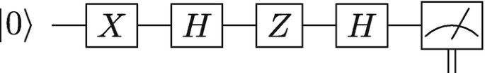
Circuit diagram for Problem 12
-
13.
 Show that the Hadamard gate is unitary and therefore reversible.
 Use matrix multiplication to show how applying an X gate flips:
 Explain the relationship between a beam splitter and a Hadamard gate.
 A |0〉 qubit is passed through a Hadamard gate. We measure the qubit state as |1〉. Which of the following choices best describes the result if we perform a measurement on the qubit a second time without reinitializing?
 Assume a qubit represents a light bulb that can be measured as either ON or OFF.
 Explain how the Hadamard gate is implemented in the Stern–Gerlach experiment.
 Explain the output of the Mach–Zehnder interferometer using what you learned about Hadamard gates.
 Use matrix multiplication to demonstrate
  Which of the quantum circuits in the Fig.
 Use matrix multiplication to show how applying the Z gate to |+〉 changes it to |−〉.
 Using only Hadamard and Z gates, design a quantum circuit that outputs the same result as an X gate.
 Using the IBM Q simulator, apply the Z gate to a qubit in the following initial states and interpret the measurement histogram.
  What is the expected measurement histogram produced by the circuit in Fig.
 Show that the Hadamard gate is unitary and therefore reversible.
Notes
- 1.
- 2.
E.g., topological qubits and superconducting qubits have very different hardware implementations due to their very different nature.
- 3.
https://quantum-computing.ibm.com. It can also be run on IBM’s real quantum computer, but you may have to wait in a queue for the results.
- 4.
Background noise is an event that causes unwanted or incorrect affects on a signal.
- 5.
Noise can also occur in classical computers. Here, it can be because a wire in the computer which holds the 0- or 1-bit breaks and gives the wrong bit value. However, since classical computation has no probability associated with it, a single classical computation can be rerun twice and should give the exact same result. In practice, your computer reruns the same code many times to spot if there has been any errors and chooses the result which occurs most frequently. In this way you do not notice the hardware noise as easily.
- 6.
Author information
Authors and Affiliations
Rights and permissions
Open Access This chapter is licensed under the terms of the Creative Commons Attribution 4.0 International License (http://creativecommons.org/licenses/by/4.0/), which permits use, sharing, adaptation, distribution and reproduction in any medium or format, as long as you give appropriate credit to the original author(s) and the source, provide a link to the Creative Commons license and indicate if changes were made.
The images or other third party material in this chapter are included in the chapter's Creative Commons license, unless indicated otherwise in a credit line to the material. If material is not included in the chapter's Creative Commons license and your intended use is not permitted by statutory regulation or exceeds the permitted use, you will need to obtain permission directly from the copyright holder.
Copyright information
© 2021 The Author(s)
About this chapter

Cite this chapter
Hughes, C., Isaacson, J., Perry, A., Sun, R.F., Turner, J. (2021). Quantum Gates. In: Quantum Computing for the Quantum Curious. Springer, Cham. https://doi.org/10.1007/978-3-030-61601-4_6
Download citation
DOI: https://doi.org/10.1007/978-3-030-61601-4_6
Published:
Publisher Name: Springer, Cham
Print ISBN: 978-3-030-61600-7
Online ISBN: 978-3-030-61601-4
eBook Packages: Physics and AstronomyPhysics and Astronomy (R0)