
Abstract
Many applications show an inherent error resilience due to their probabilistic behavior. This inherent error resilience can be exploited to reduce the design margin for advanced technology nodes resulting in more energy and area efficient implementation. We present in this chapter a cross-layer approach for efficient reliability management in wireless baseband processing with special emphasis on memories since memories are most susceptible to dependability problems. A multiple-antenna (MIMO) system will be used as design example. Further on we focus on DRAMs (Dynamic Random Access Memories). All today’s computing systems rely on dependable DRAMs. In the future DRAM memories will become more undependable due to further scaling. This has to be counterbalanced with higher refresh rates, which leads to a higher DRAM power consumption. Recent research activities resulted in the concept of “approximate DRAM” to save power and improve performance by lowering the refresh rate or disabling refresh completely. Here, we present a holistic simulation environment for investigations on approximate DRAM and show the impact on error-resilient applications.
You have full access to this open access chapter, Download chapter PDF
1 Introduction
Technology scaling has reached a point at which process and environmental variabilities are no longer negligible, and can no longer be hidden from system designers, as the exact behavior of CMOS devices becomes increasingly less predictable. This will show in the form of static and dynamic variations, time-dependent device degradation and early life failures, sporadic timing errors, radiation-induced soft errors, and lower resilience to varying operating conditions [35]. Already today, conservative margining, guardbanding, and conservative voltage scaling, come at a large cost. Only turning away from conservative worst-case design methodologies for a 100% reliable physical hardware layer will make further downscaling of CMOS technologies a profitable endeavor [7, 32]. This calls for radically new cross-layer-design concepts [14,15,16] (Fig. 1).

Main abstraction layers of embedded systems as used in the SPP1500 Dependable Embedded Systems Priority Program of the German Research Foundation (DFG) and this chapter’s major (green, solid) and minor (yellow, dashed) cross-layer contributions
Until today, these problems have mostly been addressed at the lower design levels. At the higher levels, systems are typically designed under the premise of fault-free underlying hardware. Only in extremely critical applications, such as avionics, where the system cost is less important than its dependability, triple modular redundancy (TMR) and similar techniques are employed on a system level. Thus, to no big surprise, the large body of related work focuses on low-level techniques to present higher abstraction and design levels with a practically error-free platform built from potentially faulty elements.
To make a platform resilient against transient or permanent faults built-in redundancy or built-in self-recovery techniques have to be employed. They all come at the cost of chip area, power consumption, reduced system throughput, or other implementation related metrics. Lower implementation cost, especially with regard to energy consumption can be obtained when a degradation of hardware reliability to a certain degree is tolerated. In fact, energy consumption and dependability of integrated circuits can be seen as strongly interrelated problems: by decreasing the operating voltage, the energy efficiency increases but at the same time the dependability decreases. Thus, energy efficiency and dependability have to be carefully traded off against each other.
An error-resilient architecture that can be seen as practically error-free can be composed of protected components. Applications for these platforms can be implemented in a traditional way, still assuming fault-free operation of the underlying hardware. In addition to this horizontal integration, recent research also evaluates the additional potential of a vertical integration of error resilience on the application level with platforms having a reduced reliability. True cross-layer optimization approaches do not only exploit the fact that some important classes of algorithms are inherently error-tolerant, but also adapt applications and hardware architectures jointly to achieve the best possible trade-offs. This chapter focuses on cross-layer optimization for wireless communication systems with emphasis on errors on data path and SRAMs. Furthermore, we consider undependable DRAM subsystems, named approximate DRAM.
2 Wireless Baseband Processing
In this section, we present a wireless baseband processing system and a novel cross-layer methodology using resilience actuators (see Sect. 2.1.2) to improve the reliability of this system. Wireless communication systems have an inherent error resilience. They are designed to recover the originally transmitted data sequence in spite of errors that occur during transmission over a noisy channel. Figure 2 shows a simplified structure of such a system. To achieve a reliable transmission, today’s communication systems use advanced forward error correction (FEC) techniques, i.e. the sender adds redundancy to the actual information prior to transmission in the channel encoder. This encoder connects to the modulator via an interleaver (Π). The interleaver is required to break dependencies between neighboring bits while the modulator performs the mapping on symbols (e.g. QAM—quadrature amplitude modulation) that are transmitted over the physical channel. On the receiver side, the noisy signal is converted to the digital domain and fed into the demodulator, which recovers the originally transmitted symbols by exploiting the channel characteristics. After the deinterleaver ( Π−1) the channel decoder uses the redundancy to correct transmission errors.

Wireless communication systems suffer from different sources of errors (indicated by red arrows): channel errors, quantization errors, errors from suboptimal algorithms, and hardware errors. Here, we focus on the receiver side only
The primary goal is to correct errors from the noisy channel. But implementation efficiency of communication systems in hardware mandates e.g. quantization of data values and the use of suboptimal algorithms, i.e., algorithms that generate results which deviate from the theoretically correct values. Both can be seen as further sources of errors in addition to the noise on channel. In the same way, errors induced by hardware faults can be considered as yet another error source in a communication system. The question is if the hardware errors can be processed in a similar way than the channel and what are the costs.
2.1 Methodology: Error Mitigation Using Dynamic Resilience Actuators
Modeling of hardware errors is crucial for the design of dependable systems. Radiation, thermal effects, aging, or process or parameter variations cause distortions on a physical level which can be modeled by probabilistic bit flips according to the resilience articulation point (RAP) model [16] (see also the chapter “RAP Model—Enabling Cross-Layer Analysis and Optimization for System-on-Chip Resilience” in this book). Depending on its location, a bit flip can have very different effects. An error in the controller, for example, usually leads to a system malfunction, whereas individual errors in the memories or the data flow are often inherently corrected by a wireless receiver ([12, 31]). Efficiency in terms of area and energy will be achieved by recovering only from those errors which have a significant impact on the system output and by choosing the layer on which the treatment of these error results in the least overhead.
Dynamic approaches for error resilience also have to monitor the current hardware status. This monitoring can be done on different abstraction layers. Examples are error detection sequential (EDS) circuits on microarchitectural layer. EDS circuits are very popular [6]; however, they require pre- and post-silicon calibration. Monitors on higher abstraction layers are application-specific and normally more efficient. For example, [3] proposed to detect timing errors with a small additional hardware block which mimics the critical path under relaxed timing constraints. The result of the mimic hardware is compared to the normally operating unit. Deviations indicate timing errors. For a turbo and convolutional code decoder, the mimic hardware only required 0.7% of the decoder area. In this article we focus on resilience techniques which are employed after hardware errors have been detected, not on the detection methods themselves.
Many state-of-the art publications utilize low-level static resilience techniques to combat the effects of unreliable hardware, e.g., ECC protection of memories, Razor flip flops, or stochastic logic [36]. Static methods have the disadvantage of permanently decreasing the system performance in at least one of the terms of throughput, area, or power, even when no errors occur. In [31] for example, the static protection of a complete LDPC (Low-Density Parity Check) decoder for WiMax/WiFi resulted in an area overhead of 21%.
Dynamic techniques often use available hardware resources or have very low additional costs as we will show in Sect. 2.2.1. However, error detection circuits result in additional costs. When comparing static and dynamic methods, this additional cost has to be taken into account. In general, the choice of the protection method will also depend on the expected hardware error statistics as we will demonstrate in the next paragraph. Eventually, a combination of static and dynamic protection will likely result in the least overhead.
2.1.1 The Dynamic Behavior of Wireless Systems
Modern wireless communication standards, such as LTE (Long Term Evolution) or HSDPA (High Speed Downlink Packet Access) provide mechanisms to monitor and dynamically adapt to changes in the Quality-of-Service (QoS). The QoS in a wireless transmission system is typically defined as the bit or frame error rate with respect to a given signal-to-noise ratio. If the desired QoS cannot be achieved for the current transmission channel, communication parameters like code type, code rate, etc. are adjusted to improve the communications performance (see Fig. 3a). A good example for this dynamic behavior is the hybrid automatic repeat request (H-ARQ), which is used in LTE, HSDPA. These systems typically transmit blocks of data at a high data rate and with little error protection, i.e., with a very high code rate. If the decoder fails, the transmission of additional data is requested until the block is correctly decoded. Note that such a retransmission does not contain the same data as before. Instead, different information will be sent every time, which had been punctured on the transmitter side before. The additional information decreases the data rate but at the same time increases the probability that the block can be correctly decoded at the receiver. Figure 3b shows the throughput of a H-ARQ system over different SNR values. For high SNR values, decoding succeeds after the first transmission, i.e., the channel decoder can correct all errors, and a high throughput is obtained. With a decreasing SNR, more and more blocks require additional transmissions and the throughput is lowered. The system dynamically adapts the code rate and the throughput for each block.

The standard communication flow dynamically adjusts communication parameters to achieve the required QoS, e.g., the code rate in Hybrid-ARQ systems. (a) Dynamic QoS flow of a modern wireless communication system. (b) In Hybrid-ARQ systems the code rate is dynamically adjusted for each block to ensure error-free transmission
This example shows how wireless receivers adapt dynamically to changes in the transmission channel, i.e., varying SNR, and correct transmission errors. The question is how this idea can be applied to the case of hardware errors. It has been shown that low rates of hardware errors in a wireless receiver are not visible on the system level. This is due to the fact that for low SNR the channel errors dominate. For high SNR, when the channel error rate is very low, the channel decoder is able to correct the hardware errors. For moderate hardware error rates, some dynamic high-level techniques exist, e.g., increasing the number of decoder iterations to counterbalance the impact of hardware errors. However, for very high error rates on the hardware level, a purely software-based mitigation is not possible. An increase of reliability can generally be achieved by either static low-level techniques, like e.g., Razor flip flops, triple modular redundancy, or by dynamic high-level techniques, which exploit the flexibility of the receiver, e.g., increase of decoder iterations, or a combination of both. To their advantage, dynamic techniques are mainly algorithmic changes, which can be controlled by software and do not require a more costly change of the underlying hardware.
Consequently, it is possible to use high-level techniques to mitigate hardware errors in wireless communication systems. However, the channel quality changes over the time and channel noise and hardware noise may change independently from each other. In good channel conditions, we can use a part of the error correction capability of the receiver to combat hardware errors if needed. When the channel quality is very poor, all high-level techniques are needed to obtain the required QoS, and hardware errors have to be counterbalanced by static low-complexity methods. This is shown in Fig. 4a. When the hardware reliability is very high, no action has to be taken. High amounts of hardware errors cannot be overcome using dynamic techniques exclusively. A combination of dynamic and static techniques is mandatory. When the channel quality is very poor, only static techniques are available. For medium noise levels, there are potential trade-offs between dynamic and static techniques.

Our new methodology integrates seamlessly into the existing QoS flow of today’s communication systems. The available resilience techniques depend on the current channel quality and hardware reliability. (a) Depending on the current hardware reliability and channel quality, different static and dynamic techniques (resilience actuators) are available to mitigate the impact of hardware errors. Entries in cyan color quantify the example in Sect. 2.2. (b) Extended dynamic QoS flow: The reliability control unit chooses the resilience actuators which result in the least overhead and, thus, in an energy-efficient design
2.1.2 Concept of Dynamic Resilience Actuators
As mentioned before current standards, like HSDPA or LTE, adjust dynamically the QoS at runtime, e.g., higher data throughput rates are specified for higher SNR. This is due to the fact that the computational requirements on the different algorithms decrease with higher SNR in order to enable higher throughput. In future technologies the negotiated QoS may also depend on the reliability of the receiver hardware under given operating conditions. This leads to an entirely new paradigm—adaptive QoS with respect to communication reliability and hardware reliability. An illustration of this is the possibility to relax reliability requirements on the underlying hardware instead of providing a higher throughput at high SNR. For example, voltage overscaling can be applied, where the voltage is reduced beyond the point at which fault-free operation of the circuit is guaranteed in order to lower the power consumption of the receiver. In this way, QoS, hardware reliability, and implementation efficiency can be traded off against one another at runtime.
In [3], we presented how this new paradigm can be integrated into the existing QoS flow of wireless communication systems. Figure 4b shows the extended version of the original QoS flow from Fig. 3a. Low rates of hardware errors are implicitly corrected by a wireless receiver. In that case no further action is required. A higher rate of hardware errors results in a degradation of the QoS and, thus, can be detected by the standard QoS flow. The standard QoS flow is already error-resilient by itself, as it dynamically adjusts the communication parameters to obtain a certain QoS. In most cases, however, it will be cheaper in terms of energy to correct a temporary hardware error by the activation of a dynamic protection mechanism than by changing the communication parameters as, e.g., a H-ARQ based correction is very costly with respect to energy consumption.
As already mentioned a degradation of the QoS can be caused by either channel errors or hardware errors. A differentiation of these two error sources is not possible with the existing QoS monitoring system only. Therefore, it is necessary to monitor the reliability status of each hardware component. Single bit flips in the data path for example are often mitigated by the algorithmic error resilience of the receiver. Application-specific detection circuits like the reduced-size ACS (add-compare-select)-unit for turbo decoding proposed in [3] can indicate the status of one component with only a small overhead.
We introduced a reliability control unit which activates one or several resilience actuators according to the current monitoring status. A resilience actuator is a dynamic protection mechanism, which can increase the error resilience either on component or on system level. Resilience actuators can be found on hardware level and on software level. So far, we identified four classes of actuators. On the lowest level, we can change the hardware operating point, e.g., the supply voltage or the clock frequency. The trade-off between supply voltage, clock frequency, and power consumption is well studied in the literature. Another possibility is the use of low-level hardware techniques, such as the selective protection of critical parts, or setting erroneous likelihood values to zero [31]. Many algorithms have parameters which can be changed at runtime. Advanced channel decoders operate iteratively. The number of iterations is a parameter which can easily be changed for each individual block by the software. For many components, we have a choice of different algorithms, starting from optimal algorithms with a high complexity down to suboptimal algorithms with a very low complexity, which offers a trade-off between QoS and implementation efficiency. The choice of parameters and algorithms is another class of actuators [3]. There also exist resilience actuators on system level. Adjusting the communication parameters, e.g., by choosing a channel code with a better error correction capability, improves the error resilience, but the effects are not immediate. A faster solution is to shift complexity between different components, when one of the components has a low hardware reliability. It is important to note that resilience actuators are only activated when hardware errors cause a degradation of the QoS.
In general, different actuators or combinations of actuators are suited to deal with different types of hardware errors. Normally, it is preferable to use actuators which do not require changes inside the components or which can be implemented with low complexity. Each actuator offers a different trade-off between hardware reliability, QoS, and implementation performance (throughput, energy). Based on the channel quality and the respective requirements on QoS, throughput, and energy, the reliability control chooses those actuators, which will best fulfill the requirements. Therefore, it is mandatory to characterize each actuator with regard to its influence on communications performance, throughput, area, and energy overhead. Sometimes, the reliability requirements necessitate the use of resilience actuators which have a severe effect, e.g., on the system throughput. In these cases, the reliability control also needs actuators which trade-off throughput and communications performance. The big advantage of this reliability extension is the dynamic protection of the wireless receiver, which is only activated when necessary.
2.2 A Case Study
In the last section, our new methodology was generally introduced. The trade-off between channel quality and hardware resilience and the choice of the resilience actuators are application-specific and cannot be quantified in a general fashion. In this paragraph, we demonstrate our methodology on a concrete example in order to make it more seizable. Multiple-antenna or MIMO systems have the potential to increase the data rate of wireless communication systems. They belong to the most advanced systems in 4G and 5G communication standards, and their very high complexity is a challenge for any hardware implementation. To demonstrate our novel methodology, we chose to apply it to a double-iterative MIMO-BICM (bit-interleaved coded modulation) transmission system.
Aforementioned, a channel code provides redundancy, which allows the correction of transmission errors in the receiver. An interleaver between channel encoder and modulator reduces dependencies between neighboring bits. The modulated symbols are multiplexed to an array of antennas and then transmitted in parallel to increase the data rate. Such a system setup is called MIMO-BICM system. On the receiver side, a MIMO detector decouples the multiple transmission streams, and the channel decoder corrects errors, which have been induced by noise on the communication channel. The most advanced receiver techniques combine the MIMO detector and the channel decoder in an iterative feedback loop to further improve the communications performance of the receiver [17]. These two blocks exchange likelihood values, which reflect their confidence in the results of their computations. The channel decoder can be iterative itself (and often is), which results in a double-iterative receiver structure. The number of iterations is dynamic and depends strongly on the respective system state and QoS requirements.
Multiple-antenna systems are combined with different types of channel codes in the existing standards. WiFi features LDPC codes and convolutional codes, whereas LTE supports only the trellis based convolutional and turbo codes. WiMax supports all three kinds of channel codes. Therefore, we mapped the iterative receiver structure from [11] onto a general architecture framework, which allows us to plug in different MIMO detectors and channel decoders [13]. The generic architecture shown in Fig. 5 connects the main building blocks via several system memories.

Generic architecture of an iterative MIMO-BICM receiver including main building blocks and system memories
We presented in [11] the details of the implementation results for all components of the iterative receiver [13, 34]. All designs were synthesized in a 65 nm low-power bulk CMOS standard cell library. Target frequency after place and route is 300 MHz, which is typical of industrial designs (exception WiMax/WiFi LDPC decoder). The size of the system memories is determined by the largest block length in each communication standard. For example, LTE turbo codes include up to 18,432 bits. In this case, the system memories require approximately 40% of the total system area. For WiMax/WiFi, the maximum block length is only 2304 bits which results in a much smaller area for the system memories. The power consumption of the memories is not neglectable when compared to the other components [13]. The total power consumption depends heavily on the number of inner and outer iterations.
The system memories add substantially to the die area of such an iterative MIMO-BICM receiver. Memories are very susceptible to hardware errors due to their dense and highly optimized layouts. In [12], we analyzed the impact of hardware errors in the different system memories on the system performance of a MIMO-BICM system. We found out that especially the memories containing complex-valued data, i.e. the channel information and the received vectors, are very sensitive. Figure 6 shows the degradation of the communications performance when errors are injected in the channel information memory. Up to a bit error probability of p b = 10−6 the degradation is negligible for the typical frame error rates (FERs) of a wireless system. Afterwards, the performance decreases gradually with an increasing p b.

The system communication performance is gradually decreasing for random bit flips in the channel information memory. p b depicts the bit error probability
We assume that the memory errors result from supply voltage drops which occur regularly during power state switching. In this context, several resilience actuators exist, which can be applied to different degrees of hardware unreliability in order to mitigate the impact of the hardware errors on the system performance [26]. Table 1 lists them with their influence on area, power consumption, and throughput and their error resilience. In Fig. 4a, these actuators are arranged according to our methodology (cyan text). No action has to be taken as long as there is a high hardware reliability, i.e. voltage drops of no more than 200 mV. Within this region, the receiver shows an inherent algorithmic error resilience. For a decreased reliability in which voltage drops up to 300 mV occur, we can react on the highest level by increasing the number of iterations in order to regain communications performance. For transient errors, this leads only to a temporary throughput degradation without loss of communications performance. When errors occur with a high probability p b > 5 ⋅ 10−5, high-level resilience actuators cannot provide the necessary resilience. On a lower level, the contents of the memory can be protected by a simple 1-bit error correction code. The resilience can be even further increased on technology level by employing 8-transistor (8T) memory cells instead of 6-transistor (6T) cells resulting in a smaller implementation overhead. 8T memory cells can even tolerate voltage drops of 500 mV. However, the increase in area and power is in both cases permanent.
2.2.1 Resilience Actuators
Error resilience techniques for channel decoding have already been thoroughly investigated (cf. [11]). However, there are potential trade-offs on system level between MIMO detection and channel decoding, which we will discuss in the following. Except for the hardware operating point, we will restrict ourselves to application-specific resilience actuators. Universal, already established, low-level hardware techniques can be applied to any application and result in a constant overhead. Here, we focus on dynamic resilience techniques, which can be switched on and off as necessary and which do not have a large impact on implementation complexity and energy consumption. As MIMO detectors have no inherent error correction capability, algorithmic changes inside the detector component cannot improve the error resilience. This has to be done either on system level or by changing the hardware operating point. These actions usually have a negative influence on system throughput and/or communications performance. Therefore, we also introduce algorithmic resilience actuators, enabling a trade-off of throughput and communications performance in order to counterbalance these effects.
-
Hardware operating point: When timing errors occur, the clock frequency can be reduced or the supply voltage can be increased to make the circuit faster. However, both approaches require additional control circuits and energy. The trade-off between supply voltage and energy is well-understood. The number of bit flips in a memory, for example, strongly depends on the voltage: Increasing the supply voltage decreases the soft error rate. According to [8], the soft error rate drops by about 30% when the operating voltage is increased by 100 mV compared to the nominal voltage. Changing the hardware operating point offers a trade-off between reliability and energy consumption, which is often used for voltage overscaling.
-
Adjustment of detection quality: Changing the detection quality offers a trade-off between communications performance and throughput but has no direct influence on the error resilience. However, a higher throughput augments the available time budget and, thus, offers a higher potential for error resilience. This resilience actuator uses the available algorithmic flexibility and thus has only a negligible influence on power and area consumption.
-
External LLR (log-likelihood ratio) manipulations: Instead of accessing the MIMO detector directly, we propose low-complexity techniques, which work only on the LLR-input and -output values of the detector. LLR values have a high robustness against hardware errors. If an LLR value is equal to zero, it contains no information. Thus, the most important information is stored in the sign bit. As long as this sign bit is not compromised, the core information is still correct and the channel decoder can correct the hardware errors. For more details see additionally [11].
Instead of increasing the reliability of components individually, the problem can also be tackled on system level. The double-iterative structure of a MIMO-BICM receiver offers several high-level possibilities to combat the unreliability of its components. We present the most promising techniques in the remainder of this section.
-
Iteration control mechanisms: An iteration control typically monitors exchanged values in an iterative system and checks stopping conditions to detect the convergence of the processed block. In [12] we analyzed the impact of memory errors on the system behavior of an iterative MIMO system. We observed that errors in any of the memories before the MIMO detector have an increased impact on the communications performance if the incorrect values are processed repeatedly during the outer iterations. In [10], it was possible to reduce the number of outer iterations to an average below 2 (from a maximum of 10) without sacrificing communications performance. A further throughput increase is possible by allowing a degradation of communications performance. The additional effort for an iteration control is very low compared to channel decoding [11].
-
Complexity shifting between components: An example for a global algorithmic adaption is to shift the complexity between system components: When a building block cannot compensate an error locally, the system convergence can still be achieved by increasing the computational effort of other building blocks. Such a shift can be achieved, for instance, between the channel decoder and the MIMO detector, leveraging the outer feedback loop. When the MIMO detector is not able to counterbalance the impact of hardware errors, the number of channel decoder iterations and/or the number of outer loop iterations can be increased in order to maintain the communications performance. Figure 7 shows the frame error rate for a 4 × 4 antennas, 16-QAM system employing a WiMax-like LDPC code where complexity shifting can be used. We compare the frame error rate for different numbers of decoder iterations and outer iterations. Let us consider the case when the receiver is performing 3 outer iterations and 5 LDPC iterations. When the MIMO detector suffers from hardware errors, e.g. due to a temperature increase, we can temporarily shift more processing to the LDPC decoder by performing only 2 outer iterations and 20 LDPC iterations. The new configuration provides the same communications performance. The question is how such a shift changes the energy efficiency of the MIMO receiver. Figure 8 shows the implementation efficiency of MIMO-BICM receiver and its components. The red curve shows the efficiency of the MIMO detector for different search radii and in a MMSE-SIC configuration (single red point). The blue curve shows the efficiency of an LDPC decoder running with different number of iterations. The LDPC decoder is a flexible decoder which supports all code rates and code lengths from WiMax and WiFi standard. The yellow and the green curve show the system efficiency for different numbers of outer iterations with 5 LDPC iterations (yellow) and 20 LDPC iterations (green), respectively. With the help of this graph, we can quantify the influence of a complexity shift: when changing from 3 outer and 5 LDPC iterations to 2 outer and 20 LDPC iterations, the energy efficiency of the system is reduced by approximately 50% (blue circle). However, the same communications performance is achieved and when the temperature in the MIMO detector decreases, the reliability control can return to the original configuration.
Fig. 7 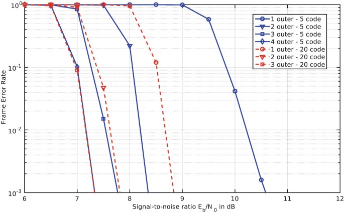
Example for complexity shifting in a double-iterative MIMO-BICM receiver by varying the number of outer loop and channel decoder iterations
Fig. 8 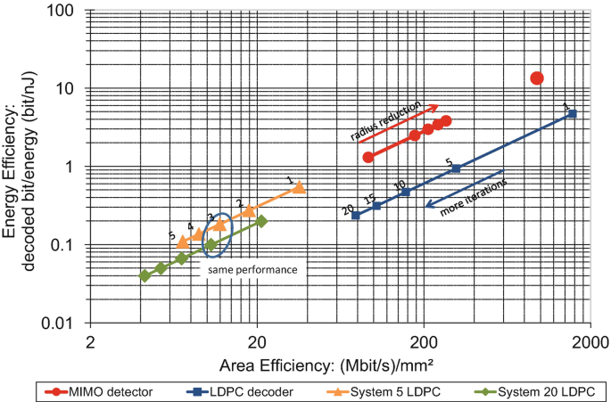
Implementation efficiency of MIMO detector, WiMax/WiFi LDPC decoder, and two system configurations using the efficiency metrics from [25]
-
Shifting of error correction capability between components: Typically, MIMO detector and channel decoder are designed and implemented independently of each other. The MIMO transmission scheme provides a large data rate but has no error correction abilities. The error correction capability is solely provided by the channel code to improve the error rate performance of the transmission system. From a system point of view, the MIMO detector does not work on completely independent data as there are dependencies from the overlaying channel code. However, this diversity cannot be exploited by the detector as the channel interleaver hides the code structure from the detector and because most channel code constraints span over many MIMO detection vectors. Kienle [24] introduced a small block code in each MIMO detection vector in order to generate a small diversity gain in the MIMO detector while simplifying the outer channel code to keep the overall coding rate constant. While this approach targeted the decoding complexity, it can also be used to increase the error resilience of the MIMO detector. Each parity check in one MIMO vector improves the error correction capabilities of the detector. On a system level, the diversity gain can be split between detector and decoder dynamically, thus, allowing the system to react dynamically to changing hardware error rates. The only drawback of this approach is that the diversity separation has to be done on the transmitter side, which causes a higher latency.


3 Approximate DRAM
Some communication systems require large data block sizes that cannot be stored in on-chip memories (SRAMs) anymore. In this case data has to be stored externally in DRAMs. Thus, in the following we shift our focus on DRAMs.
Approximate DRAM is a new concept that adapts the idea of approximate computing to DRAMs [23, 30]. Approximate DRAM exploits this fact by lowering the refresh frequency (reducing vendor guardbands) or even disable the refresh completely and accepting the risk of data errors. The underlying motivation for an Approximate DRAM is the increasing power consumption and performance penalty caused by unavoidable DRAM refresh commands. The authors of [29] and [1] predicted that 40–50% of the power consumption of future DRAM devices will be caused by refresh commands. Moreover, 3D integrated DRAMs like Wide I/O or HMC worsen the scenario with respect to increased cell leakage, due to the much higher temperature. Therefore, the refresh frequency needs to be increased accordingly to avoid retention errors [37].
The characteristic refresh parameters of DRAMs, listed in datasheets, are very pessimistic due to the high process margins added by the vendors to ensure correct functionality under worst-case conditions and most important a high yield [28]. Thus, the DRAM refresh rate recommended by the vendors and JEDEC (t REF = 64 ms) adds a large guardband, as shown in Fig. 9.

Qualitative retention error behavior of DRAMs
As mentioned before many applications like wireless systems have an inherent error resilience that tolerates these errors and therefore, refresh power often can be reduced with a minimal loss of the output quality.
Figure 9 qualitatively shows the retention error behavior over time and the design space for Approximate DRAM. The sphere around the curve represents the process variation, Variable Retention Times (VRT), and Data Pattern Dependencies (DPD). In general, we have two key parameters for Approximate DRAM: The data lifetime and the application robustness. Both parameters lead to three possibilities in this design space:
-
Refresh can be switched off if the data lifetime is smaller than the actual required refresh period.
-
Refresh can be turned off if the data lifetime is larger than the required refresh period and the application provides resilience to the resulting number of errors at this working point.
-
If the application only provides a maximal robustness the refresh rate is configured according to the resulting working point.
The reliability-energy trade-off for Approximate DRAMs can be explored only by using fast and accurate retention error-aware DRAM models.
In [39] we developed such a model that is usable in full system level simulations. The model was calibrated to the measurement results of DDR3 DRAM devices. A measurement statistic is shown in Fig. 10. Here we measured 40 identical 4 Gbit DDR3 chips from the same vendor. Each single device has been measured ten times at four different temperatures and five retention times, resulting in a total of 8000 measurement points. We plot the retention times versus the normalized and averaged number of errors obtained during each measurement step. The bars mark the minimum and the maximum measured number of errors. We find here a quite prominent variation in the order of 20% (max. number of errors), which shows a large temperature dependency. This needs to be considered as realistic guardband in approximate computing platforms utilizing the Approximate DRAM approach (cf. the sphere in Fig. 9). Additionally, the figure shows a histogram of the absolute number of bit errors (between 1 ⋅ 106 and 4 ⋅ 106) measured at the data point with 100s retention time and a temperature of 25 ∘C.

Retention error measurements of 40 4 Gbit DRAM Devices with different temperatures
Figure 11 shows our closed-loop simulation flow for investigations on Approximate DRAM. It is based on SystemC Transaction Level Models (TLM) for fast and accurate simulation. This simulation loop uses the modular DRAMSys framework [21] and consists of four key components: DRAM and core models [21], a DRAM power model [5], thermal models [38], and the aforementioned DRAM retention error model. The remaining models are shortly introduced in the following:
-
DRAM and Core Models: The DRAM model of the framework is based on a DRAM specific TLM protocol called DRAM-AT [20]. Due to TLM’s modular fashion several types of DRAM and controller configurations can be modeled. For modeling the cores the gem5 simulator is used [2]. We developed a coupling between gem5 and SystemC to be able to integrate this powerful research platform in our simulation loop [19].
-
DRAM Power Model: Since DRAMs contribute significantly to the power consumption of today’s systems [9, 27], there is a need for accurate power modeling. For our framework we use DRAMPower [4, 5], which uses either parameters from datasheets, estimated via DRAMSpec [33] or measurements to model DRAM power.
-
Thermal Model: 3D packaging of systems like Wide I/O DRAM starts to break down the memory and bandwidth walls. However, this comes at the price of increased power density and less horizontal heat removal capability of the thinned dies. Therefore, we integrated the thermal simulator 3D-ICE [38] in a SystemC wrapper [18] that is included in our closed-loop simulation for Approximate DRAM analysis.

Simulation Framework for Approximate DRAM Explorations and Reliability Management in SoCs
In a detailed case study [22] we used the presented simulation framework (Fig. 11) to investigate the influence of Approximate DRAM on three different applications. We achieved in average a more than 10% decrease of the total energy consumption.
4 Conclusions
Technology scaling is leading to a point where traditional worst-case design is no longer feasible. In this chapter, we presented a new methodology for the design of dependable wireless systems. We combined cross-layer reliability techniques to treat hardware errors with the least possible overhead leading to a high energy efficiency. This methodology enables efficient trade-offs between communications performance, throughput, and energy efficiency. However, the exact trade-off depends on the real application requirements, which was not in the focus of this work. Application-specific resilience actuators together with low-level techniques offer the ability to respond to the changing requirements on reliability and quality-of-service. We illustrated our new methodology on a state-of-the-art generic double-iterative MIMO-BICM receiver which belongs to the most complex systems in modern communication standards.
We identified dynamic resilience actuators on all layers of abstraction. Each actuator offers a trade-off between communications performance, implementation performance (throughput, power), and error resilience. Any actuator which trades off communications performance for throughput, e.g., the sphere radius, can be reused to increase the error resilience, when combined with a reduction of the clock frequency. Throughput and error resilience are, thus, closely related. As we have shown, algorithmic resilience actuators offer a great potential for dynamic trade-offs between communications performance, implementation performance, and error resilience. This work emphasizes the strong mutual dependencies between these three design metrics in a wireless receiver.
When the requirement in communication systems on data block sizes exceeds the capacities of the on-chip memories (SRAMs), external memories, such as DRAMs, have to be used. To reduce their impact on energy and performance we exploited the concept of Approximate DRAM. However, this comes at the cost of reduced reliability. For the exploration of approximate DRAMs we introduced a holistic simulation framework that includes an advanced DRAM retention error model. This model is calibrated to real measurements of recent DRAM devices. Finally, we demonstrated using the holistic simulation platform that the impact of Approximate DRAM on the quality (QoS or QoR) is negligible while saving refresh energy for three selected applications.
References
Bhati, I., Chishti, Z., Lu, S.L., Jacob, B.: Flexible auto-refresh: Enabling scalable and energy-efficient DRAM refresh reductions. In: Proceedings of the 42nd Annual International Symposium on Computer Architecture, pp. 235–246. ACM, New York (2015)
Binkert, N., Beckmann, B., Black, G., Reinhardt, S.K., Saidi, A., Basu, A., Hestness, J., Hower, D.R., Krishna, T., Sardashti, S., Sen, R., Sewell, K., Shoaib, M., Vaish, N., Hill, M.D., Wood, D.A.: The gem5 simulator. SIGARCH Comput. Archit. News 39(2), 1–7 (2011). http://doi.acm.org/10.1145/2024716.2024718
Brehm, C., May, M., Gimmler, C., Wehn, N.: A case study on error resilient architectures for wireless communication. In: Proceedings of the Architecture of Computing Ssystems, pp. 13–24 (2012)
Chandrasekar, K., Akesson, B., Goossens, K.: Improved power modeling of DDR SDRAMs. In: 2011 14th Euromicro Conference on Digital System Design (2011). http://dx.doi.org/10.1109/DSD.2011.17
Chandrasekar, K., Weis, C., Li, Y., Akesson, B., Naji, O., Jung, M., Wehn, N., Goossens, K.: DRAMPower: Open-source DRAM power & energy estimation tool (2012). http://www.drampower.info
Das, S., Tokunaga, C., Pant, S., Ma, W.H., Kalaiselvan, S., Lai, K., Bull, D.M., Blaauw, D.T.: RazorII: in situ error detection and correction for PVT and SER tolerance. IEEE J. Solid State Circuits 44(1), 32–48 (2009). https://doi.org/10.1109/JSSC.2008.2007145
Designing Chips without Guarantees. IEEE Design & Test of Computers 27(5), 60–67 (2010). https://doi.org/10.1109/MDT.2010.105
Dixit, A., Wood, A.: The impact of new technology on soft error rates. In: Proceedings of the IEEE International Reliability Physics Symposium (IRPS) (2011). https://doi.org/10.1109/IRPS.2011.5784522
Farahini, N., Hemani, A., Lansner, A., Clermidy, F., Svensson, C.: A scalable custom simulation machine for the Bayesian confidence propagation neural network model of the brain. In: 2014 19th Asia and South Pacific Design Automation Conference (ASP-DAC), pp. 578–585 (2014). https://doi.org/10.1109/IRPS.2011.578452210.1109/ASPDAC.2014.6742953
Gimmler, C., Lehnigk-Emden, T., Wehn, N.: Low-complexity iteration control for MIMO-BICM systems. In: Proceedings of the IEEE 21th International Symposium on Personal, Indoor and Mobile Radio Communications PIMRC 2010. Istanbul (2010)
Gimmler-Dumont, C., Wehn, N.: A cross-layer reliability design methodology for efficient, dependable wireless receivers. ACM Trans. Embed. Comput. Syst. 13, 1–29 (2014)
Gimmler-Dumont, C., Brehm, C., Wehn, N.: Reliability study on system memories of an iterative MIMO-BICM system. In: Proceedings of the IFIP/IEEE International Conference on Very Large Scale Integration 2012 (2012)
Gimmler-Dumont, C., Kienle, F., Wu, B., Masera, G.: A system view on iterative MIMO detection: dynamic sphere detection versus fixed effort list detection. VLSI Design J. 2012, Article ID 826350 (2012). https://doi.org/10.1155/2012/826350
Gupta, P., Agarwal, Y., Dolecek, L., Dutt, N., Gupta, R.K., Kumar, R., Mitra, S., Nicolau, A., Rosing, T.S., Srivastava, M.B., Swanson, S., Sylvester, D.: Underdesigned and opportunistic computing in presence of hardware variability. IEEE Trans. Comput. Aided Design Integr. Circuits Syst. 32(1), 8–23 (2013). https://doi.org/10.1109/TCAD.2012.2223467
Henkel, J., Bauer, L., Becker, J., Bringmann, O., Brinkschulte, U., Chakraborty, S., Engel, M., Ernst, R., Hartig, H., Hedrich, L., et al.: Design and architectures for dependable embedded systems. In: 2011 Proceedings of the 9th International Conference on Hardware/Software Codesign and System Synthesis (CODES+ ISSS), pp. 69–78. IEEE, Piscataway (2011)
Herkersdorf, A., Aliee, H., Engel, M., Glaß, M., Gimmler-Dumont, C., Henkel, J., Kleeberger, V.B., Kochte, M.A., Kühn, J.M., Mueller-Gritschneder, D., Wehn, N., et al.: Resilience articulation point (RAP): cross-layer dependability modeling for nanometer system-on-chip resilience. Microelectr. Reliab. 54(6), 1066–1074 (2014)
Hochwald, B., ten Brink, S.: Achieving near-capacity on a multiple-antenna channel. IEEE Trans. Commun. 51(3), 389–399 (2003). https://doi.org/10.1109/TCOMM.2003.809789
Jung, M.: Icewrapper - a systemC wrapper for 3D-ICE (2015). http://www.uni-kl.de/3d-dram/tools/icewrapper/
Jung, M., Wehn, N.: Coupling gem5 with systemC TLM 2.0 virtual platforms. In: gem5 User Workshop, International Symposium on Computer Architecture (ISCA). Portland (2015)
Jung, M., Weis, C., Wehn, N., Chandrasekar, K.: TLM modelling of 3D stacked wide I/O DRAM subsystems: a virtual platform for memory controller design space exploration. In: Proceedings of the 2013 Workshop on Rapid Simulation and Performance Evaluation: Methods and Tools, RAPIDO ’13, pp. 5:1–5:6. ACM, New York (2013). http://doi.acm.org/10.1145/2432516.2432521
Jung, M., Weis, C., Wehn, N.: DRAMSys: A flexible DRAM subsystem design space exploration framework. IPSJ Trans. Syst. LSI Design Methodol. 8, 63–74 (2015)
Jung, M., Zulian, E., Mathew, D., Herrmann, M., Brugger, C., Weis, C., Wehn, N.: Omitting refresh - A case study for commodity and wide I/O DRAMs. In: 1st International Symposium on Memory Systems (MEMSYS 2015). Washington (2015)
Jung, M., Mathew, D.M., Weis, C., Wehn, N.: Efficient reliability management in SoCs - An approximate DRAM perspective. In: 21st Asia and South Pacific Design Automation Conference (ASP-DAC) (2016)
Kienle, F.: Low-Density MIMO Codes. In: Proceedings of the 5th International Symposium on Turbo Codes and Related Topics, pp. 107–112. Lausanne (2008)
Kienle, F., Wehn, N., Meyr, H.: On complexity, energy- and implementation-efficiency of channel decoders. IEEE Trans. Commun. 59(12), 3301–3310 (2011). https://doi.org/10.1109/TCOMM.2011.092011.100157
Kleeberger, V., Gimmler-Dumont, C., Weis, C., Herkersdorf, A., Mueller-Gritschneder, D., Nassif, S., Schlichtmann, U., Wehn, N.: A cross-layer technology-based study of the impact of memory errors on system resilience. IEEE Micro 33(4), 46–55 (2013)
Krueger, J., Donofrio, D., Shalf, J., Mohiyuddin, M., Williams, S., Oliker, L., Pfreundt, F.J.: Hardware/software co-design for energy-efficient seismic modeling. In: Proceedings of the 2011 International Conference for High Performance Computing, Networking, Storage and Analysis (SC), pp. 1–12 (2011)
Lee, D., Kim, Y., Pekhimenko, G., Khan, S., Seshadri, V., Chang, K., Mutlu, O.: Adaptive-latency DRAM: Optimizing DRAM timing for the common-case. In: 2015 IEEE 21st International Symposium on High Performance Computer Architecture (HPCA), pp. 489–501 (2015). https://doi.org/10.1109/HPCA.2015.7056057
Liu, J., Jaiyen, B., Veras, R., Mutlu, O.: RAIDR: Retention-aware intelligent DRAM refresh. In: Proceedings of the 39th Annual International Symposium on Computer Architecture, ISCA ’12, pp. 1–12. IEEE Computer Society, Washington (2012). http://dl.acm.org/citation.cfm?id=2337159.2337161
Lucas, J., Alvarez-Mesa, M., Andersch, M., Juurlink, B.: Sparkk: Quality-scalable approximate storage in DRAM. In: The Memory Forum (2014). http://www.redaktion.tu-berlin.de/fileadmin/fg196/publication/sparkk2014.pdf
May, M., Alles, M., Wehn, N.: A case study in reliability-aware design: A resilient LDPC code decoder. In: Proceedings of the Design, Automation and Test in Europe DATE ’08, pp. 456–461. Munich (2008)
Mitra, S., Brelsford, K., Kim, Y.M., Lee, H.H.K., Li, Y.: Robust system design to overcome CMOS reliability challenges. IEEE J. Emer. Sel. Topics Circuits Syst. 1(1), 30–41 (2011). https://doi.org/10.1109/JETCAS.2011.2135630
Naji, O., Weis, C., Jung, M., Wehn, N., Hansson, A.: A high-level DRAM timing, power and area exploration tool. In: Embedded Computer Systems Architectures Modeling and Simulation (SAMOS) (2015)
Nazar, G.L., Gimmler, C., Wehn, N.: Implementation comparisons of the QR decomposition for MIMO detection. In: Proceedings of the 23rd Symposium on Integrated Circuits and System Design (SBCCI ’10), pp. 210–214. ACM, New York (2010). https://doi.org/10.1145/1854153.1854204
Nowka, K., Nassif, S., Agarwal, K.: Characterization and design for variability and reliability. In: Proceedings of the IEEE Custom Integrated Circuits Conference CICC 2008, pp. 341–346 (2008). https://doi.org/10.1109/CICC.2008.4672092
Qian, W., Li, X., Riedel, M., Bazargan, K., Lilja, D.: An architecture for fault-tolerant computation with stochastic logic. IEEE Trans. Comput. 60(1), 93–105 (2011). https://doi.org/10.1109/TC.2010.202
Sadri, M., Jung, M., Weis, C., Wehn, N., Benini, L.: Energy optimization in 3D MPSoCs with Wide-I/O DRAM using temperature variation aware bank-wise refresh. In: Design, Automation and Test in Europe Conference and Exhibition (DATE), 2014, pp. 1–4 (2014). https://doi.org/10.7873/DATE2014.294
Sridhar, A., Vincenzi, A., Ruggiero, M., Brunschwiler, T., Atienza, D.: 3D-ICE: Fast compact transient thermal modeling for 3D ICs with inter-tier liquid cooling. In: Proceedings of the IEEE International Conference on Computer-Aided Design ICCAD 2010 (2010)
Weis, C., Jung, M., Ehses, P., Santos, C., Vivet, P., Goossens, S., Koedam, M., Wehn, N.: Retention time measurements and modelling of bit error rates of WIDE I/O DRAM in MPSoCs. In: Proceedings of the IEEE Conference on Design, Automation & Test in Europe (DATE). European Design and Automation Association (2015)
Author information
Authors and Affiliations
Corresponding author
Editor information
Editors and Affiliations
Rights and permissions
Open Access This chapter is licensed under the terms of the Creative Commons Attribution 4.0 International License (http://creativecommons.org/licenses/by/4.0/), which permits use, sharing, adaptation, distribution and reproduction in any medium or format, as long as you give appropriate credit to the original author(s) and the source, provide a link to the Creative Commons license and indicate if changes were made.
The images or other third party material in this chapter are included in the chapter's Creative Commons license, unless indicated otherwise in a credit line to the material. If material is not included in the chapter's Creative Commons license and your intended use is not permitted by statutory regulation or exceeds the permitted use, you will need to obtain permission directly from the copyright holder.
Copyright information
© 2021 The Author(s)
About this chapter

Cite this chapter
Weis, C., Gimmler-Dumont, C., Jung, M., Wehn, N. (2021). Design of Efficient, Dependable SoCs Based on a Cross-Layer-Reliability Approach with Emphasis on Wireless Communication as Application and DRAM Memories. In: Henkel, J., Dutt, N. (eds) Dependable Embedded Systems . Embedded Systems. Springer, Cham. https://doi.org/10.1007/978-3-030-52017-5_18
Download citation
DOI: https://doi.org/10.1007/978-3-030-52017-5_18
Published:
Publisher Name: Springer, Cham
Print ISBN: 978-3-030-52016-8
Online ISBN: 978-3-030-52017-5
eBook Packages: EngineeringEngineering (R0)