
Abstract
The fatigue life of prestressed concrete beams, subjected to cyclic bending, mainly depends on the fatigue behaviour of the embedded prestressing strands. An evaluation of international fatigue test results revealed a reduced fatigue life of embedded strands in prestressed concrete beams compared to single strands in air. The reduced fatigue life can be explained by specific influences and fatigue processes caused by the built-in conditions of strands. Due to the lack of basic understanding, systematic investigations are currently carried out to identify, quantify and describe different influencing parameters and fatigue processes as well as to better understand and determine the fatigue behaviour of strands in pre-tensioned concrete beams. In this article, the experimental investigations regarding the fatigue life of strands embedded in concrete are presented. Within cyclic uniaxial tensile tests on strands in air and strands embedded in concrete, the influence of fretting fatigue processes and friction stresses between the outer wires of strands and the surrounding concrete was determined.
1 Introduction
Precast prestressed concrete beams, which are used as bridge girders (Fig. 1), are subjected to cyclic loads caused by high and heavy traffic. Consequently, the fatigue resistance of such beams is of major importance within the design and the life-cycle assessment of such bridges.

Exemplary precast prestressed concrete bridge girders
The fatigue behaviour of prestressed concrete beams, subjected to cyclic bending loads, depends primarily on the fatigue of the embedded prestressing strands. In current code provisions, e.g. in EC2 [1] and MC2010 [2], the fatigue life of strands is described by S–N curves only based on the relationship between stress range in the strands and number of load cycles until failure. However, the fatigue life of strands is affected by specific influences and fatigue processes due to built-in conditions of strands in prestressed concrete beams [3]. While many research works focused on influences within post-tensioned concrete beams, e.g. fretting corrosion effects due to friction between strands and duct, fatigue phenomena in pre-tensioned concrete beams have not been studied in detail so far.
In order to evaluate the fatigue life of pre-tensioned concrete structures, international fatigue test results of pre-tensioned concrete beams and single strands were summarised in a database at iBMB, Division of Concrete Construction of the TU Braunschweig (iBMB database). The evaluation of test results revealed a significant difference between fatigue tests with embedded strands in concrete beams and cyclic tensile tests with single strands in air. Besides, a large part of the test results of prestressed concrete beams - especially with small stress ranges in strands and high numbers of load cycles - indicates a lower fatigue life compared to the S–N curves according to EC2 [1] and MC2010 [2]. Due to the lack of basic understanding on the fatigue life of prestressing strands, systematic investigations are carried out to identify, quantify and describe different influencing parameters and fatigue processes. In this article, the experimental investigations and results regarding the influence of concrete embedment of strands are presented.
2 Fatigue of prestressing strands
2.1 Fatigue database
The fatigue life of strands was investigated in numerous fatigue tests on single strands tested in air (e.g. [4]) as well as on prestressed concrete beams ([5,6,7,8,9,10,11,12,13,14,15,16,17,18,19]), which are gathered in the iBMB database. The fatigue test results in the database are evaluated in Fig. 2 in comparison to the normative S–N curve according to EC2/MC2010 ([1, 2]). Here, the fatigue failure is defined as the first indication of damage, which is usually the first wire break of a strand. It can be noticed that the normative S–N curve (for strands in pre-tensioned concrete structures) safely includes the fatigue test results of the single strands tested in air (from [4]) and can be considered as a lower bound approach for such tests.

Fatigue test results of prestressed concrete beams and single strands in air in comparison to the S–N curve according to EC2/MC2010 (double-logarithmic scale)
In contrast, the normative S–N curve does not reflect the experimental fatigue life of strands in pre-tensioned concrete beams. Even though a similar fatigue life of single strands and embedded strands in beams at stress ranges greater than 200 N/mm2 can be noticed, at stress ranges less than 200 N/mm2 the fatigue life of strands in beams is, in many cases, significantly lower than the fatigue life of single strands and thus lower than the fatigue life according to the normative S–N curve. The reduced fatigue life of embedded strands was confirmed by an own fatigue test on a pre-tensioned concrete beam (Fig. 3, cf. [5]) and can be explained by basic influences and fatigue processes (cf. Sect. 2.2) as well as specific influences caused by the built-in conditions of strands (cf. Sect. 2.3).

Fatigue test of a prestressed concrete beam at iBMB (after failure)
2.2 Basic influences and fatigue processes
The fatigue behaviour of strands depends on many influencing parameters, which can lead to accelerated fatigue processes. The main influences on the fatigue behaviour of strands (in concrete) are summarized in Fig. 4.

Basic influences on the fatigue behaviour of strands
Basically, the fatigue behaviour of prestressing steel depends on production (e.g. drawing process) and material parameters (e.g. composition of steel) as well as type (e.g. strands, wires or bars) and geometry (e.g. diameter). These parameters can be summarised as inherent influences, which define the basic fatigue behaviour of strands. Previous own fatigue tests (iBMB/MPA-BS) are depicted in Fig. 5 in comparison to the available datasets in the iBMB database. A reduction of the fatigue life of prestressing strands in comparison to prestressing wires is evident, which signifies the effects of inner friction processes caused by the contact pressure between the twisted outer wires of strands (Fig. 5).

Comparison of fatigue test results of single strands and wires tested in air (double-logarithmic scale)
Furthermore, a comparison between the fatigue behaviour of strands in prestressed concrete beams and strands in air shows the effects of fretting fatigue processes and friction stresses between the outer wires of strands and the surrounding concrete. Fretting fatigue results from rubbing actions due to repeated relative motion between strands and concrete in the vicinity of concrete cracks. In this area, the outer wires of the strands are able to untwist so that a lateral pressure on the wires is generated (Fig. 6). Here, the concrete strength as well as fine/coarse aggregate types are possible parameters affecting the fatigue strength of the embedded strands. In prestressed concrete beams subjected to cyclic bending loads, this lateral pressure between steel and concrete adjacent to cracks is additionally increased by the deflection of beams.

Friction processes at strands in concrete [3]
Investigation of the effect of these influences on the fatigue behaviour of embedded strands is of great interest for the prediction of the fatigue life, especially with regard to the evaluation in Sect. 2.1. To examine and quantify the influence of concrete embedment on the fatigue life of strands, systematic tensile fatigue tests on strands with and without concrete embedment were conducted, which are presented and discussed in the following.
Load-dependent influences, including e.g. varying stress ranges during the fatigue life, are not considered within this article.
2.3 Specific influences due to built-in conditions of strands
Based on previous investigations on the fatigue behaviour of prestressed concrete beams (and of prestressing strands tested in air), the following main conclusions are drawn regarding different influences on the fatigue of strands [3]:
The fatigue life of strands in prestressed concrete beams depends on the ratio between reinforcement steel and prestressing steel (e.g. [14]). Even with a slight increase of the reinforcement, a significant increase in fatigue life could be observed in fatigue tests on pre-tensioned concrete beams. This is due to the improved bond properties of reinforcement steel, which limit crack widths and deformations. Additionally, prestressing steel stresses and stress ranges are reduced.
Concrete cracks and the progressive damage of the bond between strands and concrete adjacent to cracks resulting from cyclic loading influence the fatigue behaviour of strands (e.g. [8, 11]). The fatigue life of embedded strands can be reduced due to increased steel stresses (and stress ranges) in the vicinity of concrete cracks as well as bending stresses in the strands due to the increasing beam deflections [21].
After fatigue tests on pre-tensioned concrete beams in [5, 22], corrosion products were found on the surface of prestressing strands. Two mechanisms need to be distinguished here. In some cases, planar corrosion products were observed on the strand surface in the vicinity of concrete cracks which might be caused by an electro-chemical process. In other cases, the corrosion occurred in a very small zone (see Fig. 13 left), indicating a presence of fretting actions in the contact zone between strands and concrete, which is also known as fretting corrosion resulting in fretting fatigue (analogously to post-tensioned concrete beams, cf. [23, 24]). As a result of these fretting actions and corrosion products, in some tests, the fatigue life was considerably reduced compared to tests on single strands with equal stress ranges [11].
3 Experimental investigations
3.1 Experimental programme
The experimental investigations described in this paper focus on the different fatigue life of strands in air and strands embedded in concrete as well as the influence of different aggregate shape (round and angular). It was supposed that angular aggregate (grit) results in higher friction between strands and concrete in comparison to round aggregate (gravel). These experimental investigations aim to gain basic knowledge about the influence of concrete embedment and mixture on the fatigue behaviour of embedded strands, which can subsequently be transferred to the fatigue behaviour of pre-tensioned concrete beams.
3.2 Specimens and test setup
Initially, cyclic uniaxial tensile tests on strands in air were conducted with different stress ranges as a reference (test series “DSV”, Table 1). In comparison to these tests, 14 modified cyclic tensile tests on strands embedded in concrete were performed (test series “mDSV-B”, Table 2). Within the tests, the stress range in the strands as well as the aggregate of concrete (round and angular) were varied.
The dimensions of specimens and the test setup are shown in Fig. 7. The total length of the strands was chosen to 950 mm, resulting in a free length of three times the pitch length (based on a grip length of 180 mm at both ends). The strands were embedded in a cylindrical concrete body on a length of 300 mm with a diameter of 50 mm. Details of the strands and the concrete are described in Sect. 4.

Test setup of cyclic tensile tests on strands in air (left) and modified cyclic tensile tests on strands embedded in concrete (right)
The strands were installed in a hydraulic pulsator testing machine and were initially stressed to the minimum cyclic stress level, based on the predefined stress range and an upper cyclic stress level of 70% of the ultimate tensile strength of the strands. Afterwards the concrete was cast in a cylindrical form around the strand. The cyclic loading was started with a frequency of 7 Hz (420 cycles/min) seven days after concrete casting. The cylindrical form around the concrete was not removed during the test to maintain transverse pressure on concrete for comparable stress conditions as in prestressed concrete structures. The tests were stopped automatically at the time of first wire break. Only two tests (mDSV-B-150-2 and mDSV-B-100-1) were stopped without failure after 25 million (about 41 days) and 100 million cycles (about 165 days) respectively.
4 Materials
4.1 Prestressing strands
In all tests, a seven-wire strand of the grade St1660/1860 with a diameter of 12.5 mm (0.5”) from the same production batch was used. The geometrical and mechanical properties, determined on six strands according to [25], are summarised in Table 3. The experimental stress–strain relationship is shown in Fig. 8.

Stress-strain relationship of strands
4.2 Concrete
The concrete body was made of normal strength concrete C50/60, which on the one hand is often used in precast prestressed concrete girders and on the other hand, corresponds to currently conducted fatigue tests on pre-tensioned concrete beams at iBMB. The coarse aggregate of concrete was varied between gravel (2/8 mm) and basalt grit (2/5 mm) (Fig. 9). The corresponding concrete mixtures are listed in Tables 4 and 5. For each test, 12 concrete cylinders with a height to diameter ratio of h/d = 300/150 mm were prepared to determine the compressive strength, modulus of elasticity and tensile splitting strength at a concrete age of 7 days (beginning of the cyclic loading) as well as the compressive strength at 28 days. Note that some fatigue tests were conducted simultaneously so that the mechanical properties are the same. The results are summarised in Table 2.

Different coarse aggregate: Gravel (left) and basalt grit (right)
5 Results
5.1 Failure mode
After the tests the concrete was removed and the origin of wire breaks was localised by digital microscope images of the fractured wire surfaces (see appendix). The types (and origins) of wire breaks in the tests are included in Tables 1 and 2, generally differentiated in:
Type I: Fracture of an outer wire initiated in the outer surface of the wire (in the free length outside the concrete)
Type II: Fracture of an outer wire initiated in the contact zone to an adjacent outer wire
Type III: Fracture of an outer wire initiated in the contact zone to the centre wire
Type IV: Fracture of the centre wire (initiated in the contact zone to an adjacent outer wire)
Type V: Fracture of an outer wire initiated in the contact zone to the surrounding concrete
The different types of failure are visualized in Fig. 10. Type I describes a failure without contact to another wire or concrete and may be considered as a true material fatigue failure. The types II to IV describe fatigue failures due to fretting caused by rubbing actions due to repeated relative motion between two adjacent wires. Within these types a distinction was made between fractures located in the free length of the strand (a) or in the area of concrete (b), corresponding to type IIa/IIb, IIIa/IIIb and IVa/IVb. Type V is a specific fatigue failure of strands embedded in concrete caused by friction stresses and fretting actions between strand and concrete resulted from repeating reopening of concrete cracks during fatigue loading in combination with the restricted twisting ability in the vicinity of the concrete cracks.

Schematic description of different types of failure
Within the tests no failure was caused due to clamping. All failures outside the concrete occurred at a distance from the clamping (and from the steel pipe, c.f. Fig. 7) of at least twice the strand diameter.
The types II and V are the most common failures of embedded strands. Specimens subjected to high stress ranges (approximately > 300 N/mm2) usually failed due to fracture of an outer wire in the contact zone to an adjacent outer wire in the free length outside the concrete (type IIa). In contrast, specimens subjected to lower stress ranges (approximately ≤ 300 N/mm2) often failed due to failure of an outer wire in the contact zone to the surrounding concrete (type V) or failure of an outer wire in the contact zone to an adjacent outer wire in the area of concrete (type IIb). The latter is caused by increased friction between two (outer) wires due to intruded fines of concrete. A relationship between failure mode and aggregate type could not be determined.
Based on the distribution of concrete cracks and the location of wire breaks in the concrete body, illustrated in Fig. 11, it is visible that nearly all wire breaks in the concrete body occurred near concrete cracks.

Distribution of concrete cracks (over the circumference of the concrete body) and location of wire breaks
5.2 Failure process
Moreover, the fractured wire surface of all strands was analysed with regard to a relationship between characteristics of wire surface and failure mode indicating damage mechanisms and failure processes. A typical fractured wire surface caused by fatigue loading is characterized by
the initiation surface as the origin of the wire break,
the fatigue fracture surface indicating crack propagation and
the brittle fracture surface (Fig. 12 left).
Fig. 12 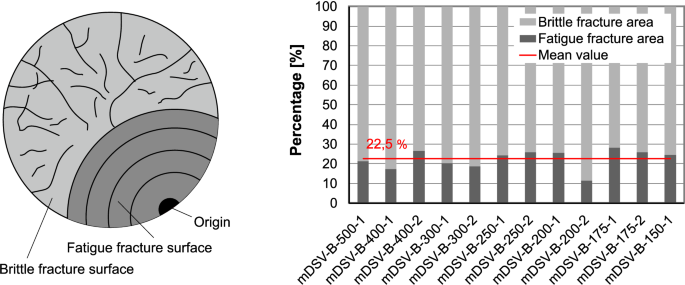
Characteristic fracture surface of wires caused by fatigue (left) and evaluation of fractured wire surfaces of test specimens (right)

Initially, the fatigue fracture area was evaluated in relation to the total cross-sectional area of the fractured wires (Fig. 12 right), showing an average fatigue fracture area of about 22.5%. However, the fatigue fracture area is neither correlated to the stress range (or fatigue life) nor to the fatigue failure type.
The value of 22.5% depends rather on the upper cyclic stress level of 70% of the ultimate tensile strength of the strands (corresponds to 0.7·1882 N/mm2 = 1317 N/mm2). Due to the progressive fatigue fracture, the effective cross-sectional area of the strand gradually decreases. As a result, the steel stress increases with a factor of 1/(1 − 0.225) = 1.29 to a value of 1.29 × 1317 N/mm2 = 1699 N/mm2 which corresponds approximately to the yield strength of the strands, resulting in a brittle fracture of the wire. This implies that the upper cyclic stress level might influence the fatigue fracture area.
Nevertheless, the origins of fractured wire surfaces of the failure types V and IIb are attributed to different damage mechanisms (Fig. 13). The origin of failure type V is characterized by fretting corrosion products in a small area located at a concrete crack. In contrast, the failure type IIb occurs parallel to the friction surface between the outer wires, where only few corrosion products can be detected. Here, reduced fatigue life is a result of higher friction stresses due to the fines of concrete between the wires.

Exemplary fatigue fracture surfaces of wires failed by type V (left: mDSV-B-300-1; middle left: mDSV-B-250-1) and by type IIb (middle right: mDSV-B-175-1; right: mDSV-B-175-2)
5.3 Fatigue life
The fatigue test results of strands in air and strands embedded in concrete are evaluated in an S–N diagram (Fig. 14). The results show that (similar to previous test results in Fig. 5) the fatigue life of strands in air and embedded in concrete is similar at stress ranges above 300 N/mm2. Here, the surrounding concrete does not lead to a reduction in fatigue life of strands, meaning that the basic fatigue behaviour of strands dominates the fatigue life. This is confirmed by the failure in the free length of the strand outside the concrete (see failure modes in Sect. 5.1). At stress ranges of about 300 N/mm2 and less, no fatigue failure of strands in air was observed, indicating an endurance limit of the strands. In contrast, the strands embedded in concrete also failed at stress ranges substantially less than 300 N/mm2. Only at a stress range of 100 N/mm2, no failure occurred within 108 load cycles (test specimen mDSV-B-100-1) but no actual endurance limit of embedded strands is observed. The reduced fatigue life of embedded strands at small stress ranges points out that the fatigue of strands in the low stress range, long life region is strongly influenced by increased friction stresses and fretting actions in concrete.

Fatigue test results of strands in air and strands embedded in concrete: Derived log-bilinear S–N average curves (top) and derived log-bilinear S–N envelope curve (bottom) (double-logarithmic scale)
As a result, the following (log-bilinear) S–N envelope curve was derived, divided into the high stress range, short life region (Eq. (1)) and the low stress range, long life region (Eq. (2)):
Based on the terminology according to EC2 [1] and MC2010 [2], this corresponds to values of k1 = 3.0, k2 = 9.0 and Δσ (N = 106) = 185 N/mm2. It should be noted that although this S–N curve reflects a lower bound approach for the fatigue of single strands in concrete, it does not cover the results on pre-tensioned concrete beams (see Sect. 5.4). The tests provide an assessment of the influence of the concrete embedment on the fatigue of single strands.
The original assumption that the angular aggregate has an unfavourable effect on the fatigue life of embedded strands (caused by higher friction) could not be confirmed. On the contrary, the tests indicated a lower fatigue strength of strands embedded in concrete with round aggregate. Possible reasons are the slightly higher concrete strength (Table 2) or the higher content of fines (cement etc.) of the concrete with round aggregate (Tables 4 and 5).
5.4 Evaluation and discussion
In previous research as well as in current design codes, it was assumed that the fatigue life of strands in pre-tensioned concrete beams is comparable to that of single strands tested in air. Based on the presented investigations and results, this assumption could only be confirmed in the high stress range, short life region.
It is shown that the fatigue life of single strands with and without concrete embedment as well as of strands in concrete beams is similar at high stress ranges in the strands (Fig. 15). This high stress range, short life region shows a normal scatter of test results, so that the fatigue life of strands can be estimated very well. In contrast, at small stress ranges in the strands, which usually occur in prestressed concrete beams e.g. in bridges, the fatigue life of strands embedded in concrete is significantly reduced compared to strands in air. In this stress region, increased friction stresses and fretting actions in concrete become more decisive for the fatigue life. Similar results with regard to the reduction of fatigue life depending on the applied stress range are known from tests with strands in air and strands in post-tensioned concrete beams (c.f. [3], [20]).

Fatigue test results of strands in air, strands embedded in concrete and prestressed concrete beams (double-logarithmic scale)
The selected test setup and testing procedure are generally applicable to indicate the influence of concrete embedment on the fatigue life of strands. However, the performed fatigue tests may be considered as a starting point to quantify and model the fatigue behaviour of embedded strands under consideration of different influences within further research. Considerable variation of fatigue resistance might be expected as a result of different inherent influences (according to Sect. 2.2).
Moreover, as shown in Fig. 15, the fatigue life of strands in concrete beams subjected to cyclic bending is further decreased compared to uniaxially loaded single strands embedded in concrete. Thus, further structural influences (according to Sect. 2.3), such as lateral pressure between steel and concrete and bending effects adjacent to cracks caused by deflection of beams, as well as design aspects such as the prestressing/reinforcement ratio have to be investigated within additional fatigue tests on modified cyclic tensile tests (e.g. on deflected strands in concrete) and on pre-tensioned concrete beams.
It is worth noting that only with test results containing both inherent and structural influence parameters, a reasonable fatigue design approach for the practical design and construction of pre-tensioned concrete beams can be derived. On this basis, an enhanced prediction accuracy of the fatigue life of pre-tensioned concrete beams and embedded strands is possible.
6 Conclusions and outlook
In this study, the fatigue life of prestressing strands embedded in concrete was investigated. Within cyclic tensile tests on strands in air (as a reference) and strands embedded in concrete, the influence of fretting fatigue processes and friction stresses between the outer wires of strands and the surrounding concrete was determined.
Based on the test results and discussion provided, the following conclusions can be drawn:
The fatigue life of strands in air and strands embedded in concrete is similar at high stress ranges above 300 N/mm2, meaning that the basic fatigue behaviour of strands dominates the fatigue life.
In contrast, no fatigue failure of strands in air was observed at stress ranges of about 300 N/mm2 and less, while embedded strands failed also at stress ranges substantially less than 300 N/mm2. Obviously, the influence of specific fatigue processes and damage mechanisms caused by the surrounding concrete, such as friction stresses and fretting actions, increases at lower stress ranges.
Based on the test results, a log-bilinear S–N envelope curve was derived, describing a lower bound relationship between stress range and fatigue life of single strands embedded in concrete.
The fatigue life of strands seems to be unaffected by the coarse aggregate of the surrounding concrete. But, the concrete strength and/or the content of fines in concrete might have an influence.
Microscopic investigations of the fractured wire surfaces were used to determine the origin and type of fatigue failures. While specimens subjected to high stress ranges usually failed due to fracture of an outer wire in the contact zone to an adjacent outer wire in the free length outside the concrete, specimens subjected to small stress ranges usually failed due to failure of an outer wire in the contact zone to the surrounding concrete or to an adjacent outer wire in the area of concrete.
Overall, this research indicates that the fatigue of strands is significantly influenced by specific fatigue processes resulting from the concrete embedment. In this study, only normal strength concrete with different coarse aggregate shapes was considered. In further research, the fatigue behaviour of embedded strands needs to be investigated with regard to latest developments in concrete technology considering mixtures e.g. with high content of fines and higher concrete strength values.
Beside the influence of concrete embedment, further structural influences, such as lateral pressure between steel and concrete and bending effects adjacent to cracks caused by deflection of beams, as well as design aspects such as the prestressing/reinforcement ratio are currently investigated within additional fatigue tests on modified cyclic tensile tests and on pre-tensioned concrete beams at iBMB, Division of Concrete Construction of TU Braunschweig.
The aim of these investigations is to derive a reasonable fatigue model for the practical design and construction of pre-tensioned concrete beams, which will allow an enhanced prediction accuracy of the fatigue life of pre-tensioned concrete beams and embedded strands.
References
European Committee for Standardization (CEN) EN 1992-1-1 (2004) Eurocode 2: design of concrete structures - part 1-1: general rules and rules for buildings, Brussels
Fédération Internationale du Béton (2013) fib model code for concrete structures 2010, Lausanne
Remitz J, Empelmann M (2018) Specific influences on fatigue life of prestressing steel. In: Proceedings of 12th Japanese German Bridge Symposium, Munich
Paulson Jr C, Frank KH, Breen JE (1983) A fatigue study of prestressing strand. Report No. 300-1, University of Texas at Austin, Bureau of Engineering Research
Remitz J, Empelmann M (2015) Ermüdungsfestigkeit von eingebauten Spanngliedern - Versuche an Spannbetonträgern. Bauingenieur 90(12):553–561
Ozell AM, Ardaman E (1956) Fatigue tests of pre-tensioned prestressed beams. ACI Struct J 28(4):413–424
Nordby GM, Venuti WJ (1957) Fatigue and static tests of steel strand prestressed beams of expanded shale concrete and conventional concrete. ACI Struct J 54(2):141–160
Ozell AM, Diniz JF (1958) Fatigue tests of prestressed concrete beams pretensioned with 1/2 inch strands. PCI J 3(1):79–88
Bate SCC (1962) An experimental study of strand in prestressed concrete beams under static and repeated loading. Proc Inst Civ Eng 23(4):625–638
Warner RF, Hulsbos CL (1964) Probable fatigue life of prestressed concrete beams part I - IV. Report No. 223.24C1-4, Lehigh University
Abeles PW, Brown II EI, Hu CH (1974) Fatigue resistance of under-reinforced prestressed beams subjected to different stress ranges. In: Abeles symposium - fatigue of concrete, ACI-Publication SP-41, pp 237–277
Rabbat BG, Kaar PH, Russel HG, Bruce RN Jr (1979) Fatigue tests of pretensioned girders with blanketed and draped strands. PCI J 24(4):88–114
Harajli MH, Naaman AE (1984) Deformation and cracking of partially prestressed concrete beams under static and cyclic fatigue loading. Report No. UMEE 84R1, University of Michigan, College of Engineering
Overman TR, Breen JE, Frank KH (1984) Fatigue behavior of pretensioned concrete girders. Report No. 300-2F, University of Texas at Austin, Center for Transportation Research
Bökamp H (1991) Ein Beitrag zur Spannstahlermüdung unter Reibdauerbeanspruchung bei teilweiser Vorspannung. Dissertation, RWTH Aachen, Germany
Muller JF, Dux PF (1992) Fatigue of prestressed concrete beams with inclined strands. Report No. CE 135, University of Queensland, Department of Civil Engineering
Rao C, Frantz GC (1995) Fatigue tests of 27-year-old prestressed concrete bridge box beams. PCI J 11(2):16–39
Hagenberger MJ (2004) Consideration of strand fatigue for load rating prestressed concrete bridges, PhD. Dissertation, University of Texas at Austin, USA
Grunert JP (2006) Zum Tragverhalten von Spannbetonfertigteilbalken aus Stahlfaserbeton ohne Betonstahlbewehrung, PhD. Dissertation, TU Braunschweig, Germany
Heeke G, Heinrich H, Maurer R (2019) Neue Erkenntnisse zur Ermüdungsfestigkeit von Spannbeton unter sehr hohen Lastwechselzahlen - Prognose der Lebensdauer. Beton- und Stahlbetonbau 114(4):242–254
Edwards AD, Picard A (1972) Fatigue characteristics of prestressing strand. Proc Inst Civ Eng 53(2):323–336
Heller BE (2003) Fatigue response of pretensioned concrete beams. MSc. thesis, University of Texas at Austin, USA
Empelmann M, Remitz J (2014) Ermüdungsverhalten von Spanngliedern mit nachträglichem Verbund. Beton- und Stahlbetonbau 109(11):760–770
Remitz J, Empelmann M (2018) Einfluss von Umlenkbelastungen auf die Ermüdung von Spanngliedern im nachträglichen Verbund. Beton- und Stahlbetonbau 113(8):579–588
DIN EN ISO 15630-3 (2011) Steel for the reinforcement and prestressing of concrete - test methods - part 2: prestressing steel; German version EN ISO 15630-3:2010, Berlin
Acknowledgements
Open Access funding provided by Projekt DEAL. The investigations presented in this paper were conducted at the iBMB, Division of Concrete Construction of the TU Braunschweig within a research project funded by the Deutsche Forschungsgemeinschaft (DFG, German Research Foundation) – Project number 351987113. The authors acknowledge the financial support.
Author information
Authors and Affiliations
Corresponding author
Ethics declarations
Conflict of interest
All authors declare that they have no conflict of interest.
Additional information
Publisher's Note
Springer Nature remains neutral with regard to jurisdictional claims in published maps and institutional affiliations.
Appendix
Appendix
See Figs. 16, 17, 18, 19, 20, 21, 22.

Fractured wire surface of specimen mDSV-B-500-1

Fractured wire surface of specimens mDSV-B-400-1 (left) and mDSV-B-400-2 (right)

Fractured wire surface of specimens mDSV-B-300-1 (left) and mDSV-B-300-2 (right)

Fractured wire surface of specimens mDSV-B-250-1 (left) and mDSV-B-250-2 (right)

Fractured wire surface of specimens mDSV-B-200-1 (left) and mDSV-B-200-2 (right)

Fractured wire surface of specimens mDSV-B-175-1 (left) and mDSV-B-175-2 (right)

Fractured wire surface of specimen mDSV-B-150-1
Rights and permissions
Open Access This article is licensed under a Creative Commons Attribution 4.0 International License, which permits use, sharing, adaptation, distribution and reproduction in any medium or format, as long as you give appropriate credit to the original author(s) and the source, provide a link to the Creative Commons licence, and indicate if changes were made. The images or other third party material in this article are included in the article's Creative Commons licence, unless indicated otherwise in a credit line to the material. If material is not included in the article's Creative Commons licence and your intended use is not permitted by statutory regulation or exceeds the permitted use, you will need to obtain permission directly from the copyright holder. To view a copy of this licence, visit http://creativecommons.org/licenses/by/4.0/.
About this article

Cite this article
Remitz, J., Empelmann, M. Cyclic tensile tests on prestressing strands embedded in concrete. Mater Struct 53, 53 (2020). https://doi.org/10.1617/s11527-020-01484-x
Received:
Accepted:
Published:
DOI: https://doi.org/10.1617/s11527-020-01484-x