
Abstract
Electric vehicles (EVs) are a promising solution to reduce the transportation dependency on oil, as well as the environmental concerns. Realization of E-transportation relies on providing electrical energy to the EVs in an effective way. Energy storage system (ESS) technologies, including batteries and ultra-capacitors, have been significantly improved in terms of stored energy and power. Beside technology advancements, a battery management system is necessary to enhance safety, reliability and efficiency of the battery. Moreover, charging infrastructure is crucial to transfer electrical energy from the grid to the EV in an effective and reliable way. Every aspect of E-transportation is permeated by the presence of an intelligent hardware platform, which is embedded in the vehicle components, provided with the proper interfaces to address the communication, control and sensing needs. This embedded system controls the power electronics devices, negotiates with the partners in multi-agent scenarios, and performs fundamental tasks such as power flow control and battery management. The aim of this paper is to give an overview of the open challenges in E-transportation and to show the fundamental role played by embedded systems. The conclusion is that transportation electrification cannot fully be realized without the inclusion of the recent advancements in embedded systems.
1 Introduction
E-transportation is one of the most promising technologies to alleviate fossil fuel dependency, reduce greenhouse gas emission, and improve energy efficiency. Providing a light, reliable, safe, and efficient on-board electrical energy source, as well as the required charging infrastructure, is the main challenge in the transportation electrification [1]. Effective transfer, storage, and utilization of the on-board energy require advanced control electronic systems embedded in the electrical power components. The aim of this paper is to give an overview of the current status and the open challenges in E-transportation and to show the fundamental role played by embedded systems in the results achieved so far. Moreover, it will be shown that advances on embedded systems are one of the enabling factors to further proceed toward transportation electrification.
Recent battery technology improvements in energy density allow a vehicle to travel a reasonable trip before recharge [e.g., 107 miles for the Nissan Leaf, or 265 miles the Tesla Model S in the Environmental Protection Agency combined city/highway (55 % city and 45 % highway) driving cycle test] [2]. High-power density is also required to capture the regenerative braking energy and to deliver the peak power during acceleration. Sometimes, an ultra-capacitor device in parallel with the battery is used to form a hybrid energy storage system (HESS) [3, 4]. Because the ultra-capacitor and the battery are two energy resources with different dynamics, features, and specifications, their integration needs an effective energy management strategy realized by an embedded system, to provide optimal performance [5].
Another fundamental embedded system is the battery management system (BMS) needed to ensure optimal, reliable, and safe operation of the battery in electric vehicles (EVs). Typical BMS features include monitoring the battery cells, controlling the recharge phase (with charge equalization between the cells), and estimating the internal states of the battery, i.e., state of charge (SOC) and state of health (SOH). The SOC, similar to a fuel gauge, is the main indicator on which a driver can rely to determine whether the energy in the EV battery is sufficient to travel the desired distance without recharging. Advanced BMS should also be able to provide an accurate estimation of SOH, from which the remaining useful life (RUL) and the end of life (EOL) of the battery can be calculated [6].
E-transportation cannot fully be exploited without a safe, reliable, and efficient charging infrastructure. Research effort is devoted to improve chargers, with on-board and off-board power and control systems, to achieve high efficiency and fast charging [7]. Wireless power transfer is appearing to be a possible, convenient, and safe way of non-contact charging [8]. Finally, the large penetration of EVs will increase the electric load to the legacy grids that may cause instability and overflow of current transmission equipment capacity. At the same time, vehicles could be seen as a huge number of mobile energy storage tanks, according to the vehicle to grid (V2G) paradigm [9].
The above described scenario is depicted in Fig. 1, where the electrical energy supply framework in E-transportation is shown. In any case, this scenario demands for a network of intelligent systems embedded in the various players of the application, which cooperate to achieve optimal performance.

Electrical energy supply framework in E-transportation
2 Review
2.1 Energy storage for EVs
The energy storage system (ESS) is a fundamental building block of an EV, as it provides the energy for the vehicle motion. The traditional batteries used in vehicles are lead-acid batteries. The prominent feature of lead-acid batteries is the very low cost. However, these batteries are heavy, polluting, and inadequate for both energy and power densities for new-generation EVs.
The Nickel Cadmium (NiCd) and Nickel Metal Hydride (NiMH) batteries became popular as small size energy sources for the first generation of portable electronic devices. Larger size NiCd and NiMH batteries have been used for powering EVs, because of the improved energy density with respect to the lead-acid batteries. NiMH batteries show stability and tolerance to limited abuses, but they are gradually being replaced with Li-ion ones in EV applications, because of the lower self-discharge rate and the better performance of the latter [10].
In fact, Li-ion technology offers higher energy and power densities and has significantly contributed to the explosive growth of the portable electronic device market (laptop, tablet, smartphone, etc.). Li-ion batteries are also promising in the automotive market. The different materials used for the electrodes and the electrolyte determine the battery’s characteristics and performance. If LiCoO2, Cobalt with Nickel-Manganese-Cobalt (NMC), or Nickel-Cobalt-Aluminum (NCA) cathode batteries have dominated the market, the Lithium Iron Phosphate (LFP) and Lithium Titanate Oxide (LTO) technologies are also competing in the EV market, because of lower costs, higher safety, and longer lifetime.
Ultra-capacitors, also known as electric double layer capacitors (EDLCs) or supercapacitors, store energy in the electric field between two electrochemical double layers, without involving chemical reactions. Ultra-capacitors show advantages over batteries such as the very fast and efficient energy delivery due to the absence of chemical reactions, the very high cycle life, the highest power density (two to three times higher than batteries), and fast and highly efficient charge/discharge due to the small internal resistance (97–98 % efficiency is typical). The main disadvantage is the lower energy density. Therefore, the best application of ultra-capacitors is in combination with batteries.
The basic idea behind their hybridization is the use of ultra-capacitors as assistant energy storage devices suitable for capturing the regenerative braking energy and delivering the peak power for acceleration. A proper sizing of the hybrid battery/ultra-capacitor ESS (HESS) is important for the improvement of energy efficiency and battery lifetime [3]. There are mainly three different types of HESS: passive, semi-active, and fully active topologies [12]. The passive hybrid is the most common and simplest topology, in which the battery and ultra-capacitor packs are directly connected in parallel [13]. DC/DC converters are employed in active hybrids, in order to control the load distribution between battery and ultra-capacitor packs.
In any case, the system energy efficiency and life expectancy of batteries may be improved only if an energy management strategy is applied to control the power flows (or load distribution) in the hybrid battery/ultra-capacitor ESS. Many control model approaches were proposed: the use of Neural Networks in real time [14], fuzzy logic, rule-based approach and wavelet transform suitable for the control of the HESSs [5, 11, 15], etc. Model Predictive Control is able to handle various constraints in the HESSs [11], but future load demands can be predicted by probability-weighted Markov processes [16]. Rule-based or optimization-based approaches that can lead to a maximized system efficiency need to implement the algorithms in real time. Therefore, the most appropriate energy management strategy must be determined based on the control hardware resources available, i.e., the performance of the electronic system embedded in the HESS. A comparison of the different energy storage technologies in terms of characterization parameters is summarized in Table 1 [17].
2.2 Battery management system in EVs
A BMS is an embedded system which is necessary for a safe and effective use of a Li-ion battery in any battery-powered application [18], particularly in EVs [6, 19].
2.2.1 BMS functions
The BMS must provide basic and advanced functions as described below.
-
1.
Cell monitoring
The fundamental BMS function is measuring the current, voltage, and temperature of each individual cell in the vehicle’s battery pack. The accuracy and frequency of data acquisition directly depend on the electrochemical characteristics of the battery, as well as on the requirements of the algorithms used in the BMS for SOC and SOH estimation. The voltage measurement accuracy depends on the Open Circuit Voltage (OCV) versus SOC relationship of the battery. For some battery chemistries, such as LFP, the OCV-SOC curve is very flat, so that 2 mV error in the voltage measurement may lead to more than 5 % SOC estimation error. The accuracy of the current measurement depends on the C-rate of the battery (the value of the current that fully discharges a cell in 1 h), as well as the techniques employed by the BMS to estimate the SOC and SOH. Since current is one of the major inputs to the SOC and SOH estimation algorithms and coulomb counting is usually a part of the algorithm, an accurate, offset free current sensor with high signal to noise ratio is required.
-
2.
Battery safety and protection
Safety and protection features of the BMS prevent the battery from operating in hazardous conditions [20]. In fact, overcharge causes the cell to be damaged and potentially burst into flames; over-discharge degrades the cell performance; charging and discharging the battery outside a given temperature range reduces its lifetime; exceeding the safe temperature can cause thermal runaway and ignition; high C-rate currents in both charging and discharging processes reduce the lifetime of the cells.
-
3.
State of charge estimation
The only data directly measured from the battery are the current, voltage, and temperature of the individual cells. The SOC knowledge is fundamental for a proper energy management and for the safe and reliable performance of the battery. Accurate SOC estimation reduces the drivers’ anxiety and helps them make a decision on when to recharge the battery. The charging station also needs the accurate SOC of the battery to properly allocate the power and avoid overcharging. Most of the existing SOC estimation algorithms are either inaccurate or too complicated to be implemented, particularly in embedded BMS.
-
4.
State of health estimation
SOH of the battery cells and the battery pack is another important parameter necessary to predict the number of times the battery can be recharged and discharged before its end of life. Ageing in batteries is mainly due to cycling and storage time. They usually cause the fading of the battery capacity and the internal resistance increase. Most SOH estimation approaches define the EOL of the battery based on a standard threshold of the capacity degradation or/and the increase of the internal resistance. Thus, an accurate EOL estimation is a function that must be carried out by the BMS embedded in the battery.
-
5.
Cell balancing
Equalizing the charge stored in series- and parallel-connected cells is of paramount importance for an effective use of the battery, particularly for Li-ion technology, that does not tolerate any overcharge. The recharge of a Li-ion battery has to be interrupted as soon as one cell reaches the charge cut-off voltage, even if the other cells of the battery are not fully charged. During discharge, the least charged cell will reach the discharge cut-off voltage before the others, causing the disconnection of the battery from the load, even if there is still energy in the battery.
-
6.
Thermal management
Another BMS function important for the safety and protection of the battery pack is the thermal management. The battery cells produce heat during charge or discharge. Since the vehicles’ power demand usually follows a fluctuating profile with high current demands at short time, the thermal runaway is a specific concern in the EV BMS. The heat dissipation is an important issue in battery packs, when several cells are bundled together. It is also important to guarantee a homogeneous temperature within the battery pack to avoid non uniform ageing of the cells. Thermal management methods using air or even liquid cooling are employed. A thermoelectric cooler based on the Peltier effect is used in [21].
-
7.
Charging control
A BMS must interact with the charging station to implement the optimal charging profile for a battery. In fact, the charging current has to be set according to the voltage and temperature of the battery cells as measured by the BMS. Since the constant voltage charging might cause thermal runaway in multi-cell Li-ion batteries, the CC-CV (constant current, constant voltage) profile is used. The current charging value decreases when a cell reaches the charge cut-off voltage, down to a minimum value to which the charging process is considered ended.
2.2.2 BMS architectures
In most applications, the BMS is an electronic system embedded in the battery pack. Designing a scalable and reliable architecture is essential for the management of a large-scale battery in an EV [22]. An effective approach is to consider the battery as a hierarchical structure consisting of three layers: the elementary cell, the module (i.e., a subset of adjacent series-connected cells, usually assembled in a dedicated case), and the pack (a connection of modules). This perspective leads to a well-structured partitioning of the BMS functions, which is easy to implement in a hierarchical hardware platform [23].
Fundamental monitoring tasks (cell voltage and temperature measurement), as well as passive balancing, lie on the lowest layer of the platform, i.e., the cell. Charge transfer between cells (for charge equalization), dynamic battery reconfiguration, and thermal management belong to the intermediate layer, namely the module. Finally, current sensing, battery protection (by a main switch or contactor), and more advanced functions, such as SOC and SOH estimation, are mapped to the uppermost layer of the platform. The pack layer provides communication with the external systems, such as the vehicle management unit.
Figure 2 shows the general case where each layer of the platform is implemented in a dedicated hardware unit. Although there are interesting designs of the cell layer in a cell monitoring unit (CMU) [24–26], it is more common to find the cell layer merged with the module layer [27, 28]. The module management unit (MMU) implements in that case the cell layer functions also, such as voltage and temperature monitoring of the module cells, as well as thermal management [21]. As shown in Fig. 2, the MMU can also include a module bypass switch (MBS), which is basically a two-way switch that excludes the module from the battery, when activated. The reliability of the battery is increased, as a module containing a damaged cell can be bypassed through the MBS preserving the operation of the battery. Dynamic battery reconfiguration is very attractive [27, 29, 30], but it requires bypass switches able to withstand the battery current. A MBS implementation that can carry a continuous current up to 150 A is described in [31].

Scalable architecture of a battery management system, which consists of the following hardware building blocks: cell monitoring unit (CMU), module management unit (MMU), module bypass switch (MBS), pack management unit (PMU), and pack protection switch (PPS)
A centralized controller typically implements the pack logic layer functions, like the pack management unit (PMU) shown in Fig. 2. The PMU acquires the current sensor, controls the pack protection switch (PPS), communicates with the MMUs via the isolated controller area network (CAN) and with other systems via the external CAN bus.
2.2.3 The research on basic BMS features
State of charge estimation
Coulomb counting (i.e., integrating the battery current over time) is the most common method to calculate the charge remaining in the battery [32]. The SOC is defined as the ratio of this value to the full capacity of the battery. The technique is easy to implement but requires the knowledge of the initial state of charge. Inaccuracy in the sensor current measurement progressively degrades the SOC estimate, as the error is integrated over time. Open circuit voltage (OCV) [33] is directly related to the SOC. However, the OCV knowledge needs the battery at rest for a very long time and it cannot be used for online SOC measurement. Electrochemical impedance spectroscopy (EIS) [34] is another technique for the SOC estimate, but it is a time-consuming process consisting in the measurement of the internal impedance of the battery. It uses a special analyzer where a small signal current at varying frequency is applied to the battery.
Model-based approaches for SOC estimation are very popular. Resistor-capacitor (RC) equivalent circuit models taking into account the non-linear OCV-SOC relationship may bear adequate trade-off between the accuracy needed for the estimation and the simplicity needed for an embedded system implementation, and thus vastly used in observer-based SOC estimation methods, such as extended Kalman filter (EKF) [35–37] and sliding mode observer (SMO) [38]. They are usually implemented with the model parameters that are extracted offline.
Parameters/SOC co-estimation [39] is a combination of online parameter identification and adaptive observer based on least squares technique. It is used to identify the parameters of the battery model and inject the updated parameters into the observer structure. Piecewise linearization of the OCV-SOC curve helps to apply the well-established linear identification analysis to this non-linear model. Afterwards, a simple Luenberger observer with optimal gains is designed to estimate the SOC as shown in Fig. 3.

Battery parameters/SOC co-estimation algorithm block diagram
State of health estimation
The SOH of a battery is not very clearly defined in the literature, as SOH should show how healthy the battery is in supporting a specific application. The empirical facts about battery health is that the cells degrade because of complicated ageing mechanisms, such as phase transitions and structural changes of the bulk material at the cathode side, as well as formation and growth of the solid electrolyte interface (SEI) at the anode side [40]. The macroscopic effects are the increase of the cell impedance and the fading of the capacity. Consequently, two definitions of SOH apply:
where Q R is the rated capacity, Q act is the actual capacity of the battery, R 0, R 0,fresh, R 0,EOL are the actual, fresh state, and end of life values of the cell’s internal resistance [41].
The battery capacity can be estimated by offline methods, such as Coulomb counting or EIS analysis, and also by model-based methods, such as dual EKF and SMO [42–45].
The capacity fading and internal resistance increase are just indicators of the SOH. Some approaches consider the battery exhausted when its capacity reaches 80 % of the rated value, while others provide indexes like remaining useful life (RUL) and end of life (EOL) [46, 47]. These studies use machine learning techniques [e.g., relevance vector machine (RVM)] or statistical models (e.g., particle filters) to predict the RUL and EOL based on the battery usage history in the application. An application-dependent RUL and EOL prediction system is illustrated in Fig. 4. Battery parameters such as the actual capacity Q act and the internal resistance R 0 are estimated online; the capacity degradation model and the driver behavior statistical model are obtained based on the EV operating conditions; the models are used to predict the capacity and internal resistance of the battery in the future; finally, statistical analysis is used to predict the RUL and EOL.

Battery EOL and RUL estimation procedure
Cell balancing
Circuits for the equalization of the charge stored in series-connected cell trade-off complexity, balancing time, and efficiency [48, 49]. The simplest technique is the passive balancing, i.e., the controlled discharge of the cells via a shunt resistor, as shown in Fig. 5a. Charge equalization is achieved by wasting the extra energy in the most charged cells. Figure 5 also shows the schematics of some active balancing circuits [50–55], in which the energy is transferred to/from cells to restore the balanced condition. A straightforward approach is the alternate connection of a capacitor to two adjacent cells (switching capacitors shown in Fig. 5b. The control strategy is very simple, as it requires only the generation of a square wave, which controls the position of all the two-way switches in parallel. On the other hand, this method provides poor balancing time and efficiency (each charge transfer implies an unavoidable energy loss).

Different typologies of charge equalizers. a Passive. Active based on: b switching capacitors. c Transformer with multiple secondary windings. d Multiplexed DC/DC converter
A transformer with multiple secondary windings is shown in Fig. 5c. The control remains very simple, as a rectangular waveform with a given duty cycle is sufficient to control the switch in series with the primary winding. The major drawback of this approach is the bulky transformer.
Balancing time and efficiency are improved with affordable complexity using a switch matrix. The latter makes each cell’s terminal available on a common balancing bus (see Fig. 5d). The energy is transferred between cells with a DC/DC converter, which can be designed with very high efficiency [56]. Three basic topologies can be implemented: pack to cell, cell to pack, and cell to cell. Energy is drawn from all the battery cells and delivered to a less charged cell in the pack to cell topology (as shown in Fig. 5d), or from a more charged cell to all the cells in the cell to pack topology and from a cell to another in the cell to cell topology [57].
The balancing efficiency is affected by the balancing topology. The balancing energy loss is a function of the converter efficiency, but also of the total amount of energy that needs to be transferred to achieve the cell balance. Consequently, the three active balancing topologies lead to a different final balanced state, even if they start from the same unbalanced charge distribution, as the total amount of energy moved is different among the three.
The figure of merit F loss of the process is defined as the energy lost by the battery, after being balanced by one of the three active topologies, divided by the value related to passive balancing. A value of F loss lower than one means than the active topology dissipates less energy than the passive balancing. Figure 6 shows the mean value <F loss> of F loss, as a function of the converter efficiency η, for a battery consisting of 10 cells initially unbalanced in each trial of a statistical investigation of 10 %. The cell to cell active balancing configuration outperforms all the other methods regardless of η. Pack to cell can even dissipate more energy than passive balancing (<F loss> greater than 1) if η drops below 0.5 in the considered example) [57].

Mean value <F loss> of F loss versus the converter efficiency η [57]
2.3 Charging of EVs’ energy storage system
EVs are able to heavily enter the market only in presence of a reliable and widespread charging infrastructure. The charging infrastructure provides the facility to recharge the EV batteries at different charging levels and, at the same time, integrates emerging technologies, such as wireless charging, renewable sources, and V2G technology to improve EV usability, sustainability, and efficiency.
2.3.1 Charging levels
The EV charging levels determine charging power and time, location, and cost of the charging infrastructure, and the influence on the grid. At the same time, different requirements are posed on the embedded systems that control the charging infrastructure components. The Society of Automotive Engineers (SAE) J1772 standard defines three charging levels, as shown in Table 2 [58].
-
1.
Level 1 charging: For most EVs, an on-board level 1 charger is a standard feature. Level 1 charging is the slowest method. Meanwhile, this charger typically plugs into the standard household outlet (e.g., 120 V in USA), and provides about 1.4 kW to the on-board battery. For residential or commercial sites, no additional infrastructure is necessary. The slow charging at night helps in balancing the load of the grid by the so-called “valley filling” occurring when the energy demand is low.
-
2.
Level 2 charging: Level 2 is the “primary” method for both private and public charging services. The SAE J1772 standard requires that both level 1 and level 2 chargers should be located on the vehicle [58]. Unlike level 1, level 2 may require dedicated charging equipment, a connection installation, and proper control and interface platforms. The typical rating current is around 40 A AC. Moreover, the current rate can increase up to 80 A AC, according to the SAE standard. A level 2 charging station can fully charge a typical electric vehicle overnight, i.e., in about 10 h, as shown in Table 3.
Table 3 Typical EV charging time -
3.
Level 3 charging: Level 3 is also called DC fast charging. The level 3 portion of SAE J1772 standard has not been formally defined yet. It typically operates with 480 V or higher three-phase voltages and requires a dedicated off-board charger to provide AC-DC conversion. It provides the full recharge in about 1 h, as shown in Table 3. Thus level 3 DC fast charging is suitable for commercial and public facilities such as around cities or near highway, as it happens with gas stations. SAE new J1772 “combo connector” now allows for both AC charging and faster DC charging using a single connection [59]. For the DC fast charging, a Japanese protocol, CHAdeMO, is internationally recognized [60]. The high-power levels 2 and 3 charging can increase the grid load at peak hours and may cause local load distribution problems, as discussed in the following Section 1.4.3.
In all the cases, the vehicle must be provided with control units that manage the interactions with the charging stations, apply the most appropriate charging profile, and control the power electronics units of the on-board charger.
2.3.2 Charging technologies
-
1)
Unidirectional vs. bidirectional chargers: Power can flow in both directions between the battery and the grid, in the most promising charger architectures, whereas a unidirectional charger allows the power to flow merely from grid to vehicle (G2V). A charger consists of an AC/DC rectifier connected to a DC/DC converter and a filter. The single-stage implementation of these converters helps in reducing the cost, weight, and losses. In addition, the simplicity of the architecture makes the unidirectional converter control much easier than the bidirectional ones. The latter allows the power to flow back to the grid also and enables vehicle to grid (V2G) technology. These converters consist of two stages: a bidirectional AC/DC converter connected to a bidirectional DC/DC converter, either isolated or non-isolated. The design of these converters is a trade-off between cost, complexity of control, size, and safety. However, serious challenges are yet to be solved before the adoption of this technology. The effect of extra cycling on the health of the battery, safety, and protection issues and the availability of charge without commitment are the most relevant.
-
2)
On-board vs. off-board chargers: The on-board chargers are appealing as the vehicle is recharged anywhere there is a power outlet. As the outside world only provides energy, all the intelligence is embedded in the charger. On the other hand, on-board chargers add volume, weight, and cost to the vehicle. Thus, they are suitable for low-power level 1 and level 2 charging [58]. Instead, an off-board charger with a power rating around 50 kW is usually needed to quickly charge a full-size electric vehicle. In this case, the vehicle-infrastructure interaction is fundamental, as both partners should communicate to each other, in order to negotiate the energy transaction in terms of power level and recharging profile.
-
3)
Integrated chargers: As charging and traction are not simultaneous in EVs, except during the regenerative braking, the so-called integrated chargers are also applicable. They use the electric drive system components also during charging. This leads to a significant reduction in volume, weight, and cost. This integration also allows galvanic isolation, but both the power electronics and the control circuit of the integrated charger have to take care of the reconfiguration of the electric drive systems. The aspects that need further research are charger isolation, charging voltage control, unwanted magnetomotive force developed in the motor during charging, power factor operation, harmonic content in the current from the grid, efficiency, and hardware/software complexity.
-
4)
Wireless charging: Various wireless charging technologies have been developed and investigated, such as inductive coupling, magnetic resonance coupling, microwave, and laser radiation. Instead of near field in both inductive coupling and magnetic resonance coupling, microwave and laser radiation use far field to transfer electric power wirelessly [63]. Efforts are needed to design a proper antenna array in order to shape the radiation beam correctly to ensure a highly efficient power transmission. A focused beam usually requires a large size antenna array. Besides, high-power microwave/laser power sources are expensive. The wireless charging of moving vehicles, the so-called dynamic charging shown in Fig. 7, is particularly appealing, since it would lead to a revolution of the present transportation system [61, 62].
Fig. 7 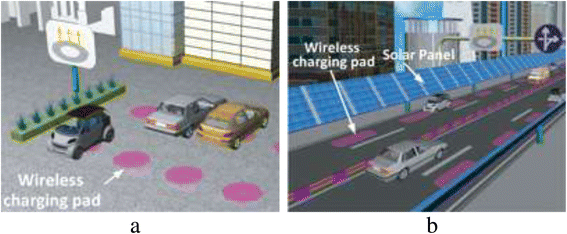
Typical structure of an integrated EV charger. Electric vehicle wireless charging systems. a Stationary charging; b dynamic charging

The magnetic resonance coupling occurs when two coils are specially designed with the same natural frequency, namely resonant inductive coupling [64]. The inductive coupling systems are also usually tuned to resonate, by using external capacitances rather than the inherent capacitance of a coil [65]. Most of commercialized wireless power transfer (WPT) systems use near-field and operate in the kilohertz band enabling large power transfer with 10 cm air gap between the emitting coil and the receiving coil, achieving an overall system efficiency in the low 90s [66]. The power transfer distance has been improved to 20 cm with the optimization of the magnetic structure [67]. On the other hand, the kilohertz operating frequency requires a large size coil and heavy ferrite materials, which reduce the vehicle payload efficiency and increase cost [66]. Higher frequency is generally desirable for building smaller and lighter WPT systems. However, there are restrictions on the performances of power switching devices and the usable frequency range under the regulation of industrial, scientific, and medical (ISM) band, etc. [68]. Current studies mainly deal with low-power WPT systems working at megahertz [69, 70]. For the WPT technology, other challenges such as EMI/EMC and EMF exposure for high-power applications, regulations, and standards, are also in a strong research and development phase [62]. Once more the control of the coil alignment, the maximization of the coupling and the negotiation between charger and vehicle must be provided by embedded systems, the complexity of which increases with the functions required. In this case, the charger/vehicle communication also must be wireless, as no physical connection is provided between them.
2.3.3 Impact of EV charging on the grid
The grid is severely challenged when a large number of EVs requires a large electric power and increases the peak demand [71]. When the level 1 uncoordinated charging strategy is applied, charging immediately starts after plug-in and finishes when the vehicle is fully charged or disconnected. This open loop scenario can lead to overload and thus to saturate the distribution transformers and feeders [72], causing a significant drop in their efficiency and life [73]. Another effect of many EVs simultaneously charged with no regulation is the drop of the grid voltage, that eventually leads to instability of the power system [74]. Introducing dual tariffs with cheap night rates can be a utility-provided incentive to the customer to reduce the peak load and delay the charging until the off-peak time.
Fast charging has undoubtedly the most significant impact on the grid. These chargers can easily lead to the distribution transformer overload and to the need for adjustments in the transformer capacity as well as the underground and over-head cables, which is an extremely expensive consequence. Moreover, a large market penetration of the EVs can also significantly degrade the life of the transformers. A viable solution in addition to the dual tariff introduction is to smartly coordinate the charging processes. The objectives of this optimization can be minimizing energy cost [71], maximizing battery life [75], minimizing transformer load surges [76], and maximizing customers’ satisfaction. The scenario is very demanding both from the optimization problem solution (e.g., various approaches including conventional centralized optimization techniques and decentralized techniques based on local information [77] have been proposed) and the requirements for the hardware platforms that must implement sophisticated negotiation algorithms based on the reliable knowledge of the neighbor behaviors.
A two-way energy flow and communication is adopted in vehicle to grid (V2G) technology. The EV fleet is aggregated to the grid to increase the efficiency and reliability of coordinated smart charging. This aggregation not only increases the efficiency of the conventional generation usage by enabling load shaping, but also is able to enhance the adoption of renewable energy resources by synchronizing electrical loads with strong wind and solar energy periods [78]. According to studies [79], EVs are able to provide the majority of demand for integration of wind energy into the power system. Some other studies propose charging schemes based on exclusive use of renewable energies to charge the plug-in fleet [80]. However, realization of the V2G technology requires enabling technologies such as two-way energy flow and communication, pricing policies, battery technology, embedded system integration, etc. Table 4 summarizes the impact of adopting EVs on the grid under different charging strategies.
3 Conclusions
An overview on the electrical transportation and the role of embedded systems is presented in this paper. Challenges and opportunities of transferring electrical energy from the grid to the electric vehicles are discussed. Advances in battery manufacturing imply that Li-ion batteries, thanks to their high-power and energy densities and long cycling lives, are the promising solution for the main energy storage system in EVs. Ultra-capacitor with high-power density can be combined with the battery to increase the efficiency of the energy storage system.
BMS is another important component of EVs to increase the efficiency and safety of the battery. Seven important features of the BMS fall into two major categories of hardware and software. The hardware part with cell monitoring, charge control, thermal management, and cell balancing provides safety and efficiency to the battery pack. The software part with algorithms to estimate the SOC and SOH provides accurate information about the internal state of the battery to the hardware parts, driver, and energy management units. However, developing methods for accurate estimation of SOC and SOH under different conditions is an ongoing research. Moreover, there are intensive investigations on developing active techniques to balance the cells in the battery pack.
The realization of E-transportation heavily relies on the availability of the charging infrastructure. EV charging technology is rapidly evolving to provide residential, commercial, and public charging stations with different charging specifications. Wireless technology is an upcoming feature to facilitate safe non-contacting stationary and dynamic charging of the vehicles. Another important aspect of E-transportation is the impact of a large penetration of EVs on the power grid. In spite of posing challenges such as inefficient power distribution and voltage deviation caused by this large penetration, the electric vehicle fleet can be seen as distributed energy storage for ancillary services and adoption of intermittent renewable energies. Enabling V2G plays a key role in realization of these services.
The backbone that is found in every aspect investigated in this paper is the presence of hardware platforms with which every control operation is carried out. Typically, the hardware is a system embedded in the vehicle components, provided with the proper interfaces to address the communication, control, and sensing needs. The embedded system controls the power electronic devices, negotiates with the partners in multi-agent scenarios, performs task fundamental such as power flow control and battery control and safety, so that we can conclude that vehicle electrification cannot be fully exploited without the contribution of the research on embedded systems.
References
W Su, H Rahimi Eichi, W Zeng, M-Y Chow, A survey on the electrification of transportation in a smart grid environment. IEEE Trans. Ind. Inf. 8, 1–10 (2012)
“Fuel Economy Guide”, available at https://www.fueleconomy.gov/feg/pdfs/guides/FEG2016.pdf, 16 Feb 2016
J Shen, S Dusmez, A Khaligh, Optimization of sizing and battery cycle life in battery/ultracapacitor hybrid energy storage systems for electric vehicle applications. IEEE Trans. Ind. Inf. 10(4), 2112–2121 (2014)
A Khaligh, Z Li, “Battery, ultracapacitor, fuel cell, and hybrid energy storage systems for electric, hybrid electric, fuel cell, and plug-in hybrid electric vehicles: state of the art”. IEEE Trans. Veh. Technol. 59, 2806–2814 (2010)
M Zandi, A Payman, JP Martin, S Pierfederici, B Davat, F Meibody-Tabar, Energy management of a fuel cell/supercapacitor/battery power source for electric vehicular applications. IEEE Trans. Veh. Technol. 60, 433–443 (2011)
L Lu, X Han, J Li, J Hua, M Ouyang, A review on the key issues for lithium-ion battery management in electric vehicles. J. Power Sources 226, 272–288 (2013)
SS Williamson, AK Rathore, F Musavi, Industrial electronics for electric transportation: current state-of-the-art and future challenges. IEEE Trans. Ind. Electron. 62(5), 3021–3032 (2015)
Agbinya J. Wireless Power Transfer. 2nd ed. (The River Publishers Series in Communications, 2015).
S Habib, M Kamran, U Rashid, Impact analysis of vehicle-to-grid technology and charging strategies of electric vehicles on distribution networks – a review. J. Power Sources 277, 205–214 (2015)
MS Whittingham, History, evolution, and future status of energy storage. Proc. IEEE 100, 1518–1534 (2012)
D Rotenberg, A Vahidi, I Kolmanovsky, Ultracapacitor assisted powertrains: modeling, control, sizing, and the impact on fuel economy. IEEE Trans. Control Syst. Technol. 19, 576–589 (2011)
A Kuperman, I Aharon, Battery–ultracapacitor hybrids for pulsed current loads: a review. Renew. Sust. Energ. Rev. 15, 981–992 (2011)
D Cericola, PW Ruch, R Kötz, P Novák, A Wokaun, Simulation of a supercapacitor/Li-ion battery hybrid for pulsed applications. J. Power Sources 195, 2731–2736 (2010)
J Moreno, ME Ortuzar, LW Dixon, Energy-management system for a hybrid electric vehicle, using ultracapacitors and neural networks. IEEE Trans. Ind. Electron. 53, 614–623 (2006)
Zhang X, Mi CC, Masrur A, Daniszewski D. Wavelet-transform-based power management of hybrid vehicles with multiple on-board energy sources including fuel cell, battery and ultracapacitor. J Power Sources. 2008;185:1533-43.
O Laldin, M Moshirvaziri, O Trescases, Predictive algorithm for optimizing power flow in hybrid ultracapacitor/battery storage systems for light electric vehicles. IEEE Trans. Power Electron. 28, 3882–3895 (2013)
G Ren, G Ma, N Cong, Review of electrical energy storage system for vehicular applications. Renew. Sustain. Energy Rev. 41, 225–236 (2015)
MT Lawder, B Suthar, PWC Northrop, S De, CM Hoff, O Leitermann, ML Crow, S Santhanagopalan, VR Subramanian, Battery energy storage system (BESS) and battery management system (BMS) for grid-scale applications. Proc. IEEE 102(6), 1014–1030 (2014)
H Rahimi-Eichi, U Ojha, F Baronti, M Chow, Battery management system: an overview of its application in the smart grid and electric vehicles. IEEE Ind. Electron. Mag. 7, 4–16 (2013)
D Andrea, Battery Management Systems for Large Lithium-Ion Battery Packs (Artech House, London, 2010)
C Alaoui, Solid-state thermal management for lithium-ion EV batteries. IEEE Trans. Veh. Technol. 62, 98–107 (2013)
KWE Cheng, BP Divakar, H Wu, K Ding, HF Ho, Battery-management system (BMS) and SOC development for electrical vehicles. IEEE Trans. Veh. Technol. 60, 76–88 (2011)
F Baronti, G Fantechi, R Roncella, R Saletti, P Terreni, Hardware Building Blocks of a Hierarchical Battery Management System for a Fuel Cell Hev, in IECON 2012 - 38th Annual Conference on IEEE Industrial Electronics Society, 2012, pp. 4041–4047
VRH Lorentz, MM Wenger, JL Grosch, M Giegerich, MPM Jank, M Marz et al., Novel Cost-Efficient Contactless Distributed Monitoring Concept for Smart Battery Cells, in 2012 IEEE International Symposium on Industrial Electronics (ISIE), 2012, pp. 1342–1347
F Baronti, G Fantechi, R Roncella, R Saletti, Intelligent Cell Gauge for a Hierarchical Battery Management System, in 2012 IEEE Transportation Electrification Conference and Expo (ITEC), 2012, pp. 1–5
M Schneider, S Ilgin, N Jegenhorst, R Kube, S Puttjer, K Riemschneider et al., Automotive Battery Monitoring by Wireless Cell Sensors, in 2012 IEEE International Instrumentation and Measurement Technology Conference (I2MTC), 2012, pp. 816–820
K Hahnsang, KG Shin, DESA: dependable, efficient, scalable architecture for management of large-scale batteries. IEEE Trans. Ind. Inf. 8, 406–417 (2012)
TA Stuart, W Zhu, Modularized battery management for large lithium ion cells. J. Power Sources 196, 458–464 (2011)
T Kim, W Qiao, Q Liyan, Power electronics-enabled self-X multicell batteries: a design toward smart batteries. IEEE Trans. Power Electron. 27, 4723–4733 (2012)
A Manenti, A Abba, A Merati, SM Savaresi, A Geraci, A new BMS architecture based on cell redundancy. IEEE Trans. Ind. Electron. 58, 4314–4322 (2011)
F Baronti, G Fantechi, R Roncella, R Saletti, Design of a Module Switch for Battery Pack Reconfiguration in High-Power Applications, in 2012 IEEE International Symposium on Industrial Electronics (ISIE), 2012, pp. 1330–1335
KS Ng, C-S Moo, Y-P Chen, Y-C Hsieh, Enhanced coulomb counting method for estimating state-of-charge and state-of-health of lithium-ion batteries. Appl. Energy 86, 1506–1511 (2009)
M Coleman, CK Lee, C Zhu, WG Hurley, State-of-charge determination from EMF voltage estimation: Using impedance, terminal voltage, and current for lead-acid and lithium-ion batteries. IEEE Trans. Ind. Electron. 54, 2550–2557 (2007)
R Li, J Wu, H Wang, G Li, Prediction of State of Charge of Lithium-ion Rechargeable Battery with Electrochemical Impedance Spectroscopy Theory, in 5th IEEE Conference on Industrial Electronics and Applications, ICIEA 2010, June 15, 2010 - June 17, 2010, Taichung, Taiwan, 2010, pp. 684–688
GL Plett, Extended Kalman filtering for battery management systems of LiPB-based HEV battery packs - Part 2. Modeling and identification. J. Power Sources 134, 262–276 (2004)
M Shahriari, M Farrokhi, Online state-of-health estimation of VRLA batteries using state of charge. IEEE Trans. Ind. Electron. 60, 191–202 (2013)
M Charkhgard, M Farrokhi, State-of-charge estimation for lithium-ion batteries using neural networks and EKF. IEEE Trans. Ind. Electron. 57, 4178–4187 (2010)
I-S Kim, A technique for estimating the state of health of lithium batteries through a dual-sliding-mode observer. IEEE Trans. Power Electron. 25, 1013–1022 (2010)
H Rahimi-Eichi, F Baronti, M Chow, Online adaptive parameters identification and state of charge co-estimation for lithium-polymer battery cells. IEEE Trans. Ind. Electron. 61(4), 2053–2061 (2014)
M Ecker, JB Gerschler, J Vogel, S Käbitz, F Hust, P Dechent et al., Development of a lifetime prediction model for lithium-ion batteries based on extended accelerated aging test data. J. Power Sources 215, 248–257 (2012)
H Dai, X Wei, Z Sun, A new SOH Prediction Concept for the Power Lithium-ion Battery Used on HEVs, in 2009 IEEE Vehicle Power and Propulsion Conference, 2009, pp. 1649–1653
J Kim, BH Cho, State-of-charge estimation and state-of-health prediction of a Li-Ion degraded battery based on an EKF combined with a per-unit system. IEEE Trans. Veh. Technol. 60, 4249–4260 (2011)
GL Plett, Recursive approximate weighted total least squares estimation of battery cell total capacity. J. Power Sources 196, 2319–2331 (2011)
D Andre, A Nuhic, T Soczka-Guth, DU Sauer, Comparative study of a structured neural network and an extended Kalman filter for state of health determination of lithium-ion batteries in hybrid electric vehicles. Eng. Appl. Artif. Intell. 26, 951–961 (2013)
H Rahimi-Eichi, M-Y Chow, Adaptive Online Battery Parameters/SOC/Capacity Co-Estimation, in 2013 IEEE Transportation Electrification Conference and Expo (ITEC), 2013, pp. 1–6
B Saha, E Koshimoto, CC Quach, EF Hogge, TH Strom, BL Hill et al., Battery Health Management System for Electric UAVs, in 2011 IEEE Aerospace Conference, 2011, pp. 1–9
SM Rezvanizaniani, Z Liu, Y Chen, J Lee, Review and recent advances in battery health monitoring and prognostics technologies for electric vehicle (EV) safety and mobility. J. Power Sources 256, 110–124 (2014)
J Cao, N Schofield, A Emadi, Battery Balancing Methods: a Comprehensive Review, in 2008 IEEE Vehicle Power and Propulsion Conference, VPPC '08, 2008, pp. 1–6
WC Lee, D Drury, P Mellor, Comparison of Passive Cell Balancing and Active Cell Balancing for Automotive Batteries, in 2011 IEEE Vehicle Power and Propulsion Conference (VPPC), 2011, pp. 1–7
J Gallardo-Lozano, E Romero-Cadaval, MI Milanes-Montero, MA Guerrero-Martinez, Battery equalization active methods. J. Power Sources 246, 934–949 (2014)
S-H Park, K-B Park, H-S Kim, G-W Moon, M-J Youn, Single-magnetic cell-to-cell charge equalization converter with reduced number of transformer windings. IEEE Trans. Power Electron. 27, 2900–2911 (2012)
M Einhorn, W Guertlschmid, T Blochberger, R Kumpusch, R Permann, FV Conte et al., A current equalization method for serially connected battery cells using a single power converter for each cell. IEEE Trans. Veh. Technol. 60, 4227–4237 (2011)
M Einhorn, W Roessler, J Fleig, Improved performance of serially connected Li-Ion batteries with active cell balancing in electric vehicles. IEEE Trans. Veh. Technol. 60, 2448–2457 (2011)
PA Cassani, SS Williamson, Design, testing, and validation of a simplified control scheme for a novel plug-in hybrid electric vehicle battery cell equalizer. IEEE Trans. Ind. Electron. 57, 3956–3962 (2010)
M Uno, K Tanaka, Single-switch multioutput charger using voltage multiplier for series-connected lithium-Ion battery/supercapacitor equalization. IEEE Trans. Ind. Electron. 60, 3227–3239 (2013)
F Baronti, G Fantechi, R Roncella, R Saletti, High-efficiency digitally controlled charge equalizer for series-connected cells based on switching converter and super-capacitor. IEEE Trans. Ind. Inf. 9, 1139–1147 (2013)
F Baronti, R Roncella, R Saletti, Performance comparison of active balancing techniques for lithium-ion batteries. J. Power Sources 267, 603–609 (2014)
SAE International, SAE Electric Vehicle and Plug in Hybrid Electric Vehicle Conductive Coupler (SAE J1772) (SAE International, Troy, 2010)
SAE International (2012). J1772 ‘combo connector’ shown at the 2012 Electric Vehicle Symposium [Online]. Available: http://articles.sae.org/11005/.
International Electrotechnical Commission (2014). New IEC Standards bring mass EV adoption a step closer [Online]. Available: http://www.iec.ch/newslog/2014/nr1014.htm
J Fishelson, K Heaslip, W Louisell, K Womack, An Evaluation Framework for an Automated Electric Transportation Network, in The 90th Transportation Research Board Annual Meeting, Washington, DC, January 2011, 2011
H Rakouth, J Absmeier, A Brown Jr, I-S Suh, MM John, R Sumner et al., EV Charging Through Wireless Power Transfer: Analysis of Efficiency Optimization and Technology Trends, in The FISITA 2012 World Automotive Congress Beijing, China, 2013, pp. 871–884
N Shinohara, Power without wires. IEEE Microw. Mag. 12, S64–S73 (2011)
A Kurs, A Karalis, R Moffatt, JD Joannopoulos, P Fisher, M Soljačić, Wireless power transfer via strongly coupled magnetic resonances. Science 317, 83–86 (2007)
AP Hu, Wireless/Contactless Power Supply: Inductively coupled resonant converter solutions (VDM Verlag, Saarbrücken, 2009)
K Kobayashi, T Pontefract, Y Kamiya, Y Daisho, Development and Performance Evaluation of a Non-Contact Rapid Charging Inductive Power Supply System for Electric Micro-bus, in 2011 IEEE Vehicle Power and Propulsion Conference (VPPC), 2011, pp. 1–6
M Budhia, GA Covic, JT Boys, Design and optimization of circular magnetic structures for lumped inductive power transfer systems. IEEE Trans. Power Electron. 26, 3096–3108 (2011)
R. A. Group, Improving the Effectiveness, Flexibility and Availability of Spectrum for Short Range Devices, in presented at the International Telecommunication Union, Geneva, Switzerland, Jan 2007, 2007
S-H Lee, RD Lorenz, Development and validation of model for 95 %-efficiency 220-W wireless power transfer over a 30-cm air gap. IEEE Trans. Ind. Appl. 47, 2495–2504 (2011)
T Imura, Y Hori, Maximizing air gap and efficiency of magnetic resonant coupling for wireless power transfer using equivalent circuit and Neumann formula. IEEE Trans. Ind. Electron. 58, 4746–4752 (2011)
J Wang, C Liu, D Ton, Y Zhou, J Kim, A Vyas, Impact of plug-in hybrid electric vehicles on power systems with demand response and wind power. Energy Policy 39, 4016–4021 (2011)
S Shao, M Pipattanasomporn, S Rahman, Challenges of PHEV Penetration to the Residential Distribution Network, in 2009 IEEE Power & Energy Society General Meeting, PES’09, 2009, pp. 1–8
AD Hilshey, PDH Hines, P Rezaei, JR Dowds, Estimating the impact of electric vehicle smart charging on distribution transformer aging. IEEE Trans. Smart Grid 4, 905–913 (2013)
K Clement-Nyns, E Haesen, J Driesen, The impact of charging plug-in hybrid electric vehicles on a residential distribution grid. IEEE Trans. Power Syst. 25, 371–380 (2010)
S Bashash, SJ Moura, JC Forman, HK Fathy, Plug-in hybrid electric vehicle charge pattern optimization for energy cost and battery longevity. J. Power Sources 196, 541–549 (2011)
P Fairley, Speed bumps ahead for electric-vehicle charging. IEEE Spectr. 47, 13–14 (2010)
Z Fan, A distributed demand response algorithm and its application to PHEV charging in smart grids. IEEE Trans. Smart Grid 3, 1280–1290 (2012)
N De Forest, J Funk, A Lorimer, B Ur, I Sidhu, P Kaminsky et al., Impact of Widespread Electric Vehicle Adoption on the Electrical Utility Business-Threats and Opportunities (Center for Entrepreneurship & Technology (CET), Berkeley, 2009)
W Hu, C Su, Z Chen, B Bak-Jensen, Optimal operation of plug-in electric vehicles in power systems with high wind power penetrations. IEEE Trans. Sustainable Energy 4, 577–585 (2013)
T Markel, M Kuss, P Denholm, Communication and Control of Electric Drive Vehicles Supporting Renewables, in 2009 IEEE Vehicle Power and Propulsion Conference, VPPC ‘09, 2009, pp. 27–34
Acknowledgements
This work was partly funded by the ECSEL Joint Undertaking under grant agreement No. 662192 (3Ccar).
Author information
Authors and Affiliations
Corresponding author
Additional information
Competing interests
The authors declare that they have no competing interests.
Rights and permissions
Open Access This article is distributed under the terms of the Creative Commons Attribution 4.0 International License (http://creativecommons.org/licenses/by/4.0/), which permits unrestricted use, distribution, and reproduction in any medium, provided you give appropriate credit to the original author(s) and the source, provide a link to the Creative Commons license, and indicate if changes were made.
About this article

Cite this article
Baronti, F., Chow, MY., Ma, C. et al. E-transportation: the role of embedded systems in electric energy transfer from grid to vehicle. J Embedded Systems 2016, 11 (2016). https://doi.org/10.1186/s13639-016-0032-z
Received:
Accepted:
Published:
DOI: https://doi.org/10.1186/s13639-016-0032-z