
Abstract
We present a novel robust and secure steganography technique to hide images into audio files aiming at increasing the carrier medium capacity. The audio files are in the standard WAV format, which is based on the LSB algorithm, while images are compressed by the GMPR technique which is based on the Discrete Cosine Transform and high-frequency minimization encoding algorithm. The method involves compression–encryption of an image file by the GMPR technique followed by hiding it into audio data by appropriate bit substitution. The maximum number of bits without significant effect on audio signal for LSB audio steganography is 6 LSBs. The encrypted image bits are hidden into variable and multiple LSB layers in the proposed method. Experimental results from observed listening tests show that there is no significant difference between the stego-audio reconstructed from the novel technique and the original signal. A performance evaluation has been carried out according to quality measurement criteria of signal-to-noise ratio and peak signal-to-noise ratio.
Introduction
Steganography is the skilful masking of data in a coating media such as text, image and video. The term steganography originates from Greek which means “Covered Writing”. Steganography is a widely used technique in the area of information technology [1]. Throughout history, steganography methods included methods such as hiding messages in the belly of a hare using invisible ink or shaving of a courier’s head to write a message or a tattoo, or an image on the messenger’s head [2]. Steganography thus supplies techniques to cover the existence of a secondary message inside a primitive message. The primitive message is delegate to as the carrier signal which could be text, audio, image, video, etc., while the secondary (hidden) message is assigned to as the loaded message [3]. A signal is being hidden in such a way to be unrecognized to the onlooker, while the primary signal (carrier) is modified in an imperceptible form [4]. Therefore, in steganography the original message is not changed and the presence of a hidden message is not apparent to the observer as it is embedded in the selected medium [5].
Audio steganography is defined as the Cover Audio + Secret data = Stego-audio signal [6,7,8]. The essential requirements for audio steganography are: (1) the secret data should not be perceptible to humans [6, 7]; (2) it should maximize the hiding capacity; and (3) preferably, the hidden data should be encrypted. In the digital world, two types of objects are used: either audio or image files as stego-objects for masking the furtive message [9]. By performing a bit change in the binary sequence of a sound file, the secret data are embedded into the original file. In the last few years, different approaches have been developed for the hiding and extraction of a data from audio signals. Most of the developed approaches are based on the cognitive characteristics of the human auditory system (HAS) in order to add a message/data to a host signal in a cognitive transparent way. Hiding data/message into audio signals is an interesting endeavour, but at the same time more difficult than hiding into images, as the HAS is more sensitive to small variations in sound than the human visual system (HVS) is to small changes in image intensities [10].
The objective is thus, to merge the secret data into an audio data such that there are insignificant differences between the original audio data and the embedded file. The embedded file contains a header, with essential information about the audio. This information is untouchable; in a WAVE file for instance, the first 44 bytes contain information about the file and any changes to this header will corrupt the WAVE file [3]. A general audio steganography method is illustrated in Fig. 1.

General audio steganography method
The masking of the confidential data into the secret medium should not make any loathsome changes to the secret medium so that the authenticity of the file should not be disturbed [11]. The audio steganography view is to merge precious/undercover encrypted data into an audio data in such a way that the human auditory system (HAS) cannot expose the changes which happened through merger of the encrypted data into the audio data. In audio steganography, the least significant bit (LSB), spread spectrum and echo hiding approaches have been developed in recent years [12]. The main properties of audio steganography [2] being exploited in different steganography applications are: confidentiality, imperceptibility, high capacity, difficult to detect ability, accuracy, survivability and visibility.
State-of-the-Art in Audio Steganography
In [13], an approach is described for resolving the problem related to the substitution technique of audio steganography. In the first level of security, the RSA algorithm is used to encrypt the message and, in the next level, the encrypted message is encoded into audio data. A genetic algorithm-based substitution method is used to encode the data. The basic idea behind the method is to enhance both security and robustness of audio steganography. In [14], a novel approach is proposed where a dual encryption methodology is implemented. In the first level of encryption, a pattern matching algorithm has been employed to encrypt the text message in terms of their positional value. In the second level, the conventional LSB method has been used to embed the positional value in the cover file. Such a dual encryption method ensures data security in an efficient manner. In [15], a method for concealing data is proposed through an amalgamation of text encryption, audio steganography and audio encryption. In the first step, the original text message is encrypted using a modified Vigenère cipher algorithm. The cipher text gets embedded into the cover audio using LSB encoding in the second step. Finally, the audio file is then subjected to transposition making use of Blum Blum Shub pseudorandom number generator. The authors recommend more secure encryption algorithms to be utilized for text encryption, so that data are not easily decoded by an unauthorized party. The work in [16] gives an overview of two primitive techniques to highlight how steganography in audio file works and what are their main desirable characteristics. Both LSB modification and phase encoding techniques are extensively exploited. The main characteristics of an effective audio steganographic scheme are emphasized as inaudibility of distortion, data rate and robustness. These characteristics are referred to as the magic triangle of data hiding.
The novel contributions of this paper are best described in the context of our previous work on image compression [17]. In that work, we used double discrete transforms (i.e. DCT—Discrete Cosine Transform and DWT—Discrete Wavelet Transform) combined with matrix minimization algorithm yielding 94% compression ratios for grey scale conventional images. The main disadvantage of the previous method was excessive compression and decompression execution times that could run from seconds to minutes. The proposed method described here is based on an enhanced matrix minimization algorithm (see “The GMPR Compression–Encryption Algorithm” section). The method is based on the DCT and is time-wise more efficient than previous methods. A further contribution of the proposed method is higher compression ratios compared with both previous work [17] and the JPEG technique. In this paper, the proposed method (based on DCT with enhanced matrix minimization algorithm) is compared with the DCT-based JPEG technique, as this is the closest technique to the proposed method.
Method
The proposed algorithm aims at reducing noise, increasing robustness and increasing compressed–encrypted image embedding capacity by including negative audio bytes in the encoding process. In this paper, the compressed–encrypted image can be hidden into the audio file using the following two major steps:
- 1.
- 2.
Hide the image into audio files using LSB-based encoding.
In the first step, the secret image file is encrypted and compressed using the GMPR algorithm (see “The GMPR Compression–Encryption Algorithm” section for more details). The sender generates a compression–encryption key. This key is transferred to the receiver through secure means. The encrypted image is converted into a binary string array list.
In the second step, the encrypted image is converted into a stream of bits to encode using the proposed LSB Algorithm. The proposed steganography algorithm embeds the 6-bits (encrypted image) randomly into the audio byte in the higher LSB positions (1–10) for audio byte (the audio byte can be processed as 16-bit sample). This operation is done 100 times every sample by calculating the difference between the value of original audio sample and the value of the 100 stego-audio samples. The best embedding position is the sample that has the least difference between it and the original sample.
The following steps provide a detailed explanation on how to encode the message data into the given audio file:
Read the image file and compress–encrypt it using the GMPR method which will generate the key for decompression. The key is transferred to the receiver through secure means (not part of the algorithm).
The encrypted image file is converted into a binary string array list.
Read the cover audio file and convert to binary (16-bits).
To embed the encrypted image bits, instead of using the least significant bits, higher (LSB) is used. In order to increase the quality of audio, the secret data bits are randomly embedded into audio samples. In each sample, 6 bits are embedded randomly in (1–10) positions. To find the best embedding position, the following steps are performed:
- 1.
Substitute audio bits with encrypted image bits.
- 2.
For every sample, repeat this substitution randomly 100 times and evaluate the difference between the original audio sample and the generated (substituted) audio sample bytes.
- 3.
To reduce the amount of error, choose the sample with smaller difference. Eventually, the best embedding position is the minimum value of difference found in the sample. Record the sample positions.
- 4.
The next step after finding the best embedding position is to place the encrypted image bits sequentially inside the audio samples at the specified locations.
- 1.
Repeat steps 1–4 for all encrypted image bytes.
Mark the end of message encoding.
The last step is writing the audio bytes into the output audio file (stego-file). This is done sample by sample.
The workflow of embedding operation for the proposed algorithm is depicted in Fig. 2.

The workflow of embedding operation for the proposed method
The GMPR Compression–Encryption Algorithm
In this section, the image compression–encryption is described. The method has been developed by Siddeq and Rodrigues at Sheffield Hallam University [17, 18]. First, the image is compressed by a combination of either DWT—Discrete Wavelet Transform and DCT—Discrete Cosine Transform. In this paper, we use the DCT. Second, the matrix minimization algorithm produces a stream of encoded data. Third, header information with compression keys is concatenated to encoded data representing the compressed–encrypted image to be used in the steganography step.
The compression algorithm involves applying the DCT with quantization leading to two matrices: the DC-Array and the AC coefficients [4, 5]. Figure 3 shows a layout of the compression–encryption method. The portion of this paper related to the compression of the matrix of AC coefficients which involves reducing the number of zeros in the matrix by the matrix minimization approach yielding a minimized array. The DC-Array can be represented in a few bytes by computing the differential between two adjacent coefficients in the array, increasing thus, the compression ratio for the array [17]. Both encoded DC and AC coefficients are then subjected to arithmetic coding.

Illustration of the GMPR image compression–encryption algorithm
GMPR Compression Step 1: Discrete Cosine Transform (DCT)
Divide the image into blocks n × n, followed by DCT which is applied to each block independently. The output from DCT is a set of de-correlated coefficients, and it means that each block consists of a DC value (the first position in the block), while all other values are called the AC coefficients. The DCT is defined by Eq. (1) [19]:
where \(a\left( u \right) = \sqrt {\frac{1}{n}} , {\text{ for }} u = 0, a\left( u \right) = \sqrt {\frac{2}{n}} ,\;{\text{for}}\;u \ne 0\). where \(i,j = 1,2, \ldots ,n\).
The quantization of each block \(n \times n\) can be represented as follows:
The transformation is followed by quantization by rounding off floating-point values to integers. Each n × n block is quantized by Eq. (2) using dot-division-matrix. The main reason to use quantization is to remove insignificant coefficients (from AC coefficients) leading to an increased number of zeroes in each block, which then yields increased compression ratios.
The parameter L is used to change the quantization values in matrix Q. Therefore, image quality is decreased or increased according to the value of L. The range of L depends on the maximum value of the DCT coefficients. Thus, the minimum value is L = 1 and the maximum value is L = maximum value of DCT coefficients.
Next, the GMPR algorithm separates the DC components from each block by saving them into a new array called DC-Array. After that, the differential between two adjacent values in the DC-Array is computed. The reason behind this process is to increase compression ratios and facilitate lossless data compression (by arithmetic coding). For information, values in the DC-Array are generally similar. So, the differences between these values are small and many of these data may be repeated [18].
where i = 1, 2… p − 1 and p is the size of D.
The remaining AC coefficients (for example, for an 8 × 8 block there are 63 remaining AC coefficients) of each block are converted into an array and concatenated together. This means that we generate multiple arrays (each block is converted to an array by column-scan). The new array is called AC-Matrix. Now, this matrix is ready for coding by the matrix minimization algorithm which is described in the next section.
GMPR Compression Step 2: Matrix Minimization Algorithm
The output from GMPR Step 1 is an AC-Matrix and a DC-Array. Here, the AC-Matrix is encoded by the matrix minimization method, which focus on reduction in zeros and squeezing each triplet data into a value, and then the output is subjected to arithmetic coding. Normally, the AC-Matrix has a large number of zeros with some data scattered randomly in the matrix. A technique to eliminate blocks of zeros and save blocks of nonzero data into an array starts by dividing the AC-Matrix into non-overlapping blocks n × n (n ≥ 8). Each block has been checked for nonzero data, if nonzero data are found, then the block is saved as a nonzero array. Meanwhile, the location of that block is recorded which means that all missing blocks contain just zeros. The algorithm is illustrated below [17].

Once only nonzero data are saved into the R-Array, the matrix minimization algorithm is applied to encrypt and compress at 3:1 ratio (that is, every 3 values are coded into a single value). This process uses three key values and multiplies these keys by three adjacent entries in the R-Array which are then summed over and saved in an encoded array called E-Array. It is important to note that the compression keys K1, K2, K3 are data dependent and generated by a key generator algorithm as follows [18]:
Assuming that N is the length of R-Array, \(i = 1,2, \ldots ,N - 3\) is the index of data in R-Array, and j is the index of E-Array (encrypted array), the following transformation defines the high-frequency minimization encoding:
Each value of the encoded E-Array is from triplet summation of Eq. (9), and the reduced R-Array can later be reconstructed through search for values for that block. However, this problem requires extra information which is kept in the header of the compressed file as an array of unique data as shown in Fig. 4.

Each image has its own AC-Matrix coefficients. The GMPR algorithm computes the Unique-Data for the AC-Matrix so that this Unique-Data cannot be used to decode another image’s AC-Matrix. The final step of GMPR compression is to apply arithmetic coding to the E-Array yielding a stream of lossless data. Arithmetic coding computes the probability of all data and then set a range to each data (low and high) used by two special equations to produce a single floating-point value; this floating-point value is converted to a stream of bits and saved as compressed file. The main reason we use arithmetic coding instead of Huffman coding is because it yields higher compression ratios although the performance of Huffman coding is higher [18].
The GMPR Decompression–Decryption Steps
In the first step in the GMPR decompression–decryption method, the DC-Array can be decoded in a very simple way, by an addition process (i.e. the inverse of Eq. (3)) as described by Eq. (10) below.
where p represents the last location in the DC-Array. The addition process takes the last value at position p and adds it to the previous adjacent value, and then the total adds to the next previous adjacent value and so on. This process will continue until p = 1 (first position).
In the second step, we focus on recovering the R-Array that has been compressed into the E-Array. For this purpose, Siddeq and Rodrigues proposed a binary search algorithm (BS-Algorithm) [18]. The header compressed file contains information about the three keys (i.e. defined in Eqs. (6–8)—K1, K2 and K3), the unique data and compressed streams of data (E-Array), respectively. The BS-Algorithm role is to fetch each compressed value from the E-Array and reconstruct the original triplet R-Array of data. This is described in steps A–D [17, 18] below where Unique-Data array is sorted ascending:
- (A)
Estimate 3 coefficient values from the Unique-Data array as Unique-Data1 = Unique-Data2 = Unique-Data3. The search algorithm computes all possible outputs from Eq. (9), which based on K1, K2 and K3. Therefore, the output is saved in an temporary array called estimated E-Array. As a means of an example, consider that [Unique-Data1, Unique-Data2, Unique-Data3] = [A1, A2, A3] (that is, the first 3 values in the Unique-Data array). Then, according to Eq. (9) these represent the R-Array values summation, respectively, and the equation is executed multiple times, to build the R-Array, as described in Fig. 5a. A match indicates that the estimated Unique-Data1, Unique-Data2 and Unique-Data3 represent the recovered data.
Fig. 5 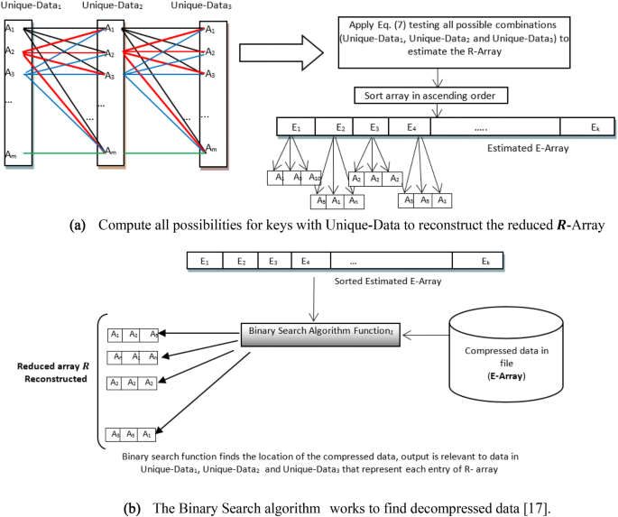
The BS-Algorithm to reconstruct the R-Array
- (B)
A binary search algorithm [20] is used to recover the data and their keys. Our design consists of single binary search algorithm to reconstruct the triplets of original data in the R-Array, as shown in Fig. 5b. At each step, the decompressed data are compared with the middle element of the estimated E-Array. If the values match, then a matching element has been found and its relevant (Unique-Data1, Unique-Data2 and Unique-Data3) returned. Otherwise, if the search is less than the middle element, the algorithm is repeated to the left of the middle element or, if the value is greater, to the right until a match is found.
- (C)
Once the R-Array is reconstructed, the nonzero blocks are relocated in an empty matrix according to locations saved by Algorithm 1 (“Introduction” section), these will be used to reconstruct the AC-Matrix.
- (D)
The DC-Array values are combined with the AC coefficients, and the high-frequency AC-Matrix is re-built. Each row from the AC-Matrix is converted to a block n × n, and then followed by inverse quantization (dot multiplication with Eq. (2)), and the inverse DCT is applied to each n × n block according to Eq. (11) defined below, to reconstruct the original image. Figure 6 illustrates the decompression–decryption steps [19].
$$f\left( {x,y} \right) = \mathop \sum \limits_{u = 0}^{{{\text{Block}} - 1}} \mathop \sum \limits_{v = 0}^{{{\text{Block}} - 1}} a\left( u \right)a\left( v \right)C\left( {u,v} \right)\cos \left[ {\frac{{\left( {2X + 1} \right)u\pi }}{{2{\text{Block}}}}} \right]\cos \left[ {\frac{{\left( {2y + 1} \right)v\pi }}{{2{\text{Block}}}}} \right]$$(11)Fig. 6 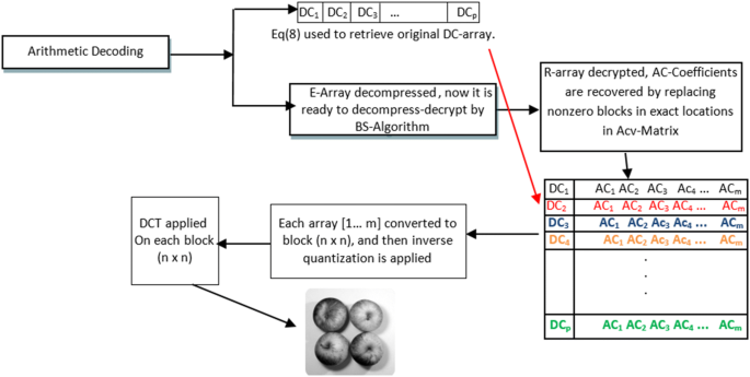
The layout of the GMPR decompression–decryption


Results and Analysis
The proposed method is demonstrated by (1) comparing the signal-to-noise ratio (SNR) and peak signal-to-noise ratio (PSNR) values obtained from 8 × 8 and 16 × 16 block sizes; (2) plotting the resulting stego-audio file and comparing it with original audio file; and (3) listening to the original and stego-files for perceptual assessment. To test the performance of the proposed method, the used audio files frequency is 44.1 kHz and its duration is 7 s. Different image file sizes are used (as shown in Table 1). First, the SNR and PSNR are computed for the original audio file and stego-audio files using proposed method. Table 1 shows results of SNR and PSNR for the original and stego-audio files after embedding the secret image divided into blocks of 8 × 8 and 16 × 16.
As shown in Table 1, block sizes of 8 × 8 (light grey) yield larger image sizes than block sizes of 16 × 16 (dark grey). The result is that we can embed only two images of 8 × 8 block size into the audio file, while we can embed four 16 × 16 block images into the same audio file. The perceptual assessment of the stego-audio file of the proposed work is almost the same when compared with the original audio file, it is hard to notice any difference. As presented in Table 1, the SNR and PSNR values of proposed work are high. High values mean that the hidden message remains undetected or it is hard to notice. By using 6 LSB, the information embedding capacity is high.
Figure 7 depicts the difference between the original audio file and the stego-audio file using the proposed method. The stego-audio file after embedding 2 images with 8 × 8 block compression is shown in Fig. 7a, and the stego-audio file after embedding 4 images with 16x16 block compression is shown in Fig. 7b. Both are almost identical as compared with the original audio file.

Deviation between the original and stego-audio files
Figure 8 shows that before and after embedding, the overall size of the audio file remains the same. Thus, the audio steganography is successful as there are undetectable or non-audible differences between the original and the stego-files. The original cover audio sample is shown in Fig. 8a, the stego wav file after embedding 2 images (8 × 8) is shown in Fig. 8b, and the stego wav file after embedding 4 images (16 × 16) is shown in Fig. 8c.

The waveform of original and stego-audio files using the proposed methods
Comparison with JPEG
JPEG is a main technique used in many digital image processing applications and digital video processing, for this reason we chose this technique to compare with our approach [19]. Another reason is that JPEG is based on the DCT, and, by necessity, there are a few steps in the JPEG technique that are similar to our compression–encryption method [17]. The assessment presented here focuses on image quality (root mean square error—RMSE) [17, 18] and compression ratios, before engaging with the steganography method. Table 2 shows our compression–encryption method results, while Table 3 shows the comparison between our method and JPEG technique. Figures 9 and 10 show the decompressed images by our method and JPEG technique, respectively.

(Left): Original 2D images with different dimensions. (Middle and right), decompressed 2D images by the GMPR compression–encryption method representing high- and low-resolution images, respectively

Decompressed 2D images by JPEG technique at higher compression ratios
Conclusions
A new method for embedding image data into audio files using random and higher LSB audio steganography has been successfully demonstrated in this paper. The proposed technique offers large capacity for secret message embedding, it is robust, and the quality of embedded images is not reduced by noise or other artefact distortions. The proposed technique is robust to stego-analysis attacks because in the cover audio file more than one bit has been changed to produce the stego-file. The resulting stego-audio file has high PSNR and SNR ratios indicating small noise distortions. Perceptually, the resulting stego-audio file is almost identical to the cover audio file, so the embedding is imperceptible.
The analysis of the proposed algorithms indicates that the most important aspects of the method and their role in providing robust embedding and recovering of high-quality image with high compression ratios are as follows:
- 1.
As a first step, DCT was applied to block sizes 8x8 and 16x16, after that the DC components and AC coefficients are split into two different matrices, and each of these matrices is coded separately.
- 2.
Normally, the AC coefficients contain a large number of zeros. The elimination of zero data and the keeping of significant information by the matrix minimization algorithm reduces the AC-Matrix contents by more than 80%.
- 3.
The matrix minimization algorithm replaces each three coefficients from the AC coefficients by a single floating-point value leading to increased compression ratios.
- 4.
At decompression stage, the BS-Algorithm is the engine for estimating the original data from the E-Array and relies on the key values and the availability of a set of unique data.
- 5.
The keys used in the compression–encryption method are data-dependent, and, without the keys, images cannot be decoded. For this reason, the method is referred to as image compression–encryption and suitable for secure transmission and storage of data.
- 6.
The compression–encryption image algorithm was tested on grey images at high compression ratios and compared with the JPEG technique. Results demonstrate that our method is more suitable than JPEG for steganography yielding higher compression ratios as shown in Table 3.
Finally, Table 1 has shown that the proposed technique yields SNR over 61% which is higher than work reported in the literature. In addition, the proposed method offers a level of security that is unmatched by current work. We understand that developing steganography methods that are at the same time highly secure and highly robust are difficult to achieve. We demonstrated methods that make a significant contribution towards such requirements so that future work will be focused on improving on those requirements.
References
Bangera KN, Reddy NS, Paddambail Y, Shivaprasad G. Multilayer security using RSA cryptography and dual audio steganography. In: 2017 2nd IEEE international conference on recent trends in electronics, information & communication technology (RTEICT). IEEE; 2017, p. 492–5.
El-Khamy SE, Korany NO, El-Sherif MH. A security enhanced robust audio steganography algorithm for image hiding using sample comparison in discrete wavelet transform domain and RSA encryption. Multimed Tools Appl. 2017;76(22):24091–106.
Prasad LC, Rao VSR. MATLAB implementation of audio steganography for secure data transmission; 2017.
Hashim J, Hameed A, Abbas MJ, Awais M, Qazi HA, Abbas S. LSB Modification based audio steganography using advanced encryption standard (AES-256) technique. In: 2018 12th international conference on mathematics, actuarial science, computer science and statistics (MACS). IEEE; 2018, p. 1–6.
Kundu N, Kaur A. Audio steganography for secure data transmission. Int J Comput Sci Eng. 2017;5(2):124–9.
Atoum MS, Alnabhan MM, Habboush A. Advanced LSB technique for audio stenography. CoSIT, SIGL, AIAPP, CYBI, CRIS, SEC, DMA; 2017, p. 79–86.
Din R, Mahmuddin M, Qasim AJ. Review on steganography methods in multi-media domain. Int J Eng Technol. 2019;8(1.7):288–92.
Chen K, Yan F, Iliyasu AM, Zhao J. Exploring the implementation of steganography protocols on quantum audio signals. Int J Theor Phys. 2018;57(2):476–94.
Ali AH, George LE, Zaidan AA, Mokhtar MR. High capacity, transparent and secure audio steganography model based on fractal coding and chaotic map in temporal domain. Multimed Tools Appl. 2018;77(23):31487–516.
Mohamad FS, Yasin NSM. Information hiding based on audio steganography using least significant bit. Int J Eng Technol. 2018;7(4.15):536–8.
Mohajon J, Ahammed Z, Talukder KH. An improved approach in audio steganography using genetic algorithm with K-bit symmetric security key. In: 2018 21st international conference of computer and information technology (ICCIT). IEEE; 2018, p. 1–6.
Tan D, Lu Y, Yan X, Wang X. A simple review of audio steganography. In: 2019 IEEE 3rd information technology, networking, electronic and automation control conference (ITNEC). IEEE; 2019, p. 1409–13.
Singh G, Tiwari K, Singh S. Audio steganography using RSA algorithm and genetic based substitution method to enhance security. Int J Sci Eng Res. 2014;5(5):703–7.
Chowdhury R, Bhattacharyya D, Bandyopadhyay SK, Kim TH. A view on LSB based audio steganography. Int J Secur Appl. 2016;10(2):51–62.
Sinha N, Bhowmick A, Kishore B. Encrypted information hiding using audio steganography and audio cryptography. Int J Comput Appl. 2015;112(5):49–53.
Bandyopadhyay SK, Banik BG. Multi-level steganographic algorithm for audio steganography using LSB modification and parity encoding technique. Int J Emerg Trends Technol Comput Sci. 2012;1(1):71–4.
Siddeq M, Rodrigues M. A novel 2D image compression algorithm based on two levels DWT and DCT transforms with enhanced minimize-matrix-size algorithm for high resolution structured light 3D surface reconstruction. 3D Res. 2015;6(3):26.
Siddeq M, Rodrigues M. A novel high frequency encoding algorithm for image compression. EURASIP J Adv Signal Process. 2017. https://doi.org/10.1186/s13634-017-0461-4.
Christopoulos C, Skodras A, Ebrahimi T. The JPEG sill image coding system: an overview. IEEE Trans Consum Electron. 2000;46:1103–27.
Knuth D. Sorting and searching: section 621: searching an ordered table, the art of computer programming 3. 3rd ed. Boston: Addison-Wesley; 1997. p. 409–26. ISBN 0-201-89685-0.
Acknowledgments
We gratefully acknowledge the Computing, Communication and Cultural Research Institute (C3RI) and the Research and Innovation Office at Sheffield Hallam University for their support.
Author information
Authors and Affiliations
Corresponding author
Ethics declarations
Conflict of interest
The authors declare that there are no conflicts of interest regarding the publication of this paper.
Additional information
Publisher's Note
Springer Nature remains neutral with regard to jurisdictional claims in published maps and institutional affiliations.
Rights and permissions
Open Access This article is licensed under a Creative Commons Attribution 4.0 International License, which permits use, sharing, adaptation, distribution and reproduction in any medium or format, as long as you give appropriate credit to the original author(s) and the source, provide a link to the Creative Commons licence, and indicate if changes were made. The images or other third party material in this article are included in the article's Creative Commons licence, unless indicated otherwise in a credit line to the material. If material is not included in the article's Creative Commons licence and your intended use is not permitted by statutory regulation or exceeds the permitted use, you will need to obtain permission directly from the copyright holder. To view a copy of this licence, visit http://creativecommons.org/licenses/by/4.0/.
About this article

Cite this article
Abdulrazzaq, S.T., Siddeq, M.M. & Rodrigues, M.A. A Novel Steganography Approach for Audio Files. SN COMPUT. SCI. 1, 97 (2020). https://doi.org/10.1007/s42979-020-0080-2
Received:
Accepted:
Published:
DOI: https://doi.org/10.1007/s42979-020-0080-2