
Abstract
Concrete chipping is a mechanical process practiced in the construction industry in order to increase adherence to smooth surfaces. It is carried-out before plastering of beams, columns and other concrete structures with smooth surfaces. The objective of this project was to design a low-cost concrete chipping machine suitable for the construction industry. An initial study was conducted to identify the available methods and machinery used for chipping concrete. Their suitability and drawbacks were studied analyzed and several possible designs were proposed. The best and the most suitable design, out of the proposed designs were selected and manual calculations were performed, in order to determine the dimensions and parameters of the machine. After the initial design, simulations were carried out in order to determine wear and tear and the stress concentration of the tool. It was found that the tool could withstand the forces and stress during impact and that sufficient penetration is achieved, therefore the machine was finally prototyped. It can be concluded that the attachment used for the grinding machine can be successfully used to chip concrete, although several modifications can be further done to improve the machines’ operation and safety.
1 Introduction
Concrete chipping is a process practiced in the construction industry, before plastering (the process used to achieve finished surface and to eliminate non-uniformity of the surface) of beams columns and other concrete structures with smooth surfaces. The main purpose of chipping concrete is to increase the surface roughness or adherence between the surfaces subjected to plastering. The adhesion depends on many phenomena [1, 2] such as bond-detrimental layers, wettability of the concrete substrate, secondary physical attraction forces induced in the system and roughness of the surface. Condition and texture of the substrate is also one main factor that influences the bond strength of mortar. Common surface preparation methods include mechanical roughening and blast methods using abrasives, high-pressure water, or a mixture [1, 3]. The use of heavy mechanical techniques such as jackhammers, drills, and scabblers usually results in the formation of micro-cracks in the substrate surface, which have a detrimental effect on bond strength [3, 4]. People have adopted many unconventional ways to chip concrete, most of which pose risk to both the users’ health and safety and the machines’ operation. Traditionally, concrete chipping is done using hammer and hand-bit, which is a very inconvenient and time-consuming method. However, quite a lot of inadaptable methods such as, high-power grinders, concrete breaker machines are used in the local industry.
When concrete is chipped using grinders dust and concrete particles are scattered everywhere and this causes health issues. Most common site injuries from the use of angle grinders are to the head and face. According to an analysis conducted by Carter et al. [5], they have shown that the usage of angular grinders to chip concrete surfaces leads to severe accidents, especially to the head and face. Concrete breakers, on the other hand, can damage the whole concrete structure and reinforcement because of its high vibration and also affect the operator using the concrete breaker machines, some effects are, lower back pain, motion sickness, bone damage, high blood pressure due to vibration and respiratory metabolic change and on the other hand, use of heavy hand tools is exhausting and time-consuming. Therefore these machines and methods that are currently in use are quite inconvenient for chipping concrete.
In order to provide a machine that would eliminate or reduce the above risks, health effects and time, several designs were proposed and an attachment for the grinder was selected to be the most suitable out of the proposed designs. Initially, to design the attachment, the basic parameters had to be calculated and for that several boundary conditions were defined according to the standards laid out on chipping concrete. After designing the attachment, the 3D model was designed using SOLIDWORKS and a simulation was carried-out by ANSYS in order to determine the stress distribution of the tool and its failure on the application of load.
2 Standards of concrete chipping
2.1 Grades and strengths of concrete
Several grades of concrete are available in the construction industry, according to the ratio at which cement, sand, and aggregates are mixed. Table 1 shows the different types of grades and their compressive strength in N/mm2 [6]. The concrete column is reinforced with reinforced steel (rebar) and concrete. The reinforced steel is placed in an array and the concrete is added.
It takes 28 days for the concrete to gain this compressive strength. The variation of compressive strength with time is given in Fig. 1.

Variation of compressive strength with time
2.2 Nominal cover
The nominal cover of concrete to the reinforcement is shown in Fig. 2. The concrete column is reinforced with steel and concrete, where the reinforced steel is placed on an array and concrete is added. Some benefits of the concrete covering are; protection of steel from corrosion, give reinforced bars sufficient embedding to enable them to be stressed without slipping and to provide insulation from heat and fire. Therefore, the depth of chipping should be less than the nominal covering of the reinforcement. Nominal cover standards are shown in Table 2. These standards were adopted from the institute for construction training and development published book called “building works volume I” [7, 8].

Nominal cover
3 Design outline
Several designs with different mechanisms, such as linear motion, crank-slider mechanism, worm and wheel mechanism, and cam and follower were used in the design of different concrete chipping machines. The different design ideas for the chipping machine were drafted and their drawbacks were listed in order to select the most applicable design. Various factors were considered to determine the most suitable design for chipping concrete. The factors considered were;
-
Ease of manufacturing.
-
Ease of operation.
-
Ease of maintenance.
-
Novelty.
When compared with one another, several drawbacks such as design complexity, balancing, maintenance and etc. were found. Therefore, it was decided to go ahead with an attachment to the grinder machine.
Initially, the force required to penetrate the minimum depth of concrete was calculated, by considering the strength and the hardness of the concrete surface (grade of concrete considered was M 40). Then the cam profile was designed using the method of polynomial functions and the pointed tool was selected to be a standard high-speed steel pointed chisel used for masonry works.
The parameters such as the diameter, length, weight of the pointed tool were taken into account to determine whether it was possible to provide the minimum force required to penetrate the concrete wall at a given speed of revolution of the cam plate. Thus, the tool was selected giving priority to the overall weight addition and the force produced at an average speed of rotation of the cam plate (1700 rpm was considered). The selected standard tool was HS1814, a pointed tool made of high-speed steel. In order to determine the stress distribution and failure of the tool during impact at the minimum required force of penetration, a simulation was carried out using ANSYS. It was found that the tool did not fail at the minimum required force of penetration; therefore the standard tool HS1814 made of high-speed steel was selected for prototyping. The dimensions and parameters of cam-plate, springs, cover for attachment, welded joints, bolt and etc. were calculated subsequently [9]. Sections 3.1 and 3.2 provide the methods and standards used to calculate the surface hardness of concrete and design the cam profile of the cam plate.
3.1 Surface hardness of concrete
The most commonly used grade of concrete in Sri Lanka is M40. The minimum force required to chip such grade of concrete can be determined using the data given in Table 3 and Eqs. 1 and 2.
C is a geometrical factor between 2 and 4, \(\sigma_{u}\) represents the yield strength and \(HV\) is the Vickers hardness in MPa.
The force required to chip concrete is given by the simple Eq. 2. The area of the chip (hole) was assumed to be of radius 5 mm and the stress was considered to be equivalent to the hardness number.
3.2 Cam plate design
There are several methods that can be used to design the profile of the cam, such as;
-
Simple harmonic motion.
-
Cycloidal displacement.
-
Modified trapezoidal.
-
Modified sinusoidal.
-
Polynomial function.
Out of which Polynomial functions are among the most versatile for cam design. They are not limited to either single or double-dwell applications and can be tailored to many design specifications. The general form of a polynomial function is given by Eq. 3.
where S is the follower displacement, x is the independent variable which in this case is replaced by \(\theta /\beta\). The constants \(C_{n}\) are to be determined in the development of the particular polynomial equation to suit the design specification. The polynomial cam design is structured by deciding the number of boundary conditions (BC’s) we want to specify on the displacement, velocity, acceleration and jerk diagrams.
-
Fundamental laws of cam design: Cam function must be continuous through the first and the second derivatives of displacement across the entire interval [10, 11].
-
Corollary: The jerk function must be finite across the entire interval.
-
Polynomial function method: Number of conditions was specified on displacement, velocity, acceleration, and jerk of the follower.
-
Boundary conditions (BC).
-
Degree of a polynomial (BC’s − 1).
-
Variation of the motion of the follower was pre-defined as given below in Table 4.
Equations 4–7 are derivatives of Eq. 3 used to determine the displacement (s), velocity (v), acceleration (a) and jerk (j) of the follower, respectively. (\(\theta\)—crank angle, \(C_{n}\)—constants)
4 Results
The polynomial functions given in Eqs. 4–7 plotted using MATLAB are shown in Figs. 3, 4, 5 and 6. After plotting the graphs it was verified that the cam function was continuous through the first and the second derivatives of displacement across the entire interval [fundamental law of cam design] and that the jerk function was also finite across the entire interval [corollary]. Therefore using these functions, the motion of the follower was ascertained and used to determine the force, speed, and penetrability of the tool (follower).

Displacement versus cam angle

Velocity versus cam angle

Acceleration versus cam angle

Jerk versus cam angle
4.1 Simulation of tool
Simulations were carried out using ANSYS explicit dynamics solver to determine the penetrability of the tool and the stress concentration of the tool during impact. It was found that the designed tool could penetrate more than 3 mm (standard depth of penetration) of the concrete wall. For the simulation, a portion of the tool and wall was used with medium-sized mesh. Figure 7 shows the stress concentration of the tool and Fig. 8 shows the graph of penetration versus time.

Stress distribution of the tool. Material: concrete 40 MPa, tool: high-speed steel

Graph of penetration versus time
5 Drawing
Figures 9 and 10 show the dimensions of the attachment that can be fixed to the hand grinding machine in order to chip concrete. Specifications and dimensions of the final design is given in Table 5.

Front elevation of the attachment

End elevation of the attachment
The attachment to the grinder machine contains a handle (1) which can be used by the operator to hold the grinder and to prevent the reaction force due to impact. This handle is attached to the grinder (2), which already had a threaded hole, using a threaded bolt (3). The attachment contains a cam plate (4) which is fixed to the threaded bolt of the grinder itself. The cam plate consists of two cam lobes to which two pointed tools (5) are in constant contact using two restraining springs (6). The two pointed tools are guided through a tool guider (7) and two plates (8, 9). These components are covered by the housing (10) which at the end has an adjustable portion in order to adjust the depth of penetration. It also contains a scale which the operator can use to adjust the depth of penetration to a least count of 0.5 mm. Figure 11 shows the exploded view of the prototype and Fig. 12 shows the assembled machine without housing and with the housing. All components of the attachment to the grinding machine, mentioned from (1) to (11) were manually designed and materials were selected accordingly.

Exploded view of the concrete chipping machine (with grinder)

3D model of the attachment to the grinder
6 Cost analysis
Comparatively, the prototyped concrete chipping machine (an attachment to the grinding machine) has advantages with respect to price, power, and weight as shown in Table 6. A survey was conducted on the use of different machines utilized to chip concrete in the construction industry and the prototype concrete chipping machine. Following analysis shows the summary of the data collected from the survey;
A questionnaire was carried out for a sample of 30 personal, working in the construction industry, and the following facts were concluded. The remarks of the employee about time consumption, easiness, weight were positive. Some have had suggested improving the machine so that the size of the tool can be varied.
-
1.
Almost all people have an idea of what concrete chipping is and the amount that is required to be chipped is only known by about 80% of the people as shown in Fig. 13.
Fig. 13 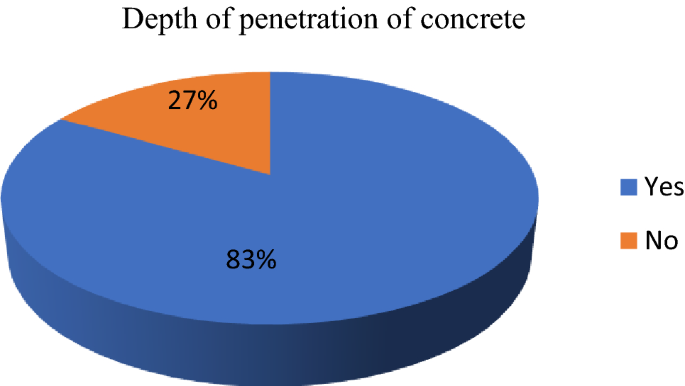
Depth of penetration of concrete
-
2.
Figure 14 shows the most common machine/tool used to chip concrete is the hammer and hand tool.
Fig. 14 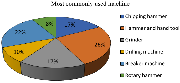
Machines used for concrete chipping
-
3.
Figure 15 shows the responses for the easiest machine to chip concrete.
Fig. 15 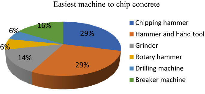
Easiest machine to chip concrete
-
4.
The difficulties that the workers face when using the above machines?


The most difficulties faced by the operator by using the available machines are the vibration, weight and the scattering of chips.
-
5.
Minimum time taken to chip 1 m2 concrete using the hammer and hand tool was recorded to be approximately 7 min.
-
From the survey that was conducted on the employees, feedback on the newly developed concrete chipping machine was also taken and the results were as follows;
-
-
6.
All employees agreed that this machine was easier to use than all other machines given in Table 6.
-
7.
It was found that the prototype developed was slightly noisy although the other aspects are comparatively better than the machines available in the market, thus improvements in this aspect have to be done in the future.
-
8.
The time taken to chip 1 m2 concrete using the prototyped concrete chipping machine was found to be approximately 2.30 min that is a saving of about 4 min per square meter.
7 Conclusion
Concrete chipping is a process carried out in order to increase the adherence of the concrete and the mortar before the plastering process. Machines available in the market had several issues, thus a new design was introduced. With the new machine, the following goals were achieved:
-
Considerable time was reduced in order to chip concrete.
-
Fewer safety issues when compared to the use of grinders, breaker machine.
-
Less power is consumed compared to breaker machines.
-
The concrete structure will not be completely damaged unlike when using a breaker machine.
-
Highly skilled labor is not required to operate this machine.
On a survey carried-out using the prototyped concrete chipping machine at several construction sites, it was found that, an approximate time saving of 55% can be achieved, when compared with other hand tools.
ANSYS software can be used to determine the stress distribution before the machine is prototyped. This gives the designer an idea of the necessary changes that have to be made before prototyping, thus reduced wastage of time and money. The attachment to the grinder would be a suitable inclusion to chip concrete. Unlike the use of hand tools, concrete breaking machines, angle grinders with grinding discs, and the grinding machine with the attachment (concrete chipping machine) have proven to be a lot safer to use, efficient and less time-consuming. Further improvements of this machine would be to reduce the weight of the attachment and to develop various replaceable sizes of the attachment (with different tool sizes) to facilitate the operator to change the attachment depending upon the surface it is being used.
References
Courard L (2018) Parametric study for the creation of the interface between concrete and repair products. Mater Struct 2000(33):65–72. https://doi.org/10.1007/BF02481698
Garbacz A, Gorka M, Courard L (2004) Effect of concrete surface treatment on adhesion in repair systems. Magn Concr Res. https://doi.org/10.1680/macr.2005.57.1.49
Bissonnette B, Vaysburd A, VonFay K (2012) Best practices for preparing concrete surfaces prior to repairs and overlays. Trid.trb.org. https://trid.trb.org/view/1290821
Godaire D, VonFay K, Gumina T (2005) Bond quality of fiber reinforced polymer concrete strengthening systems. U.S. Department of the Interior Bureau of Reclamation, Denver
Carter L, Wales C, Varley I, Telfer M (2008) Penetrating facial injury from angle grinder use: management and prevention. Head Face Med. https://doi.org/10.1186/1746-160X-4-1
Different Types of Concrete Grades and their uses | Base Concrete. Baseconcrete.co.uk. https://www.baseconcrete.co.uk/different-types-of-concrete-grades-and-their-uses/. Accessed 15 July 2018
Reinforcement Cement Concrete (2000) Building works, vol I. Colombo: ICTAD, p 55
Devadas M, Pillai U (2003) Reinforce concrete design, 2nd edn. Tata McGraw-Hill, New Delhi, pp 170–171
Khurmi R, Gupta J (2005) A textbook of machine design, 14th edn. Eurasia Publishing House, New Delhi
Valiente Blanco I, Díaz J, Lucero D, Jimenez E (2018) Machine theory. Ocw.uc3m.es. http://ocw.uc3m.es/ingenieria-mecanica/machine-theory/lectures-1/cams-design
Rothbart H (2004) Cam design handbook. McGraw-Hill, Hightstown, pp 84–94
Author information
Authors and Affiliations
Corresponding author
Ethics declarations
Conflict of interest
The author declares that there is no conflict of interest.
Additional information
Publisher's Note
Springer Nature remains neutral with regard to jurisdictional claims in published maps and institutional affiliations.
Rights and permissions
About this article

Cite this article
Weragoda, D.M. Concrete chipping machine: an attachment to the grinding machine. SN Appl. Sci. 1, 1321 (2019). https://doi.org/10.1007/s42452-019-1285-7
Received:
Accepted:
Published:
DOI: https://doi.org/10.1007/s42452-019-1285-7