
Abstract
Starting from the past or medieval period to the present day situation, history clearly indicates that the development of a region was and even today is function of a good transportation network. In the present day, society demands for an efficient and unobstructed road network after experiencing major issues or problems like traffic congestion, delay, pollution, increased vehicle operating cost and road accidents. Keeping in mind the above needs and constraints to traffic movement, an analysis of a digitized road network of the concerned city/town can be one of the best remedy to solve the problems. Such analysis is best suited in ArcGIS, Geographic Information System (GIS) software for creating, analyzing and compiling maps for obtaining information. In the present study an effort was made to prepare a road network map of Guwahati city and to find the shortest route between two places by proper analysis and digitization of its existing road network system in order to solve the traffic related problems to great extent. Network Analyst is a special analysis tool in ArcGIS which not only scrutinize the closest facility available in network of digitized interconnected lines but also facilitates in optimizing route during floods and emergency responses. One of the best models that can be generated through Network Analysis is the shortest route between required origin and destination points. The analysis is done based on input of certain network attributes like traversing distance, time and cost of travel, barriers, vehicle restrictions etc. All the important roads connecting each other within the Guwahati City were digitized in the GIS environment and proceeded further to serve the purpose.
1 Introduction
The Indian highway network (IHN) is one of the busiest road networks in the world, constituting 2% of all roads in India but handling 40% of the total road traffic as of 2010 [1]. Traffic congestion occurs in certain parts and stretches of roads in Guwahati. Inadequate parking space, exorbitant bus, auto rickshaw, rickshaw and taxi fares, time-consuming and uncomfortable journey, frequent accidents are the causes and consequences related to traffic in the city. Flood inundation and water-logging problems are also faced in several ward of Guwahati Municipal Corporation area during the rainy season. Rapid urbanization with increased housing more rooftops, driveways, streets and other impervious or hard surfaces [2]. Hence to overcome the problems and to keep up sustainability, proper analysis of the present road network is very much crucial to help humanity to reach their destination with ease, reduced cost and time etc.
A GIS is an organized collection of computer hardware, software, geographic data, and personnel to efficiently capture, store, update, manipulate, analyze, and display all forms of geographically referenced information. ArcGIS Network Analyst enables users to dynamically model realistic network conditions, including turn restrictions, speed limits, height restrictions, and traffic conditions, at different times of the day [3]. ArcGIS proved to be one of the most user friendly, effective and time-saving tools in the field of both traffic engineering and transportation planning.
2 Methodology
For the network analysis of Guwahati City, a street basemap was added in ArcGIS software from the Google Earth satellite imagery and geo-referenced to get the co-ordinates. Geo-referencing involves image alignment in a co-ordinate system [4]. The study area is being enlarged to an easily workable scale as shown (Fig. 1).

Image showing the enlarged study area (Guwahati city) marked as red color (Google Maps 2018)
Layers are the mechanisms used to display geographic datasets in ArcGIS. For the analysis, the layers were being categorized as major road (mainly the Highways) and minor road (city roads connecting the highways and other urban localities), lanes and by-lanes in addition to wards. The table of contents lists all the layers on the map and shows what the features in each layer represent [5]. After successful creation, the base map digitization for each layer was done to form a skeleton of the prevailing road network. Digitization is process of making an electronic version of a real world object or event, enabling the object to be stored, displayed and manipulated on a computer, and disseminated over networks [6]. The entire GMC area is divided into 31 municipal wards and each municipal ward is further divided into 2, 3 or 4 Area Sabhas (subwards). A ward map was drawn as a layer over the Guwahati city based on the official GMC (Guwahati Municipal Corporation) map (Figs. 2, 3).

Road network map of Guwahati city drawn in ArcGIS software

Ward map of Guwahati city
3 Analysis
Network analysis in GIS rests firmly on the theoretical foundation of the mathematical sub disciplines of graph theory and topology. The most common and familiar implementations of network models are those used to represent the networks with which much of the population interacts every day: transportation and communications networks [7]. Routing is the act of selecting a course of travel, and it is arguably the most fundamental logistical operation in network analysis. Although network analysis in GIS has been largely limited to the simplest routing functions, the recent past has seen the development of object oriented data structures, the introduction of dynamic networks [8], the ability to generate multi-modal networks, and the use of simulation methods to generate solutions to network problems. There are, of course, many important network design problems that are very difficult to solve optimally due to their combinatorial complexity [9]. To allocate and provide urban facilities in an area with complex road network, determination of the shortest route as well as travel demand (trips generated and attracted) from the facility to the concerned area is a must. Generating the shortest path between two locations in a road network is a problem that can be solved by various map services and commercial navigation products [10]. There are several extremely efficient algorithms for determining the optimal route, the most widely cited of which was developed by Edsgar Dijkstra (in the year 1959).
The algorithm [11] is represented in brief as below:
where V is a set of vertices and E is a set of edges.
Dijkstra’s algorithm keeps two sets of vertices:
-
S the set of vertices whose shortest paths from the source have already been determined.
-
V-S the remaining vertices.
-
The other data structures needed are:
-
D array of best estimates of shortest path to each vertex
-
Pi an array of predecessors for each vertex
The basic mode of operation is:
-
1.
Initial is d and pi.
-
2.
Set S to empty.
-
3.
While there are still vertices in V-S.
-
a.
Sort the vertices in V-S according to the current best estimate of their distance from the source.
-
b.
Add u, the closest vertex in V-S, to S.
-
c.
Relax all the vertices still in V-S connected to u.
-
a.
Pseudo code for Dijkstra’s Algorithm:
-
Distance [s] ← 0 (distance to source vertex is zero)
-
for all v ∈ V–{s}
-
do distance [v] ← ∞ (set all other distances to infinity)
-
S ← ∅ (S, the set of visited vertices is initially empty) Q ← V (Q, the queue initially contains all vertices) while Q ≠ ∅ (while the queue is not empty)
-
do u ← min distance (Q, distance) (select the element of Q with the min. distance)
-
S ← S ∪ {u} (add u to list of visited vertices) for all v ∈ neighbors[u]
-
do if distance [v] > distance [u] + w(u, v) (if new shortest path found)
-
then d[v] ← d[u] + w (u, v) (set new value of shortest path)
-
(if desired, add trace back code)
-
return dist.
To run the analysis over the digitized road network, a network geo dataset was created which resulted in a layer consisting of the junctions and edges connected topologically to each other. Ward analysis was done using Intersection tool to get the statistics of all the categorized roads created as layers. The origin and destination points were selected to solve the network for determination of the shortest route and to serve the purpose of our study (Fig. 4).

Junctions and edges of the digitized road network generated by network analyst toolbar in ArcGIS
An attribute table, tabular arrangement of meaningful data, of the digitized road network was generated to get the latitudes and longitudes (in degrees), road ID and name and the distances (in meters) between the junctions (or origin to destination) (Fig. 5, Table 1).

Image showing the attribute table of the digitized road network of Guwahati city
4 Results and Discussions
The results can be interpreted as follows:
Guwahati city has been divided into 31 main municipal wards which are further subdivided forming a total of 90 wards. From the ward-road network analysis, it has been seen that-
-
A.
Ward 22C has the largest area (9.954 km2) and Ward 12B has smallest area (0.103 km2). The 3 major roads pass through the 44 wards of Guwahati city out of which the ward 1B covers the maximum number of major roads (2) with a total length of 7.873 km. 48.88% of the wards have the major roads (Figs. 6, 7).
Fig. 6 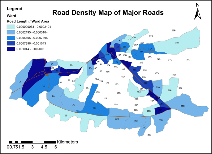
Map showing density of major roads ward wise in ArcGIS
Fig. 7 
Map showing density of minor roads ward wise in ArcGIS
-
B.
All the minor roads pass through 85 wards of the city out of which the ward 10A holds the maximum number of minor roads (9) with a total length of 4.554 km. The lanes and by-lanes cover up all the wards among which ward 6C has highest number of lanes (148) traversing throughout with a total length of 37.305 km. 94.44% of the wards have the minor roads.
-
C.
Lanes cover up all the wards.


But when it comes to existing road density or the number of specific roads in all the wards, more than the half of the total wards (90 wards) doesn’t have sufficient roads. Such deficiency of road networks is mostly seen in the outer areas cum rural urban of the city including the rural villages. Limited roads and poor network is one of the reasons for traffic congestion. Traffic congestion leads to delay of vehicles, increased vehicle operating cost, increase in air and sound pollution, emission of poisonous gases like Carbon Monoxide (CO), road accidents, warming up of surrounding urban area, human frustration leading to road rage etc. From the field survey, it has been observed that for feeder trips, both transit and Para transit use some other routes other than the shortest route as per GIS. The reasons are numerous like transport movement policy, poor pavement conditions, unawareness of non-commuters etc. (Fig. 8).

Map showing density of lanes and by-lanes ward wise
A network analysis layer stores the inputs, properties, results of a network analysis and is always performed on network dataset. Network analysis in GIS rests firmly on the theoretical foundation of the mathematical sub disciplines of graph theory and topology. This paper is presented taking into account the route analysis layer and the analysis is based on real time network problems independent of the hierarchy (major roads, minor roads and lanes).GIS networks consist of interconnected lines (known as edges) and intersections (known as junctions) that represent routes upon which people, goods, etc., can travel. Network analysis helps in modeling as well as planning and management of moderate to heavy traffic routes. One common type of network analysis is finding the shortest path between two points. Junctions (or nodes) and edges have certain attributes affixed to them which help in modeling. Edges and junctions are topologically connected to each other-edges must connect to other edges at junctions, and the flow from edges in the network is transferred to other edges through junctions.
Determination of the shortest route between the origin and destination using the GIS Network Analyst will not only help the tourists or business entrepreneurs to access the tourist places or the trade centers with ease but it will also reduce cost and avoid traffic congestion resulting in less emission of pollutants. Dijkstra (1959) proposed a graph search algorithm that can be used to solve the single-source shortest path problem for any graph that has a non-negative edge path cost [12]. Network attributes are properties of the network elements that control movement over the network and helps in finding the shortest route based on type of attribute such as distance, vehicle restrictions, turn restrictions etc. This paper presents the shortest route based on the assumptions that traffic congestions are not considered and the calculations are based on road distances (Figs. 9, 10; Table 2).

Image showing the shortest route between Khanapara old ASTC point to Jalukbari flyover point (shown by blue color) in ArcGIS

Image showing the shortest route between Paltan Bazar to Lokhra Bamunpara Chowk (shown by blue color) in ArcGIS
-
D.
To travel from Nepali Mandir, Paltan Bazar to the ISBT, Guwahati there are three relatively shorter routes, the distance and via of which are given below:
-
a.
via Lal Ganesh, Distance = 12 km
-
b.
via Fayez Ahmed Road, Distance = 9.3 km
-
c.
via Dhirenpara Road, Distance = 8.9 km
-
a.
Division of the different types of vehicular road traffic into alternative shortest routes on the basis of operating characteristics and mileage performance of vehicles and proper revision of the transportation policy of the concerned can tackle the traffic congestion.
5 Conclusion
Thus Network Analysis is one of the most powerful tools to deal with the real time transportation problems. It is reliable, user friendly and efficiently solves the network problems. It has replaced the conventional methods of analyzing and saves lot of time and work. It emerged out as the helping hand in the field of transportation planning, origin and destination studies. It has high potentiality in analyzing the closest facility and service areas in a network. Ward analysis is a another easiest way to know the present density and number of roads in service which in turn would help in transportation planning keeping in consideration the various aspects. Information about the shortest route would help the drivers and road users to save the transportation cost, time and avoid traffic congestions in commuter routes by diverting the excess flow through less travelled shorter routes. Road structure improvement of the shortest routes by widening and imposing restrictions to parking would be a beneficial factor. Signal timing should be adequate for the intersecting shortest routes to serve maximum flow and avoid delay. Law enforcement should be strictly implemented on such routes to maintain discipline and stimulate the urban development. Increasing the number of minor roads (provided those are shortest) in wards concerned depending on the demand for transportation to-
-
1.
Avoid congestion in the existing single routes.
-
2.
Increase connectivity of the rural urban with the major road to avoid entry into the Central Business District (CBD).
As a whole, it can also be concluded that GIS has a lot of applications directly or indirectly in the field of transportation as the studies about the existing road network problems as their solutions can enhance the economy of a locality to a great extent. Implementation of the advanced technologies can be beneficial to maintain the sustainability and transportation related GIS tasks should be preferred for better output in future.
6 Research and Development (R&D)
The work has been carried out considering distance as impedance. In many cases, it has been seen that, the shortest route in terms of distance doesn’t always mean the shortest one in terms of time. One of the prime reasons is the huge flow of vehicles through the only shortest route leading to time consumption. Further work with much improved accuracy and efficiency should be carried out considering time as impedance factor. Traffic Data in real time for different routes has to be obtained from Google maps. Google Maps Traffic uses GPS signal data from smartphones in order to sustain such an immense algorithm [13]. It calculates the speed of the users which helps in knowing the affected routes. The shortest route algorithm can preserve the travel time with 20–22%, depending on the travel distances [14]. Although finding the shortest route between two points might be a known case for the mass using the Google Maps, but it gives long range transportation planning solutions like determining the zones/areas where urban activities like shopping malls, schools/colleges, offices, industries, health centers, recreational centers etc., has to be established at a specific location depending on the travel demand and the availability of required class of roads to make accessible to the people within as well as outside the locality. Since there are many places around the globe where internet/mobile connectivity is either less or nil, the shortest route map becomes the replacement of Google Maps. In addition to that, research work can be carried out to determine the path for establishing higher modes of public transport like Light Rail Transit (LRT), Metro trains, Bus Rapid Transit (BRT) etc. Also, the choice of shortest route due to variation in traffic during different times of the day, seasons, climate, festivals etc., and during emergency situations like accidents, fire etc., can be studied.
References
Mukherjee S (2012) Statistical analysis of the road network of India. Pranama J Phys 1:2. https://doi.org/10.1007/s12043-012-0336-z
Barman P, Goswami DC (2009) Floodzone of Guwahati municipal corporation area using GIS technology. In: 10th ESRI India user conference 2009
Kumar P, Kumar D (2016) Network analysis using GIS techniques: a case of Chandigarh city. Int J Sci Res (IJSR) 5(2):409–411
Herbei MH, Ciolac V, Smuleac A, Nistor E, Ciolac L (2010) Georeferencing of topographical maps using the software ArcGIS. Res J Agric Sci 42(3):595–606
Laixing L, Deren L, Zhenfeng S (2008) Research on geospatial information sharing platform based on ArcGIS server. In: The International archives of the photogrammetry, remote sensing and spatial information sciences, vol 37, Part B4, pp 791–795
Manjula KR, Jyothi S, Varma AK (2010) Digitzing the forest resource map using ArcGIS. IJCSI Int J Comput Sci Issues 7:300
Kurtin KM (2007) Network analysis in geographic information science: review, assessment and projections. Cartogr Geogr Inf Sci 34(2):103–111
Sutton JC, Wyman MM (2000) Dynamic location: an iconic model to synchronize temporal and spatial transportation data. Transp Res Part C Emerg Technol 8(1–6):37–52
Magnanti TL, Wong RT (1984) Network design and transportation planning: models and algorithms. Transp Sci 18(1):1–55
Lingkun W, Xiaokui X, Dingxiong D, Gao C, Andy DZ, Shuigeng Z (2012) Shortest path and distance queries on road networks: an experimental evaluation. VLDB 5(5):406–417
Khaing O, Wai H, Myat E (2018) Using Dijkstra’s algorithm for public transportation system in yangon based on GIS. Int J Sci Eng Appl 7(11):442–447
Akpofure ON, Paul AN (2017) Anapplication of Dijkstra’s Algorithm to shortest route problem. IOSR J Math (IOSR-JM). e-ISSN: 2278-5728
Hajnalka KA (2018). Road network analysis using GIS techniques in the interest of finding the optimal routes for emergency situatons. Case study: CLUJ-NAPOCA (ROMANIA), Geographia Napocensis Anul XII, nr. 1, 2018
Ahmed S, Ibrahim RF, Hefny HA (2017) GIS based Network Analysis for the Roads Network of the Greater Cairo Area. In: Proceedings of the international conference on applied research in computer science and engineering ICAR’17, vol 2144, no 1 at http://ceur-ws.org
Author information
Authors and Affiliations
Corresponding author
Ethics declarations
Conflict of interest
On behalf of all the authors, the corresponding author states that there is no conflict of interest.
Additional information
Publisher's Note
Springer Nature remains neutral with regard to jurisdictional claims in published maps and institutional affiliations.
Rights and permissions
About this article

Cite this article
Das, D., Ojha, A.K., Kramsapi, H. et al. Road network analysis of Guwahati city using GIS. SN Appl. Sci. 1, 906 (2019). https://doi.org/10.1007/s42452-019-0907-4
Received:
Accepted:
Published:
DOI: https://doi.org/10.1007/s42452-019-0907-4