Abstract
Augmented bricklaying explores the manual construction of intricate brickwork through visual augmentation, and applies and validates the concept in a real-scale building project—a fair-faced brickwork facade for a winery in Greece. As shown in previous research, robotic systems have proven to be very suitable to achieve various differentiated brickwork designs with high efficiency but show certain limitations, for example, in regard to spatial freedom or the usage of mortar on site. Hence, this research aims to show that through the use of a craft-specific augmented reality system, the same geometric complexity and precision seen in robotic fabrication can be achieved with an augmented manual process. Towards this aim, a custom-built augmented reality system for in situ construction was established. This process allows bricklayers to not depend on physical templates, and it enables enhanced spatial freedom, preserving and capitalizing on the bricklayer’s craft of mortar handling. In extension to conventional holographic representations seen in current augmented reality fabrication processes that have limited context-awareness and insufficient geometric feedback capabilities, this system is based on an object-based visual–inertial tracking method to achieve dynamic optical guidance for bricklayers with real-time tracking and highly precise 3D registration features in on-site conditions. By integrating findings from the field of human–computer interfaces and human–machine communication, this research establishes, explores, and validates a human–computer interactive fabrication system, in which explicit machine operations and implicit craftsmanship knowledge are combined. In addition to the overall concept, the method of implementation, and the description of the project application, this paper also quantifies process parameters of the applied augmented reality assembly method concerning building accuracy and assembly speed. In the outlook, this paper aims to outline future directions and potential application areas of object-aware augmented reality systems and their implications for architecture and digital fabrication.
1 Introduction
The high environmental impact of the construction sector and the perceived lack of increased productivity underscore the interest and investment in the development of digital fabrication technologies for the innovation of construction processes. Approaches to digital fabrication, in particular, combining methods of computer-aided design and robotic fabrication, have shown great potential for the integration of architecture and engineering design practices establishing a highly effective interplay between digital design and conventional construction processes (Dörfler et al. 2016; Gramazio et al. 2014). However, the challenge of digital fabrication on a building scale is not merely the full automation of single tasks. Recently, a stream of research has emerged in architecture, recognizing the high diversity of tasks associated with the domain of architecture and construction (Vasey et al. 2016). This stream foresees a digital building construction methodology, where skilled workers and machines will share diverse tasks in the same work environment and collaborate towards common goals, combining the best of both their strengths and still fully exploiting a digital design-to-production-workflow (Stock et al. 2018). Collaborative human–machine systems are defined by a distribution of decision-making processes, combining the advantages of a machine with human knowledge, skills, and dexterity. Whereas humans have a fast ability to interact in estimation on patterns and complex environments (Polanyi 1985), machine logic exceeds human capacities with respect to precise calculations and data processing, for example, processing precise measurements resulting from machine vision). Hence, the concept of human–machine interaction is of increasing interest for architecture, engineering and construction (AEC) industry as well as the academic community to achieve higher performance as well as enable socially sustainable semi-autonomous concepts and robotic processes (Ejiri 1996)
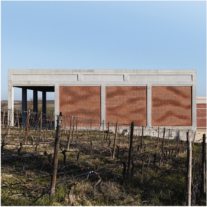
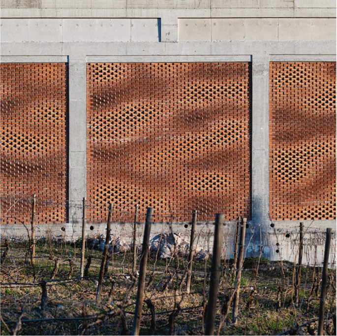
Recent developments of such collaborative human–machine systems in architecture have begun to explore the potentials of Augmented Reality (AR) systems, focusing on manual fabrication and assembly tasks (Kohn and Harborth 2018; Büttner et al. 2017; Billinghurst et al. 2008; Molineros and Sharma 2004) illustrating the potential to improve time efficiency and costs of on-site work tasks by up to 50% (Chu et al. 2018). When using AR systems for guiding manual construction processes, one of the major drawbacks of current off-the-shelf AR systems (i.e., HoloLens, MagicLeap) is the insufficient accurate alignment of the digital model with the physical environment and an unsatisfying context awareness, i.e., for understanding the as-built condition in relation to the digital plans. To overcome the alignment limitations (Bostanci et al. 2013), researchers have thus proposed solutions that either use markers (Jahn et al. 2019; Hübner et al. 2018), restrict the user to specific regions (Welch et al. 2001), or rely on Global Positioning Systems (GPS) (Chung et al. 2016). However, these solutions still do not meet the requirements for building accuracy and lack of options for measurements and process-specific feedback. Therefore, this paper proposes to use a custom-built augmented reality system that applies a novel approach with markerless object detection for pose estimation (Sandy and Buchli 2018). This system provides the 3D registration of discrete objects together with highly accurate pose estimation, to visually guide humans executing manipulation procedures in real time via a screen, promising to offer improvements in accuracy, feedback, and speed in comparison to off-the-shelf AR systems. By integrating findings from the field of human–computer interfaces and human–machine communication, this research establishes a craft-specific human–computer interactive fabrication system. This system aims to enable a highly dynamic and accurate AR-guided manual assembly process, in which a novel intent-based user interface aims to combine explicit machine knowledge operations (i.e., the accurate 3D registration of bricks in real time) with implicit craftsmanship knowledge, (i.e., the implicit craft-specific knowledge as well as the dexterity needed for the proper handling of mortar). The augmented manual bricklaying has been applied and validated in a real-scale building project—a fair-faced brick-work facade for a winery in Greece in 2019. This project provided the opportunity to examine the implications, potentials, and challenges of applying such AR technology in a real-world construction scenario. The facade constructed of 13596 individual bricks is currently the biggest example of an on-site construction using a human–computer interactive system with an augmented reality interface (Fig. 1). The remainder of this paper is organized as follows: recent progress in augmented reality fabrication is overviewed in Sect. 2. Then the interaction concept and methodology are outlined in Sect. 3. In Sect. 4, the developed concepts are applied to an augmented bricklaying scenario with human–computer interaction as a case study to present their practical relevance and implementation. Finally, the results and conclusion of this research are discussed in Sects. 5 and 6.
2 Context
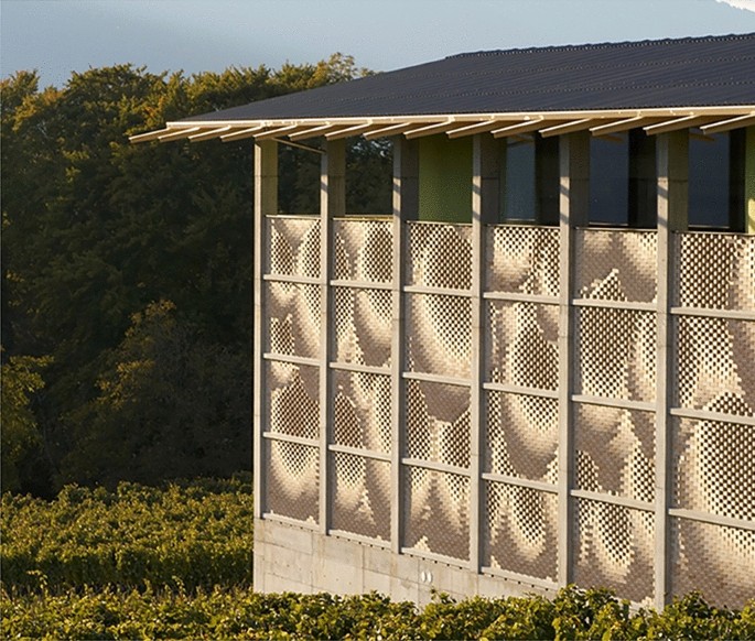
Projects such as the Gantenbein winery (Fig. 2) in 2006 paved the way towards enabling robotic fabrication to bridge the virtual and the physical realm weaving digital-design data into material building processes (Gramazio and Kohler 2008). Despite the progress made since then in robotic fabrication, there remains a lack of transferability of in situ robotic processes to real-world construction scenarios. An example of such are unstructured work environments such as the construction sites, which still require human dexterity and knowledge to respond successfully and intuitively to material inconsistencies and complex changing environmental conditions.
Moreover, the setup costs, logistics, and necessary hardware, infrastructure, and technical know-how needed are barriers to implement robotic construction directly on the construction site successfully. While research has shown the potentials of using context-aware mobile robots for in situ fabrication (Dörfler et al. 2016; Feng et al. 2015), recent technology advancements in the domains of human–machine interaction and augmented reality, point towards an alternate yet synergistic strategy for digitalized building construction in a complex on-site context. It is now possible to equip construction workers and craftsmen with an ecology of tools, in particular, sensors and AR interfaces, to entirely fabricate in situ, establishing a direct link between the digital design environment and a physical process, achieving a precision close to industrial robots with an entirely different technological approach.
The possibilities to use AR as a guide for craftsmen in the manual manufacturing process (Nee et al. 2012) have been shown recently by a growing number of research endeavors. One seminal project in the field was the “Stik pavilion” (2014) by the Digital Fabrication Lab of the University of Tokyo using AR technologies to guide human actions via projection-based mapping to inform builders about a designated building area (Yoshida et al. 2015). Another projection-based augmented reality project, used to visualize potential material behavior during the fabrication process, is the project “Augmented materiality” (Johns 2017) by Greyshed. A more recent example is the “Collaborative Robotic Workbench CRoW” by ICD Stuttgart (Kyjanek et al. 2019), which combines a KUKA LBR IIwa robotic arm with an augmented reality headset using AR as a process-specific robotic control layer. AR-guided assembly strategies have later been commercially exploited by the company Fologram. Fologram uses AR headset technology to allow operators to see instructions for manual assembly via a virtual holographic 3D model in space. With Fologram’s approach and projects, they demonstrate how fabrication within a mixed reality environment can enable assisted unskilled construction teams to assemble complex structures in a relatively short amount of time (Jahn et al. 2018; Jahn and Wit 2019). This commercially available system uses holographic outlines for spatially visualizing geometry, and promises to be at ease-of-use. While this growing number of examples show the enormous potential of such AR fabrication, all of the systems discussed show significant technological and conceptual gaps. Most importantly, this lack includes limited context-awareness with no feedback, insufficient localization accuracy to guide construction tasks, as well as the inability to register and measure the as-built structure with sub-centimeter accuracy. Additionally, a custom craft-specific user interface for fabrication is rarely developed even though most off-the-shelve augmented systems include the possibilities for such functionalities in their application programming interfaces (API) (Lafreniere et al. 2016).
3 Methods
3.1 AR-guided assembly system setup
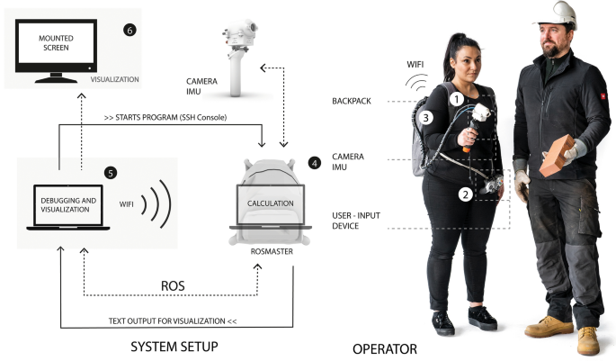
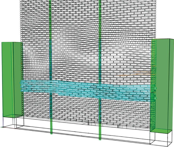
Augmented bricklaying explores the construction of a complex geometrically differentiated fare-faced brick facade through an intent-based augmentation system. The AR setup consists of a tracking and visual guiding system, combining an object-aware tracking procedure with a craft-specific user interface. The tracking system enables to register discrete objects, in this particular case, bricks, with high precision in 3D space. For this, it uses edge-detection to incrementally track and estimate the location of the objects (for technical details and implementation, refer to Sandy and Buchli 2018). Therefore, in extension to recently shown augmented reality fabrication systems, the digital model can not only be projected as a hologram, as, i.e., seen in “Holographic Construction” (Jahn et al. 2019), but the as-built data of registered members of a structure being built can be directly registered and fed back to the digital model. Due to this highly precise object tracking and registration system, errors and deviations between the as-planned and the as-built data can be estimated in real time, and the dynamically adapted instructions can be visually communicated directly via the custom user interface to the bricklayers using the system. Initially, the system was intended to be a one-person wearable AR system but due to technical difficulties, evoked by the substantial movement of a bricklayer, and the partial obscuring of the camera image by hands, this workflow had to be reconsidered. Therefore, the system was extended to a two-person process, a bricklayer, and an operator. The bricklayer is responsible for laying mortar and bricks. The operator carries and uses the AR system to direct the bricklayer. Both share a movable screen as a visualization platform and communicate throughout the process. To place each brick in the 3D-complex masonry facade correctly, the bricklayer needs to understand the 3D position (position and rotation) of each brick in relation to its neighboring bricks. Therefore, the operator is equipped with a handheld camera and an inertial measurement unit (IMU) (Fig.3: 1), a so-called “eye-in-hand” system (Schmalstieg and Höllerer 2016), for dynamic determination of user position (Fig.3: 1). Furthermore, the operator carries a portable joystick used as a sensory-input device (Fig.3: 2). The functionalities exposed through a joystick user-input device allow the operator to accept an already placed brick, reverse one brick, or delete an already accepted brick. Two portable laptops (Fig.3: 4, 5) support each AR system, whereas the operator carries the calculation laptop in a backpack. It is connected to the camera and IMU and communicates via Ethernet through ROS (Quigley et al. 2015) with the second laptop, which is solely used for visualization (Fig.3: 5). These two processes (calculation and visualization) are split to avoid delay in processing as well as to provide a cable-free portable laptop to allow the operator to move as freely as possible. The local meta-data from the digital model is correctly anchored in space via object detection and overlaid with the camera image stream. This combination of virtual and real stimuli is visualized in situ on the 27” mounted screen (Fig.3: 6). To dynamically sense and measure the 3D position and rotation of the bricks, the AR system uses edge-detection to incrementally track and estimate the location of features of the masonry structure. The system additionally tracks larger objects on the work site; in this case, the concrete frame and vertical struts, which serve as global reference geometry and ensure the avoidance of error accumulation and that the wall maintains sufficient alignment with the existing building structure over the course of construction (Fig. 8). The system depends on the dimensions of these global objects of reference to be precisely measured and digitized before construction (Fig. 8).
3.2 Craft-specific user interface
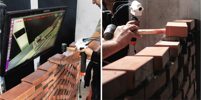
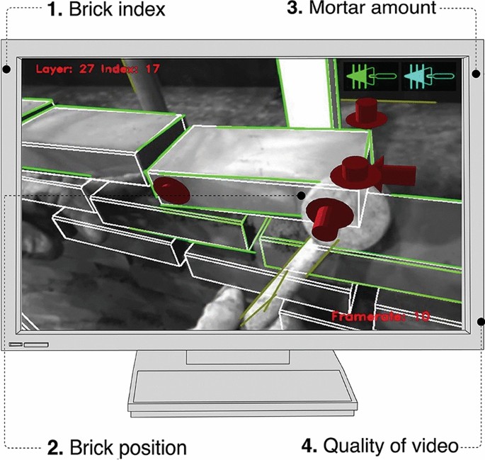
The development and design of a bespoke craft-specific user interface (UI) was crucial to the successful application of the AR system in building the facade. Augmented bricklaying is divided into three temporal differentiated main task sequences for bricklayers to follow. This visual feedback system guides the bricklayer and operator by providing visual instructions for laying bricks in their correct relative locations with high geometric precision to the tracked structure as defined by the computational model in real time. The UI design uses gamification elements in the interface design, which are derived from craft-specific gestures familiar to the bricklayer. Traditionally, bricklayers adjust bricks not via free-hand rotation but by tapping them with their trowels in x/y/z-plane to reorient them. Therefore, the most crucial information for a bricklayer is the horizontal and vertical location of the hit, as well as the strength of the tap. This information is visualized by vertical and horizontal arrows, in which the arrow’s size is directly linked to the required tapping strength (Fig. 4). The exact position of the arrows results from the visual–inertial object-tracking algorithm, whereas the length of the arrow indicates the strength of the tap, resulting from the difference between the target position and estimated pose position. The design included the differentiation of the brick courses with varying mortar heights and alternating rotations of the individual bricks. Additional icons convey to the operator how much mortar should be used for the next brick by showing one of three types of abstracted trowels (S, M, L) (Fig. 5). As the wall is perforated, the interface indicates the left and right mortar amount. The bricklayer learned over time how much mortar corresponded to each icon, and intuitively chooses the correct amount of mortar per brick.
The temporal sequence of augmented masonry tasks was split into three main steps. First, the bricklayer was instructed about the approximate amount of mortar per brick, indicated with an abstract trowel from full to empty. Second, similar to the main type of feedback in conventional AR systems, the bricklayer is shown a red outline of the desired position of the brick. This outline gives the bricklayer a fast understanding of the rough placement and rotation of the element. When the brick is approximately placed, the operator accepts the position via manual sensory input, and the interface switches to fine adjustments. In this stage, arrows appear, and the bricklayer uses the trowel to hit on the positions indicated by red arrows with the strength indicated until they vanish. The arrows vanish if an accuracy between estimated and desired brick 3-D pose is 4 mm or lower. A lower error acceptance (<2 mm) was tested, but the system’s sensitivity in combination with material viscosity and human dexterity led to a long execution time, as bricklayers spend too much time trying to adjust the bricks till the arrows vanished. Therefore, 4 mm proved to be the ideal ratio. Every brick was indicated with an index number to allow the bricklayer to self-control during the process and to avoid skipping of bricks within one row. To bring this technology from the lab onto the construction site, several different visualization setups were initially explored and compared, utilizing screens, tablets (openCV and OpenGL), and augmented reality head-mounted displays (Magic Leap). For the specific case study (outdoor, bright), a screen-based system proved to be the most efficient visualization platform, as the permanent display offered the possibility to communicate between craftsmen and even to other non-AR audiences. The brick wall was designed in Rhinoceros with a python-based script using Grasshopper and COMPAS (Van Mele et al. 2017). The position of each brick as well as the global reference geometry was saved via a text file which was read by the system. This file represented the connection between the digital design and the tracking system storing the sequence of each brick as well as the their desired target position. Additionally this text file could store supplementary information for each brick, which was then visualized during the augmented bricklaying process. This information included changes in brick geometry (half or full brick), mortar amount, index and row number. Throughout the building process, the list of additional information changed according to needs.
Craft-specific user interface: arrows indicate location and strength of the knocking to reposition the bricks (2). Bricks are indicated according to layer and brick-index per layer (1). Symbols show mortar amount per brick (3). Frame rate is indicated in the corner of the screen, informing the operator about light conditions (4)
4 Case study
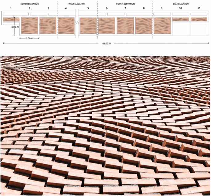
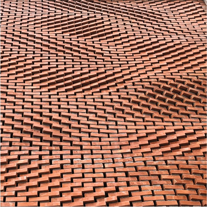
The final implementation of the proposed system was used to build a double fair-faced geometrically differentiated permeable masonry façade for the Kitrus vinery in Katerini/Greece. The structure included eight infill masonry facade elements of 5 by 5 m and three small-scale facade elements of \(5 \times 3\) m resulting in a total of 245 m\(^2\) of brick façade (Fig. 7). Overall, a total of 13596 handmade bricks were used. To highlight the malleability of mortar and the flexibility gained by the AR fabrication system, the design exploited a differentiation of brick courses and varying mortar height (5 mm to 30 mm) using a time-based Perlin noise field. The rotation of the individual bricks was related to the amount of the underlying mortar (− 20 degree to + 20 degree rotation). The gap between the individual bricks was used to allow ventilation and light into the building and ranges from between 22 and 24 mm. The structural support system of the fair-faced non-load-bearing façade consists of four horizontal bars and custom-made metal blades cut, inserted and glued into the brick wall on-site.
4.1 On-site deployment
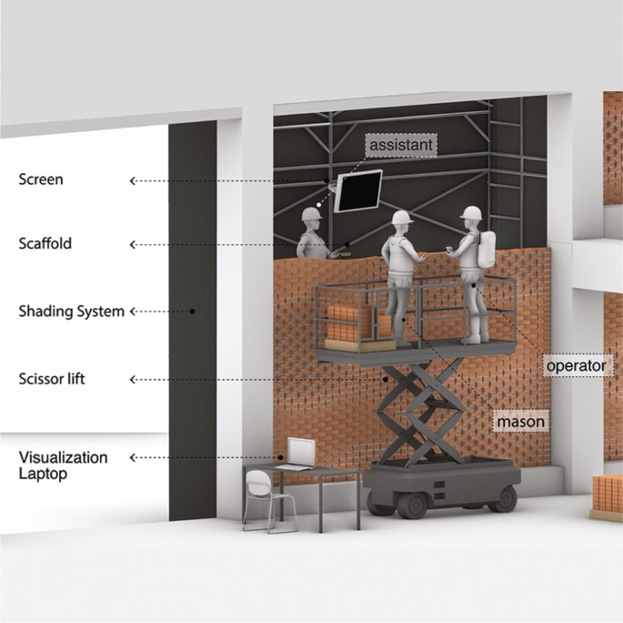
During the construction period, two teams were operating two individual augmented reality systems. Each team consisted of three workers: one bricklayer, one assistant, and one system operator (Fig. 6). The division of tasks was separated, whereas the bricklayer and the operator placed the individual bricks and operated the system, the henchman meanwhile cleaned the mortar joints and fulfilled side tasks such as mortar preparation. The screen was placed on an adjustable monitor arm and displayed virtual and real stimuli. Due to the height of the walls, the bricklayer and operator were stationed on a scissor lift, emphasizing the importance of a untethered approach. The front of the building was covered by a black, translucent shading system to avoid hard shadows on the bricks, which potentially could lead to tracking errors. The infill brick walls were circumscribed by a concrete framework (Fig.7), whereas the pillars were used as previously described global objects of reference for the tracking to minimize the accumulation of errors (Fig. 8).
5 Results
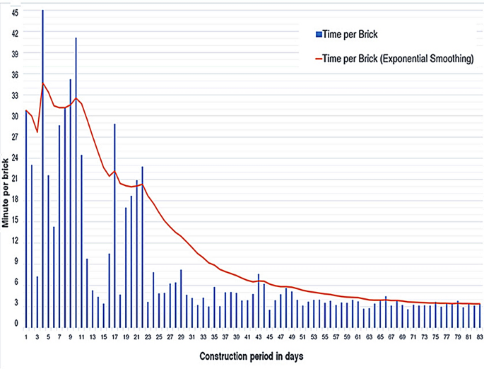
The construction period spanned over 3 months, experiencing extreme Mediterranean climates ranging from summer to winter outdoor conditions. The typical building speed for fair-faced brickwork is 1 min/brick for two bricklayers. The average time per brick after a learning and adjustment period with the custom augmented reality system was measured at 3 min/brick, which equals three times the amount of straight fair-faced brick masonry without rotation or vertical movement. The precision of the brick wall resulted in ± 5 mm local precision and ± 1 cm precision in an overall span of \(5 \times 5\) meters per facade element. These numbers are supported by the precise local connection points of each brickwall to the concrete frame (Fig. 8).
The custom user interface was analyzed via a post-session usability study,Footnote 1 and it proved to be very well received by the bricklayers. To analyze the user’s perception, we chose a self-reported metrics questionnaire for post-task rating analysis. Additionally, to a paper form questionnaire, respondents were observed and recorded during task completion to gather additional information. To avoid social desirability bias, the survey was taken anonymously and in solitude. The outcome of the questionnaire showed that novice users without assistance had a significantly worse experience of the system. Moreover, users with assistance reported that it required less training compared to non-assisted users. Another key finding is the fact that the interface was perceived similar to every group. The conducted study showed that novices require a short period of assisted introduction to the procedure to use the latter successfully. Nevertheless, the user’s performance increased noticeably over time (Fig. 9), regardless of the visualization platform or the assistance given. Unassisted novices, therefore, cannot use the system, as the number of errors made is too high. However, given that the user’s performance increased steeply over time, they become competent to use the system alone after a training period with an assistant. The “eye-in-hand” system, the handheld camera system, needed some learning time as the optical axis of the camera points into a different viewing direction and sometimes leads to a potential awkward translation of view direction. This fact indicates the potential advantage of head-mounted or phone displays. Nevertheless, after a learning period, the operator learns to use the system intuitively. The tracking system is stable for outdoor conditions and can be supported by the installation and registration of landmarks (concrete frame, vertical posts) to stabilize the system. Light conditions were another crucial parameter for the success of the system as direct sunlight can produce very sharp shadow lines disturbing the distinct detection of bricks. Shading the sun with a black textile prevented this, but as the object-based visual–inertial tracking is continuously developed, one can foresee that this problem will be solved in future releases.
6 Conclusion
This paper outlines and discusses the novel user interface tailored to the masonry craft, and the overall system design and integration into the building site’s layout and workflow. This technology has been tested in regard to accuracy (Fig. 8), in-door/outdoor conditions, and validated in terms of applicability, accuracy, and usability under outdoor conditions and on a large scale. The design explored the differentiation of brick courses with varying mortar heights and alternating rotations of the individual bricks (Fig. 10). Investigated through a large-scale demonstrator (Fig. 11), this paper presents different strategies for preserving consistent accuracy across a building site’s workspace to avoid error propagation. This paper shows first attempts in quantifying process improvements through AR for in situ assembly in the domain of building accuracy and assembly speed. For future development, the object detection algorithm could be included into off-the-shelf head-mounted displays (HMD) as an app-based application, including both, user-friendliness of HMD and context awareness of such tracking systems. In this case, if multiple craftsmen are working on a piece, a shared workspace would be necessary as communication is of utter importance on a construction site. Another future development would be the combination of the AR bricklaying processes with robotic fabrication, whereas a sensible task distribution between the craftsmen and the robot has to be developed. Significantly, the project extends digitalization to conditions and building scenarios that would resist a fully automated robotic process. Such an approach is particularly relevant to construction scenarios ill equipped with the necessary infrastructure to support an on-site robotic process or in material processes that benefit from tacit knowledge and craftsmanship or scalar restrictions, which are easier to overcome in an AR manual fabrication process. Another important quality of such an approach is social sustainability, the effective integration of traditional craftsmanship with digital fabrication processes. This approach is not to be understood in opposition to on-site robotic production, but rather as a complementary and synergistic approach, which would be used selectively and strategically to more fully extend the potentials, application scenarios and thus the impact of digital construction.
Notes
The user’s performance was evaluated through observations of their behavior and voiced opinions during the task, as well as the use of self-reported metrics in paper form after task completion. After task completion, the users were asked to fill a paper questionnaire following the Questionnaire for User Interface Satisfaction (QUIS) model (Chin et al. 1988). QUIS measures the overall perceived usability after the completion of a session. It consisted of 14 questions in which users would rate their level of agreement with statements using a 10-point Likert-type scale. Two teams were evaluated: first, four construction workers using the system for a few months and second, and four novices without prior experience.
References
Billinghurst M, Hakkarainen M, Woodward C (2008) Augmented assembly using a mobile phone. MUM’08- Proceedings of the 7th International Conference on Mobile and Ubiquitous Multimedia pp 84–87. https://doi.org/10.1145/1543137.1543153
Bostanci E, Kanwal N, Ehsan S, Clark AF (2013) User Tracking Methods for Augmented Reality. Int J Computer Theory Eng 93:98
Büttner S, Mucha H, Funk M, Kosch T, Aehnelt M, Robert S, Röcker C (2017) The design space of augmented and virtual reality applications for assistive environments in manufacturing: A visual approach. In: ACM International Conference Proceeding Series, Association for Computing Machinery, vol Part F1285, pp 433–440. https://doi.org/10.1145/3056540.3076193
Chung CO, He Y, Jung HK (2016) Augmented Reality Navigation System on Android. Int J Elec Computer Eng (IJECE) 6(1):406
Chin JP, Diehl VA, Norman KL (1988) Development of an instrument measuring user satisfaction of the human-computer interface. In: Conference on Human Factors in Computing Systems - Proceedings, Association for Computing Machinery, vol Part F1302, pp 213–218. https://doi.org/10.1145/57167.57203
Chu M, Matthews J, Love PE (2018) Integrating mobile Building Information Modelling and Augmented Reality systems: An experimental study. Automat Constr 85(February 2017): 305–316. https://doi.org/10.1016/j.autcon.2017.10.032
Dörfler K, Sandy T, Giftthaler M, Gramazio F, Kohler M, Buchli J (2016) Mobile Robotic Brickwork - Automation of a Discrete Robotic Fabrication Process Using an Autonomous Mobile Robot. In: Reinhardt D, Saunders R, Burry J (eds) Robotic Fabrication in Architecture, Art and Design 2016, Springer, pp 04–217. https://doi.org/10.1007/978-3-319-26378-6
Ejiri M (1996) Towards meaningful robotics for the future: Are we headed in the right direction? Rob Auton Syst 18(1–2):1–5https://doi.org/10.1016/0921-8890(95)00083-6
Feng C, Xiao Y, Willette A, McGee W, Kamat VR (2015) Vision guided autonomous robotic assembly and as-built scanning on unstructured construction sites. Autom Constr 59:128–138. https://doi.org/10.1016/j.autcon.2015.06.002
Gramazio F, Kohler M (2008) Digital materiality in architecture (Lars Müller Publishers)
Gramazio F, Kohler M, Willmann J (2014) The robotic touch: how robots change architecture: Gramazio & Kohler Research ETH Zurich 2005–2013, 1st edn (Park Books)
Hübner P, Weinmann M, Wursthorn S (2018) Marker-based localization of the Microsoft hololens in building models. In: International Archives of the Photogrammetry, Remote Sensing and Spatial Information Sciences- ISPRS Archives, International Society for Photogrammetry and Remote Sensing, The International Archives of the Photogrammetry, Remote Sensing and Spatial Information Sciences, vol 42-1. pp 195–202. https://doi.org/10.5194/isprs-archives-XLII-1-195-2018
Jahn G, Wit A (2019) [BENT] Holographic handcraft in large-scale steam-bent timber structures. In: Kory B, Briscoe D, Clay O (eds) Ubiquity and autonomy / ACADIA 2019, Acadia Publishing Company, Austin, Texas, pp 438–447
Jahn G, Newnham C, van den Berg N, Beanland M (2018) Making in Mixed Reality. In: Philip Anzalone AJW Marcella Del Signore (ed) ACADIA 2018 Recalibration: on imprecision and infidelity: Project Catalog of the 38th Annual Conference of the Association for Computer-Aided Design in Architecture, Acadia Publishing Company, pp 1–11
Jahn G, Newnham C, van den Berg N, Iraheta M, Wells J (2019) Holographic Construction. In: Gengnagel C, Baverel O, Burry J, Ramsgaard Thomsen M, Weinzierl S (eds) Design Modelling Symposium, Springer International Publishing, Berlin, pp 314–324. https://doi.org/10.1007/978-3-030-29829-625
Johns RL (2017) Augmented Materiality: Modelling with Material Indeterminacy. In: Fabio G, Kohler M, Langenberg S (eds) Fabricate 2014: Negotiating Design & Making, UCL Press, pp 216–223
Kohn V, Harborth D (2018) Augmented reality - A game-changing technology for manufacturing processes? In: 26th European Conference on Information Systems: Beyond Digitization - Facets ofSocio-Technical Change, ECIS 2018, Portsmouth
Kyjanek O, Al Bahar B, Vasey L, Wannemacher B, Menges A (2019) Implementation of an augmented reality AR workflow for human-robot collaboration in timber prefabrication. In: Proceedings of the 36th International Symposium on Automation and Robotics in Construction, ISARC 2019, International Association for Automation & Robotics in Construction (IAARC), pp 1223–1230. https://doi.org/10.22260/isarc2019/0164
Lafreniere B, Grossman T, Anderson F, Matejka J, Kerrick H, Nagy D, Vasey L, Atherton E, Beirne N, Coelho M, Cote N, Li S, Nogueira A, Nguyen L, Schwinn T, Stoddart J, Thomasson D, Wang R, White T, Benjamin D, Conti M, Menges A, Fitzmaurice G (2016) Crowd-sourced fabrication. In: UIST 2016 - Proceedings of the 29th Annual Symposium on User Interface Software and Technology, pp 15–28. https://doi.org/10.1145/2984511.2984553
Molineros J, Sharma R (2004) Vision-based Augmented Reality for Guiding Assembly. Virtual and Augmented Reality Applications in Manufacturing, pp 277–309. https://doi.org/10.1007/978-1-4471-3873-015
Nee AY, Ong SK, Chryssolouris G, Mourtzis D (2012) Augmented reality applications in design and manufacturing. CIRP Annals - Manufact Technol 61(2):657–679. https://doi.org/10.1016/j.cirp.2012.05.010
Polanyi M (1985) Implizites Wissen (Suhrkamp)
Quigley M, Gerkey B, Conley K, Faust J, Foote T, Leibs J, Berger E, Wheeler R, Ng A (2015) ROS: an open-source Robot Operating System. In: IECON 2015 - 41st Annual Conference of the IEEE Industrial Electronics Society, pp 4754–4759. https://doi.org/10.1109/IECON.2015.7392843
Sandy T, Buchli J (2018) Object-Based Visual-Inertial Tracking for Additive Fabrication. IEEE Robot Autom Lett 3(3):1370–1377. https://doi.org/10.1109/LRA.2018.2798700
Schmalstieg D, Höllerer T (2016) Augmented reality: Principles and Practice (Addison Wesley)
Stock T, Obenaus M, Kunz S, Kohl H (2018) Industry 4.0 as enabler for a sustainable development: a qualitative assessment of its ecological and social potential. Process Safety Environ Protect 118:254–267. https://doi.org/10.1016/j.psep.2018.06.026
Van Mele T, Liew A, Méndez Echenagucia T, Rippmann M (2017) COMPAS: A framework for computational research in architecture and structures. http://compas-dev.github.io/compas
Vasey L, Nguyen L, Grossman T, Kerrick H, Nagy D, Athertion E, Thomasson D, Cote N, Schwinn T, Benjamin D, Cont M, Fitzmaurice G, Menges A (2016) Collaborative construction. In: ACADIA 2016: Posthuman Frontiers: Data, Designers, and Cognitive Machines - Proceedings of the 36th Annual Conference of the association for Computer-Aided Design in Architecture, ACADIA, pp 184–195. https://doi.org/10.1002/9780470696125.ch9
Welch G, Bishop G, Vicci L, Brumback S, Keller K, Colucci D (2001) High-Performance Wide-Area Optical Tracking: The HiBall Tracking System. Presence: Teleoperators Virtual Environ 10 (1):1–21
Yoshida H, Igarashi T, Obuchi Y, Takami Y, Sato J, Araki M, Miki M, Nagata K, Sakai K, Igarashi S (2015) Architecture-scale human-assisted additive manufacturing. ACM Trans Graph 34(4):1–88. https://doi.org/10.1145/2766951
Acknowledgements
This paper and the research were supported by the extensive contribution of fellow researchers of Gramazio Kohler Research, Lukas Stadelmann, Fernando Cena and Selen Ercan, and the Robotic Systems Lab, Lefteris Kotsonis. We thank Lauren Vasey (ETH Zurich) for editing and commenting on the manuscript. Tobias Bonwetsch of RobTechnologies accompanied the building project realization. We would finally like to express our thanks to the project clients, the Kitrus winery, and the family Garypidis for their trust and support throughout the project. Additionally, we would like to thank Eleni Alexi and Dimitris Ntantamis for their tireless effort on-site throughout the process. Thanks to Luigi Sansonetti (ETH Zürich) for helping with the post-session usability study for bricklaying in augmented reality, focusing on visualization platforms and learning curve.
Funding
Open access funding provided by Swiss Federal Institute of Technology Zurich.
Author information
Authors and Affiliations
Corresponding author
Ethics declarations
Conflict of interest
The authors declare that they have no conflict of interest.
Additional information
Publisher's Note
Springer Nature remains neutral with regard to jurisdictional claims in published maps and institutional affiliations.
Rights and permissions
Open Access This article is licensed under a Creative Commons Attribution 4.0 International License, which permits use, sharing, adaptation, distribution and reproduction in any medium or format, as long as you give appropriate credit to the original author(s) and the source, provide a link to the Creative Commons licence, and indicate if changes were made. The images or other third party material in this article are included in the article's Creative Commons licence, unless indicated otherwise in a credit line to the material. If material is not included in the article's Creative Commons licence and your intended use is not permitted by statutory regulation or exceeds the permitted use, you will need to obtain permission directly from the copyright holder. To view a copy of this licence, visit http://creativecommons.org/licenses/by/4.0/.
About this article
Cite this article
Mitterberger, D., Dörfler, K., Sandy, T. et al. Augmented bricklaying. Constr Robot 4, 151–161 (2020). https://doi.org/10.1007/s41693-020-00035-8
Received:
Accepted:
Published:
Issue Date:
DOI: https://doi.org/10.1007/s41693-020-00035-8


