
Abstract
There are about a 100 buildings visibly inclined in the city of Santos. Until the year 2000 some attempts were realized to reduce inclinations of some of those buildings without success. This paper presents the work done to plumb two buildings: Tower A and Tower B of the Condominium Nuncio Malzoni, with 57 m height that were inclined 3.8 and 3.1 %, respectively. Tower A was 2.08 m out of plumb and was brought plumb through an innovative technique in 2000. Another technique, also innovative, was accomplished to correct Tower B, 1.70 m out of plumb in 2010. Before starting the works to plumb the two buildings, a safety assessment analysis was undertaken through a complex computational analysis. The analysis showed that strengthening the structure of Tower A was urgent, since the building could be at risk of structural collapse. Due to structural differences, the Tower B was not in risk of collapse at this time. The inclination of these buildings was corrected using different techniques, which are presented in this paper.
Introduction
The city of Santos, located 68 km far from the capital of the State of São Paulo, is the largest and the most important city of Baixada Santista, where the largest harbor in South America is installed. The construction of tall buildings, in the city of Santos, started in the 1940s and generated one of the most serious social problems for the community. Along the coast, there are about a hundred buildings visibly inclined, due to differential settlements, related to the presence of a thick layer of soft clay, existing below a layer of compact sand which support the building shallow foundations used at that time.
The towers of “Condominium Núncio Malzoni” were built in 1967 on shallow foundations at 2 m depth, interlocked by rigid beams, with transversal sections of 40 cm × 150 cm. In the same construction period, similar buildings, with the same foundations solutions, were built on the left side of towers A and B. The geotechnical profile representing this area is shown in Fig. 1. The superposition of the pressure bulbs on the deep soft clay layers besides specific geometrical and geotechnical heterogeneities caused additional consolidation settlements, making the buildings tilt, as can be seen in Figs. 1, 2, 3 and 4.

Subsoil profile of the Nuncio Malzoni Condominium site and superposition of pressure bulbs

Tower B horizontal projection vertical projection

Tower B horizontal projection vertical projection

Tower A and Tower B situation in 1995
The differential settlements are responsible for the inclination of more than 2.2°, observed on the frontal view, and 0.6°, on the lateral view of Tower A; for Tower B, 1.8° is observed on the frontal view, and 0.4°, on the lateral view (Figs. 2, 3). Despite the inclination of the structures, the buildings have not presented any cracking as they have moved as a rigid body, due to the rigidity of the foundations structure. In the last 20 years, before the structural analysis, the settlement rate increased in both buildings, varying between 0.5 and 1.5 cm a year, constant in each column.
In 1995, the Santos City Authority determined a 1-month deadline for a reinforcement to be carried out at Tower A. This was an attempt to avoid the interdiction of the building. Figure 5 shows the plans of Towers A and B. A careful study was carried out to assess the structural stability of both towers [1]. A computer program, named “PORCA” was used in this verification [2]. The program allows observing the non-linear behavior of reinforced concrete, geometrical and physical non-linearity, and generation of plastic hinges. A study was carried out allowing the building to experience settlement at rates equal to those occurring in the last 20 years until the structure finally collapsed. Figure 6 shows a building’s theoretical collapse according to mentioned program.

The plan of Nuncio Malzoni Condominium

Structural framework and theoretical building collapse using PORCA software
Techniques applied to correct building inclinations
Tower A
After the structural evaluation of Tower A, four alternatives for the solution of the problem were put forth:
-
1.
Placement of structural reinforcement elements to ensure no risks to the building for a few more years, despite the constant settlement speed;
-
2.
Execute a sub-foundation to interrupt the settlement trend evolution.
-
3.
Execute a sub-foundation, a transitional structure to put the building in its original vertical position using hydraulic jacks.
-
4.
Put down the building and then put up a taller one.
Upon analyzing the cost and benefits of each alternative, the owners decided for the third one.
Figure 7 shows a plan with the location of the pillars and Fig. 8 shows the evolution of settlements along time, before, and during the reinforcement corresponding to the third alternative, chosen by the owners, that was concluded in 2001. After the building was plumbed, the settlements stopped. Settlements shown in Fig. 8 are not the total ones that occurred because the settlements were neither determined during the building construction nor during the first four years after its construction.

Location of the pillars—Tower A

Evolution of settlement along the time—Tower A
The reinforcement design (Fig. 9) to correct the tilt of Tower A can be divided into three stages:

Reinforcement structure plan—Tower A
-
Implementation of 16 bored piles with variable diameters ranging from 1 to 1.4 m and 55 m long
-
Construction of transition beams; seven of the main beams were transversal beams of the “Vierendeel” kind; the others, Transfer Beams, were used to transfer the load of pillars that were not aligned to the main beams
-
Fourteen hydraulic jacks were placed among the bored pile caps and the seven “Vierendeel” beams. The hydraulic jacks had a capacity ranging from 400 to 900 tons.
The building, which was showing a slant of 2.1 m, was put back into plumb. The pillar with more settlement was raised 80 cm. During the reinforcement execution stages, settlements were measured, Figs. 8 and 16. The sequence of execution of piles, cap blocks, and transition beams was determined by a previous study to not accelerate the differential settlement during operations.
The seven main transition beams (Figs. 9, 10, 11, 12) were conceived as Vierendeel beam type 4.3 m height to transfer pillar loads to new foundations and to keep 2.50 m height free. The superior beam, submitted to bending and compression, was designed with 1.30 m height and the inferior beam, in tension, had 0.50 m height. At same pile and cap block projections, at the ends of the beams were built transverse foots making possible the hydraulic jack installation and operation (Fig. 13).

Detail of main beam and transverse foot

Details of transverse foot and inferior beam of main beam (tension)

Details of superior beam of main beam and pillars cut after plumb

Hydraulic jack system
There were some pillars of the building not aligned, in this way it was necessary to implement secondary beams (Transfer Beams) with 1.30 m height to transfer loads to superior Vierendeel beams (Fig. 9).
Connection between the pillars of the building and superior beams were provided through the collar provided by superior beams around piles without reinforcement.
The whole execution process (piles, cap pile, and transition beams) followed a previous study sequence to not accelerate the differential settlements during operations.
The new foundations to be used had to consider the following conditions:
-
High loads transferred by transition beams.
-
Geotechnical characteristics of subsoil, formed by alternate layers of sand and soft clay reaching 55 m, where occurs competent residual soil.
-
Limited space for equipment, (Fig. 14), at the same side of inclination projection.
Fig. 14 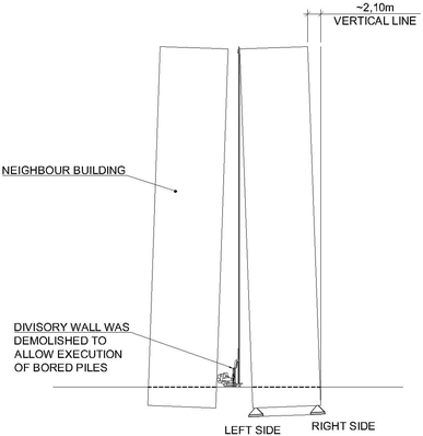
View of the limited space for the equipment
-
No vibrations during foundation works.
-
Minimize dewatering in to avoid settlements.

To protect shallow spread footings bearing in sand, it was not possible to excavate the bored piles (Fig. 15). Then, steel tube was driven with 6 m length at right side and 12 m at left side. The difference in the steel tube length intended to eventually reduce differential settlement. After the steel tubes were installed, the bored piles were excavated using bentonite. As steel tube maximum diameter allowable was 1.50 m, it was decided to use 16 bored piles diameter ranging 1–1.4 m, as it is shown in Fig. 9.

Details of spread footing and bored pile
Figures 10, 11 and 12 show details of Main Beams (VB), Transverse Foots, and Pillars.
Figure 13 shows the system allowing use of hydraulic jacks before and after the plumbing.
During the operation, displacement monitoring were performed, allowing information about the behavior of each jacking step. Although many piles had received more load than predicted by the structural analysis the maximum settlement of the piles was only 0.6 cm.
Differences between predicted pile loads and measured ones could be attributed to ideal behavior of theoretical models applied to describe structure constitutive law of materials and loads during calculations. Other reason to explain differences relies in jacking method, once each pump was connected with a group of hydraulic jacks, to apply different loads by means of jack diameters. Initial steps consisted in calibrating the more efficient arrangement of jacks and sequence of applying loads controlled by time of pumping.
As the loads were neither applied simultaneously nor continuously in all hydraulic jacks, some differential settlements took place, changing pillar loads due to high stiffness of transition and building existing structure. Some jack points had more contribution of loads arousing more difference than theoretical ones.
During initial steps, loads were applied in a careful way and displacements measured allowing us to obtain a state of loads in all hydraulic jacks.
Controlling loads limited to 10–20 % of those measured adjusted ones during jacking and measurement of displacements after each jacking step, the building was plumbed without any fissure.
The building, which was showing a slant of 2.1 m, was plumbed, with 80 cm maximum raise induced. During the reinforcement execution stages, settlements were measured. The settlement evolution during the foundation works and construction of transition beams is shown on Fig. 16.

Settlement of the extreme pillars due to time during the execution of the reinforcement
Figure 17 shows the hydraulic jack system before and after the correction of building inclination. Note the grout wedges that were being placed at each hydraulic jack operation.

The hydraulic jack system before and after the straightening
During operation of jacking, the sandy soil under spread footings was excavated to avoid suction that was turning difficult to arise the building (Fig. 18).

The spread footing excavated
Figure 19 shows the building before and after the conclusion of re-straightening operations.

Photos before and after plumb
Tower B
A structural analysis and an executive design of Tower B were made soon after Tower A. However, as the geometrical characteristics of the two buildings were different, the structure model to plumb Tower B had to be different. One of the main differences is the lack of enough space for installing the large-diameter excavated piles on the sides of the building, or for the construction of the “Vierendeel” beams, as in Tower A. Then, a transition structure constituted of large beams was designed to transfer the loads of pillars of the building to the new foundations as shown in Figs. 20 and 21. New foundations that had to be made inside the building were constituted of root piles of 40 cm in diameter and 55 m in length. These new foundations were designed to withstand the loads of the building. Despite transition structure was different from Tower A, the jacking system should be the same.

Tower B Pillar, root piles, and blocks

Transition Structure
The owners decided to build the new foundations of Tower B soon after the implementation of Tower A foundations in 1999. After performing the work of the root piles, the works on the Tower B were interrupted for the owners to save money to finish the works. Tower B project was restarted only in 2010. During those 11 years, the rate of differential settlements in this building was reduced and became insignificant. The reason for this reduction can be attributed to root pile friction working as a friction “wall” minimizing the effect of the pressure bulb superposition of the neighbor building. As root piles work in a passive way, absolute settlements will continue, despite small values, but differential settlements are insignificant. Figure 22 shows differential settlements already in 2003, as no further measurements were made until the beginning of works. Thus, it was decided to apply another plumb method without constructing transition beams. This method was supposed to be cheaper and faster than the first one.

Settlement due to time of Tower B
The building inclination at the time of plumb is illustrated in Fig. 23. The new method consisted in installing hydraulic jacks in each pillar allowing re-leveling through displacements provided by a jack system, maintaining existing foundations.

Tower A and Tower B (behind the Tower A) in 2010
The execution method in this case can be described as follows: the pillar concrete surface is prepared to allow the construction of reinforced concrete double cantilevers, which were attached to the pillar through pre-stressed steel bars (“DYWIDAG”), as shown in Fig. 24. Auxiliary hydraulic jacks are placed under the cantilevers. The forces applied through hydraulic jacks were obtained by previous calculations. The pillar is then cut and the load is transferred to the auxiliary hydraulic jacks (Fig. 25). The main hydraulic jack is installed, which is activated to replace the auxiliary hydraulic jacks, which were removed. At this stage, the main hydraulic jack assumes the load Figs. 26 and 27.

Execution of double cantilever and pillar was cut after the auxiliary jacks were placed

Detail of auxiliary jacks after pillar was cut and installation of main hydraulic jack

Auxiliary jacks removed and load transferred to main hydraulic jack

Scheme of the execution method
After all the pillars were supported by main hydraulic jacks, the plumb phase starts. This phase consists of applying loads to the system, to reduce the inclination of the building. The loads are kept within narrow limits previously defined by calculations and on observations during plumb operation. Figure 28 shows the action of the hydraulic jack during the building leveling.

Action of the hydraulic jack during the building leveling
So, root piles were not used as foundation, but to minimize differential settlements, as can be seen in Fig. 27.
As during plumb operation in Tower A, evacuation from the buildings was not required, but there was the need to transfer the cables and pipes to an external system to enable their use during the plumb of the building (Fig. 29). After that the original utility systems were reconnected.

Flexible utilities installed to allow operation
After plumb of the building, the main hydraulic jacks were replaced again by the auxiliary jacks and the pillars were reconstituted. The space was filled by reinforced concrete, thus restoring the pillars. The building was leveled after five days of work. Figure 30 shows Tower B before and after plumb.

Initial and final situation
Remarks about settlements after works to plumb towers A and B
Measurements of settlements in buildings in Santos show absolute values of 0.5 at 1.5 cm/year and inclinations varying according to the specific conditions for each building.
New foundation in Tower A bearing in residual soil and jacking work ensure that no more settlements will occur.
Tower B has no new foundation and settlements will continue, but with minimum inclination, reason why it was estimated a 100 years without noting some out of plumb signal.
Owners had no interest in monitoring the building until today. Despite this, some measurements were made, but due to retrofits a lot of settlement pins were out of service; in that way a few data available show values near measurement precision.
Visually building is on plumb. Inhabitants after six years didn´t notice any problem.
Conclusions
The two procedures used to plumb the two buildings proved successful in many aspects, such as:
The utility systems, including lifts, water supply and sewage, remained working during and after the procedure of plumb.
The market price of the apartments increased approximately ten times.
References
Maffei Carlos EM, Gonçalves Heloisa HS, Pimenta Paulo M, Murakami Claudio A (2001) The plumbing of 2.20 inclined tall building. In: Proceedings of the Fifteen International Conference on soil Mechanics and Geotechnical Engineering. Netherlands: Fifteenth International Conference on Soil Mechanics and Geotechnical Engineering, vol 3. AA Balkema Publishers, Avereest, p 1799–1802
Pimenta Paulo M, Maffei Carlos EM, Gonçalves Heloisa HS, Pauletti Ruy M (1998) A programming system non–linear dynamic and static analysis of tall buildings. In: S. Idelsohn, E Oriate, E. Davorkin (eds.) New Trends and Applications. Computation Mechanics
Acknowledgments
We thank the owners and residents of Núncio Malzoni by for the trust and support during construction. We also thank all the colleagues and workers involved in this project, especially MSc Eng. Maria Cecília Guazzelli. This paper presents detailed extension of paper presented on Geochina 2016 International Conference tilled “Two different techniques to the plumbing of two tilted buildings”. Authors would like to emphasize efforts in disseminating innovative techniques—first objective of engineering—as allow events like Geochina 2016 International Conference.
Author information
Authors and Affiliations
Corresponding author
Rights and permissions
Open Access This article is licensed under a Creative Commons Attribution 4.0 International License, which permits use, sharing, adaptation, distribution and reproduction in any medium or format, as long as you give appropriate credit to the original author(s) and the source, provide a link to the Creative Commons licence, and indicate if changes were made.
The images or other third party material in this article are included in the article’s Creative Commons licence, unless indicated otherwise in a credit line to the material. If material is not included in the article’s Creative Commons licence and your intended use is not permitted by statutory regulation or exceeds the permitted use, you will need to obtain permission directly from the copyright holder.
To view a copy of this licence, visit https://creativecommons.org/licenses/by/4.0/.
About this article

Cite this article
Maffei, C.E.M., Gonçalves, H.H.S. Innovative techniques used to plumb two 57 m height concrete buildings leaning 3.8 and 3.1 %. Innov. Infrastruct. Solut. 1, 33 (2016). https://doi.org/10.1007/s41062-016-0032-9
Received:
Accepted:
Published:
DOI: https://doi.org/10.1007/s41062-016-0032-9