
Abstract
During the process of coal mining, there is a violent appearance of mining stress when the initial weighting occurs. To guarantee the safety of the gob-side entry formed automatically by roof-cutting (EFARC) in an inclined coal seam, a study was conducted on the initial weighting mechanism and appearance characteristics through field monitoring and theoretical analysis. The findings reveal that, upon the initial breaking of the main roof in the non-pillar mining stope of an inclined coal seam, the deflection of the thin plate structure exhibits asymmetric distribution, with the maximum position situated in the middle-upper part of the thin plate. As the main roof thin plate reaches its limit interval, the tensile fracture first occurs in the middle-upper part of the coal wall in front and back of the stope. Once broken, the thin plate changes to a simply supported state. The analysis of field data reveals that the mine pressure in the non-pillar stope of EFARC shows an asymmetric weighting phenomenon. The periodic weighting interval at the ends of the working face increases, and the weighting intensity decreases. These results can serve as theoretical support for controlling mine pressure in non-pillar mining through EFARC in inclined coal seams and can serve as a basis for further investigations in this area.
Article highlights
1. The initial pressure mechanism for the EFARC non-pillar mining stope in an inclined coal seam is revealed.
2. The flexure function of the main roof structure is establish by considering the special constraint conditions.
3. The initial failure mechanical mechanism of the main roof structure of EFARC in an inclined coal seam is revealed.
1 Introduction
The gob-side entry formed automatically by roof-cutting (EFARC) is a new, safe, efficient non-pillar mining method in the coal industry. It has been successfully applied in nearly 200 coal mines in China. However, the complex stress and multiple dynamic disasters during the mining of inclined coal seams limit the application of this technology in this geological condition (Zhang et al. 2020a, b). As one of the effective technical means to realize green coal mining, the non-pillar mining method by EFARC has several advantages, including improving coal recovery rate, alleviating continuous tension in production, reducing roadway excavation rate, avoiding stress concentration caused by set coal pillar, realizing Y-type ventilation, and eliminating gas accumulation (He et al. 2018b).
The successful implementation of the new non-pillar mining technology under different geological conditions has led to an increasing number of experts and scholars studying its design parameters (Chen et al. 2019), mine pressure behavior (Wang et al. 2021; Xu et al. 2021), and surrounding rock control of the EFARC (Liu et al. 2020; Wang et al. 2022a, b, c, d), among other aspects (Tang et al. 2022; Liang et al. 2022; He et al. 2022; Wang et al. 2022a, b). Corresponding research results have been obtained. However, most application research focuses on near-horizontal and gentle dip coal seams. When mining inclined coal seams, several problems arise, such as support sliding and complex surrounding rock stress environment, which makes the application of non-pillar mining technology by EFARC in inclined coal seams face challenges (Zhen et al. 2019).
In the process of mining, the first severe dynamic pressure disturbance in the mining space is typically caused by the initial weighting, which leads to the rotation and sinking of the overlying rock in the stope and severe deformation of the surrounding rock of the mining entry (Wang et al. 2020). The pressure relief mechanism and spatiotemporal development law of surrounding rock stress in EFARC were analyzed through theoretical and numerical simulation (Zhang et al. 2020a, b). The evolution mechanism of surrounding rock stress and deformation in the entire life cycle of EFARC was also investigated (Wang et al. Wang et al. 2022a, b, c, d). Moreover, the effects of roof-cutting techniques on the overlying strata’s movement law and the surrounding rock’s deformation features in gob-side entry retaining mines were studied using mechanical analysis (Zhu et al. 2020). A similar three-dimensional simulation experiment of roof precutting was conducted to obtain the roof strata’s caving characteristics and migration law in the strike and dip directions (Hua et al. 2021). However, there is currently no related research on the initial pressure mechanism of EFARC in an inclined coal seam. This paper aims to establish the flexure test function of the main roof structure under the boundary conditions, considering the special constraint conditions of the main roof structure of EFARC in an inclined coal seam. The stress distribution of the main roof structure is obtained by using the relationship between work and energy and the relationship between thin rectangular plate stress and deflection parameters. Analyzing the breaking state of the main roof structure reveals the initial failure mechanical mechanism of the main roof structure of EFARC in an inclined coal seam. Finally, the theoretical analysis is validated using the test site mine pressure monitoring data. The research results provide reasonable surrounding rock control ideas in an inclined coal seam and enriching the non-pillar mining technology application scene by EFARC.
2 The non-pillar mining technology by EFARC
2.1 Technological principles
The non-pillar mining technology developed by EFARC is based on the roof-cutting short arm beam theory. It employs a technical support system that utilizes the constant resistance large deformation anchor cable (CRLDA), directional energy accumulation pre-splitting technology, and temporary support. This system takes advantage of the characteristics of the broken expand gangue during the mining process to achieve entry automatically formatted behind the working face. According to Zhen and Gao (2020), the basic principle of this technology involves three stages:
-
a.
Before mining begins, the CRLDA is used to increases the bearing capacity of the roof strata, allowing it to withstand the stress disturbance that occurs during the pre-splitting blasting and mining process.
-
b.
After completing the roof reinforcement, directional pre-splitting technology making the gob-side entry located in the weak mining-stress area.
-
c.
As the working face advances, the rock mass in the goaf collapses along the cutting line. Based on specific protection measures, the collapsed rock automatically forms one side of the gob-side entry. The technical principle and flow diagram of EFARC is shown in Fig. 1.

The technical principle of the EFARC and schematic diagram of the formation process
2.2 Geological conditions of the test site
The test site Jinfeng Coal Mine is located southeast of Wuzhong City, Ningxia, China. The test face is the 011810 working face of the mine, and the buried depth is 214–328 m, the strike length is 1023 m, the width of the working face is 260 m, the dip angle range of the coal seam is 12°–32°, the average dip angle of the coal seam is 22°, and the average thickness of coal is 3.75 m. The immediate roof is siltstone with a thickness of 7.1 m, the main roof is fine sandstone with a thickness of 6.8 m, the immediate bottom is siltstone with a thickness of 1.3 m, and the main bottom is fine sandstone with a thickness of 5.5 m. The overlying dip angle of the coal seam varies greatly, the maximum dip angle at the open-off cut is 32°, and the dip angle along the strike of the working face gradually changes to 13°. The geological conditions of the test site are shown in Fig. 2.

Schematic diagram of geological conditions of the test site (Part (I) Geographic location of the test site. Part (II) Geological conditions of the test site)
3 Mechanism and characteristics of the initial weighting in non-pillar stope of EFARC in the inclined coal seam
3.1 Establish the mechanical model
The breaking process of the overlying rock in the inclined coal seam stope of EFARC differs significantly from that of horizontal coal seams due to the influence of both mining and tectonic stresses. We established a geological model map to better understand the main roof breaking process of EFARC in inclined coal seams. The map simplifies the overlying rock structure of the stope into three parts: the immediate roof, main roof, and overlying strata while considering the dip angle of the coal seam (α). The rapid accumulation area forms due to the caving rock accumulation in the lower part of the working face, affected by the coal seam inclination. The roof-cutting affected area is where the roof pressure weakens due to the roof-cutting. The geological model is presented in Fig. 3.

Geological model of the non-pillar mining stope of EFARC in the inclined coal seam
The behavior of stope pressure is closely related to the fractured state of the main roof. Typically, when studying the mechanical mechanism of the main roof, it is considered thin plates according to the thin plate theory. In the non-pillar mining technique used by EFARC in inclined coal seams, gangue falls into the goaf and slides or rolls down to the lower part of the working face due to gravity. This creates an accumulation area of gangue with particular supporting strength in the lower part of the goaf. As a result, the main roof experiences a different restraining effect of gangue along the direction of the working face (Wang et al. 2016). To model the main roof mechanics in non-pillar mining by EFARC in an inclined coal seam, the X-axis represents the length of the working face, the Y-axis represents the advancing direction of the working face, and the Z-axis is perpendicular to the main roof. The model is fixed on three sides and simply supported on one side, ignoring the horizontal tectonic stress in the study area. The vertical load consists of overlying strata load P and gangue support Pz. Using this model, the range of the X-axis is from 0 to 2a, and the range of the Y-axis is from 0 to 2b, as shown in Fig. 4(Part I).

Main roof mechanics model of non-pillar stope of EFARC in inclined coal seam (Part (I) The main roof mechanical model. Part (II) The main roof support conditions and the plane stress diagram)
In order to prevent the transmission of stress between the goaf and the roof of EFARC and to improve the stress environment of the entry prior to mining, the roof of one side of the entry will be pre-fractured by roof cutting. The main roof is considered to have one side simple support, with the other three sides being fixed before the initial fracture. Figure 4(part II) illustrates the support conditions of the main roof and the plane stress diagram.
3.2 Analysis of mechanical mechanism of the initial fracture of main roof
According to the established geological and mechanical model in the previous section, the load exerted by the overlying strata on the main roof can be expressed as a linear load function, P(x), which increases along the inclined direction from the end of the working face, as shown in Eq. (1):
where \({\gamma }_{1}\) represents the average bulk density of the overlying strata, \({H}_{1}\) is the thickness of the overlying strata, \(x\) represents the length of the working face (0–2a), and α represents the dip angle.
Based on the above analysis, the mechanical model for the main roof of non-pillar mining by EFARC in the inclined coal seam has the following boundary conditions: three sides are fixed, and one side is simply supported. The fixed side has zero deflection and rotation angle, while the simply supported side has zero deflection and bending moment. The displacement boundary conditions for the model are:
In the formula, \(x\) is the length of the working face (0–2a), \(y\) is the advancing direction of the working face (0–2b), \(\omega\) is the deflection.
The model is solved by the Ritz method, which is a direct variational method based on the minimum potential energy principle. By selecting a trial function to approximate the exact solution of the problem, substitute the trial function into the function of a scientific problem, and then the stationary value of the function is obtained to determine the undetermined parameters in the trial function. thus, obtain the approximate solution of the problem. With this method, the first-order expression of the main roof function, which satisfies the above displacement boundary conditions, is set as \(\omega (x,y) = C_{1} \omega _{1}\), and it can be expressed as:
\({C}_{1}\) is the coefficient of trial function, \(x\) and \(y\) represent the length and advancing direction of the working face respectively and they range from 0 to 2a and 0 to 2b respectively.
After checking, the first-order expression of the function is satisfied with the displacement boundary conditions that above-mentioned. It can be seen that:
The total potential energy of the thin plate can express as the difference between the work done by lateral force and longitudinal force on the plate with the plate’s strain energy, and it can define as:
where I represents the total potential energy of the plate, U is the strain energy of the inclined thin plate, V is the work done by the lateral force on the inclined plate, and W is the work done by the longitudinal force on the inclined thin plate.
-
(1)
According to the formula which shows the bending strain energy of the thin plate:
$$U=\frac{D}{2}{{\int }_{0}^{2b}{\int }_{0}^{2a}\left(\frac{{\partial }^{2}\omega }{\partial {x}^{2}}+\frac{{\partial }^{2}\omega }{\partial {y}^{2}}\right)}^{2}dxdy$$(8)U can be expressed as:
$$U=\frac{D}{2}{{\int }_{0}^{2b}{\int }_{0}^{2a}\left({C}_{1}\frac{\pi }{a}{sin}\frac{\pi y}{2b}({sin}\frac{\pi x}{a}+\frac{\pi }{2a}x{cos}\frac{\pi x}{a})+{C}_{1}\frac{{\pi }^{2}}{2{b}^{2}}x{{sin}}^{2}\frac{\pi x}{2a}{cos}\frac{\pi y}{b}\right)}^{2}dxdy$$(9)\(D\) is the bending stiffness of the thin plate, \(D=\frac{{E}_{2}{{H}_{2}}^{3}}{12(1-{{\mu }_{2}}^{2})}\)where, \({E}_{2}\),\({H}_{2}\),\({\mu }_{2}\)respectively, is the elastic modulus, thickness, and Poisson’s ratio of the main roof.
-
(2)
The work done by the lateral force on the inclined plate.
The lateral force is composed of the gravity stress of the overlying strata perpendicular to the plate and the gangue supporting force \(Pz\), and its work on the inclined thin plate express as the following formula:
$$V=\iint {P}_{1}\omega dxdy-\iint {P}_{z}\omega dxdy$$(10),
In which,\(\iint {P}_{1}\omega dxdy={\int }_{0}^{2b}dy{\int }_{0}^{2a}(\gamma 1H1+\gamma 1(2a-x\left){sin}\alpha \right){cos}\alpha \omega dx\)
The work done by the gangue supporting force on the main roof can be expressed as:
$$\iint {P}_{z}\omega dxdy={\int }_{0}^{2b}dy{\int }_{a-{L}_{2}}^{a+{L}_{2}}\frac{q}{2}\omega dx+{\int }_{0}^{2b}dy{\int }_{0}^{2a}(-\frac{q}{2})\omega dx+{\sum }_{n=1}^{\infty }{\int }_{0}^{2b}dy{\int }_{a-{L}_{2}}^{a+{L}_{2}}\left[\left(\frac{2q{{sin}}^{2}(\frac{n\pi }{2})}{n\pi }\right){sin}\frac{n\pi x}{{L}_{2}}\right]\omega dx+{\sum }_{n=1}^{\infty }{\int }_{0}^{2b}dy{\int }_{a-{L}_{2}}^{a+{L}_{2}}\left[\left(-\frac{2q{{sin}}^{2}(\frac{n\pi }{2})}{n\pi }\right){sin}\frac{n\pi x}{a}\right]\omega dx$$(11)\({L}_{2}=a-{L}_{1}\), \({L}_{1}=\frac{K({h}_{3}{)}^{2}}{{h}_{4}}\sqrt{\frac{2{R}_{t}({E}_{3}{{h}_{3}}^{3}+{E}_{2}{{h}_{2}}^{3}+{E}_{1}{{h}_{1}}^{3})}{{E}_{3}{{h}_{3}}^{3}({\gamma }_{3}{h}_{3}+{\gamma }_{2}{h}_{2}+{\gamma }_{1}{h}_{1}){cos}\alpha }}\), \(q\) is the supporting force of gangue, \(K\) is the expansion coefficient of immediate roof, \({R}_{t}\) is the tensile strength limit, \({h}_{i}\) is the thickness of each layer, \({\gamma }_{i}\) is the volume force of each layer, \({E}_{i}\) is the elastic modulus of each layer.
-
(3)
The work done by the longitudinal force on the inclined plate.
According to the thin plate theory, the load done by the longitudinal force can be expressed as follows:
$$W=\frac{1}{2}\iint {N}_{x}\left(\frac{{\partial }^{2}\omega }{\partial {x}^{2}}\right)+{N}_{y}\left(\frac{{\partial }^{2}\omega }{\partial {y}^{2}}\right)+2{N}_{xy}\left(\frac{\partial \omega }{\partial x}\frac{\partial \omega }{\partial y}\right)dxdy$$(12)Among them, \({N}_{x}\),\({N}_{y}\),\({N}_{xy}\) are the internal force caused by the longitudinal load on a differential block in the middle surface of the plate, and then only consider the influence of self-weight stress, \({N}_{y}={N}_{xy}=0\), \({N}_{x}dx={\tau }_{x}\), \({N}_{x}={\tau }_{x}x+{{\tau }_{x}}_{0}\), \({\tau }_{x}\) is the longitudinal load in the x-direction. From the mechanical analysis, it can be seen that, \({\tau }_{x}={P}_{2}+{G}_{2}\),\({P}_{2}=\left[{\gamma }_{1}{H}_{1}+{\gamma }_{1}(2a-x){sin}\alpha \right]{sin}\alpha\),\({G}_{2}={\gamma }_{2}{H}_{2}{sin}\alpha\),Finally, we can know:
$$W=\frac{1}{2}\iint \left[{\gamma }_{1}{H}_{1}+{\gamma }_{1}(2a-x){sin}\alpha +{\gamma }_{2}{H}_{2}\right]{sin}\alpha x+\left[{\gamma }_{1}{H}_{1}+{\gamma }_{1}(2a-x){sin}\alpha +{\gamma }_{2}{H}_{2}\right]{sin}\alpha \times \left[{C}_{1}\frac{\pi }{a}{sin}\frac{\pi y}{2b}({sin}\frac{\pi x}{a}+\frac{\pi }{2a}x{cos}\frac{\pi x}{a})\right]dxdy$$(13)Table 1 Physico-mechanical parameters of adjoining rocks Taking \(U,V\) and \(W\) into Formula (6), according to the principle of minimum potential energy, substitute relevant parameters where the length of the working face is 260 m, the advancing size is 40 m, and the inclination angle of the working face is 32°. The mining height is 3.8 m, and the mechanical parameters of stope strata are shown in Table 1. We can know that \({C}_{1}=4.69\times 1{0}^{\text{-4}}\), so that the deflection distribution of inclined thin plate under non-uniformly distributed load can be obtained, as shown in Fig. 5.
Fig. 5 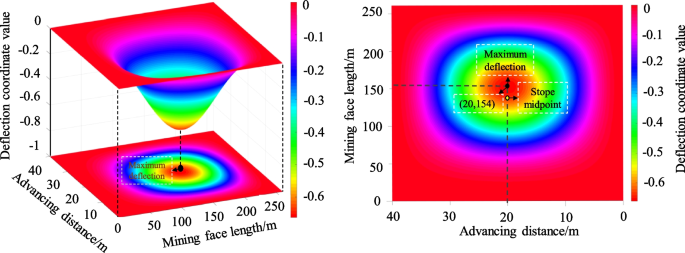
Deflection distribution of the inclined thin plate under non-uniformly distributed load
The three-dimensional distribution map of the main roof deflection of the non-pillar stope in the inclined coal seam of EFRAC reveals that the point of maximum deflection is not located at the geometric center of the stope. The deflection coordinate values of the extreme point are x = 154 in the strike direction and y = 20 in the inclined direction, with a maximum bending subsidence value of − 0.74 m. This extreme point is situated at the midpoint of the advancing direction and in the upper position in the inclined direction.

3.3 Stress distribution of main roof thin plate
The internal force expression of the inclined thin plate structure can be derived by using the elastic mechanic’s deflection function and substituting the deflection function obtained from the inclined thin plate into the functional relationship between the stress and deflection parameters of the narrow rectangular plate.
Substituting the corresponding function into the formula (14), we can obtain:
where \(\text{x}\in \left(\text{0,2}\text{a}\right),\text{y}\in \left(\text{0,2}\text{b}\right),\text{z}=0.5{\text{h}}^{2}\)
By substituting the parameters of the stope into the formula (15), obtain the internal stress distribution map of the inclined thin plate before the initial fracture when the working face is advanced for 40 m, as shown in Fig. 6.

Internal stress distribution map of inclined thin plate before primary fracture: a \({\sigma }_{x}\); b\({\sigma }_{y}\) ; c \({\tau }_{xy}\)
According to the three-dimensional distribution of the internal force of the main roof, the maximum compressive stress \({\sigma }_{x}\) occurs at x = 154 m, y = 20 m, and the value is 71.47 MPa. The maximum tensile stress point is located at the upper midpoint of the two long edges of the thin plate, and the value is 69.72 MPa. The position of the maximum compressive stress \({\sigma }_{y }\)is the same as \({\sigma }_{x}\), the maximum compressive stress value is − 21.56 MPa, and the maximum tensile stress is + 20.3 MPa, the shear stress in the inclined thin plate is diagonally asymmetric distribution. The maximum positive shear stress and negative shear stress appear in the upper part of the inclination direction, and the coordinates are x = 254 m, y = 29 m and x = 256 m, y = 10 m, the values are 52.3 MPa, and 51.7 MPa, respectively.
3.4 Analysis of the breaking state of inclined main roof plate in the non-pillar stope of EFARC
Taking the internal force expression into the principal stress formula, we can know the principal stress expression of any point on the main roof inclined thin plate:
From the analysis, we can know the expression of the maximum principal stress at any point on the inclined thin plate:
The rock mass has the characteristic that the compressive strength is generally more significant than the tensile strength, so when the tensile stress of the principal stress is greater than the tensile strength of the main roof rock mass, the tensile fracture of the rock mass occurs, the critical fracture of the main roof and the fracture criterion when the fracture occurs, express as the following formula:
Let \(G\left(x,y\right)={\sigma }_{1}/{\sigma }_{T}\), when the value of the function \(G\left(x,y\right)\) is greater than 1, the main roof is broken in the form of tension at the coordinates (x, y).
According to the geological conditions and rock mechanics parameters of the 011810 working face in the Jinfeng Coal Mine, the contour map of the upper surface of the basic roof sheet is made by using MATLAB software, as shown in Fig. 7.

Isoline map of plate surface on main roof thin plate
From the picture, when the main roof reaches the limit step, in the middle-upper position of the coal wall in front and rear of the working face, the value of \(G\left(x,y\right)\) is greater than 1. Therefore, the tensile fracture first occurs in this position, the crack development range is between 105 and 200 m from the lower of the working face along the dip direction, and the thin plate, after breaking, changes into a simply supported state. That is, the first weighting position of the non-pillar mining stope by EFARC is in the upper part of the working face.
In conclusion, when the main roof of the non-pillar mining stope in the inclined coal seam is first broken, the deflection of the thin plate structure exhibits asymmetric distribution. The maximum deflection of the main roof does not occur at the geometric midpoint of the stope, as in the horizontal coal seam. Instead, it offsets upward in the inclined direction, with the extreme value coordinate being (154,20). Similarly, the maximum stress and the first fracture position in the main roof are also located in the middle-upper part of the coal wall in front and rear of the working face, consistent with the deflection distribution. The analysis indicates that the constraint conditions of the main roof and the arrangement pattern of the overburden structure in the inclined stope are different from those in the horizontal coal seam due to the influence of dip angle and roof cutting, resulting in specific characteristics of stress distribution.
4 Stope pressure data monitoring
4.1 Monitoring content and station layout
Monitoring the pressure changes within a stope is crucial to understanding the interaction between the support and overlying strata. By monitoring the support’s stress status, the behavior of the pressure in the stope can be analyzed to understand the movement of the overlying strata better. There are 156 supports in the 011810 working face of Jinfeng Coal Mine, including three end supports, one transition support, and 152 middle supports. The central distance between the supports is 1.75 m. When examining the support pressure in the working face, we thoroughly assessed all 156 hydraulic supports across the entire working face. To comprehensively analyze the support pressure, we initially divided the working face into distinct vital areas: upper, middle-upper, middle, and lower. This division was based on the outcomes of theoretical analysis. We compared and analyzed the pressure data from 10 hydraulic supports in each region within these crucial areas. We specifically selected representative supports that effectively demonstrated the pressure characteristics within the study area. Monitoring data for resistance at the end of each cycle of supports in the upper (NO.5), middle-upper (NO.75), middle (NO.95), and lower part (NO.150) of the working face were selected to analyze the pressure performance of the working face. The number of the selected supports is shown in Table 2. Figure 8 shows the location of the pressure monitoring equipment.

Layout diagram of mine pressure monitoring station
4.2 Analysis of monitoring results
To facilitate the study of the relationship between the hydraulic support load and the weighting of the working face, the criterion for judging the weighting of the working face was defined as: when the support load was higher than the sum of the average load and the quadratic mean deviation, we judge that the working face had roof weighting (He et al. 2018a). The load distribution curve of the support, the average load, and the pressure judgment reference line are shown in Fig. 9.

Load distribution in the working face
The load distribution map of the NO.5 support in the lower part of the working face indicates no significant pressure phenomenon in that area. Using the weighting criterion, NO.5 support has an initial weighting distance of 39 m, with a maximum load of 28.32 MPa, a periodic weighting distance of 21 m, and a maximum load of 28.23 MPa during periodic weighting. Indicates that due to roof-cutting and the coal seam’s inclination, the rock collapse in this area is relatively sufficient and fills the goaf quickly, resulting in limited space for the roof rotation and subsidence, which to some extent restrains the main roof’s intensity of rotary sinking and weakens the dynamic pressure’s weighting strength.
After analyzing the load distribution map of the NO.75 support in the middle of the working face, it is evident that this support experiences initial and periodic weighting phenomena during the advancement of the working face, and the load increases significantly during pressure periods. The initial weighting distance of the NO.75 support is 31 m, with a maximum load of 45.21 MPa. The periodic weighting distance is about 14 m, and the peak load of the periodic weighting is 44.86 MPa.
From the load distribution map of the NO.95 support in the middle-upper part of the working face, we can get that the pressure phenomenon is evident in this aera, the initial weighting distance is 34 m, with a maximum load of 48.39 MPa. The periodic weighting distance is 15 m, and the peak load value is 46.32 MPa.
From the analysis of the load distribution map of the NO.150 support in the upper part of the working face, it can be seen that the support load does not show an apparent increase. The initial pressure distance of the support is 35 m, the peak load is 37.32 MPa, the periodic weighting distance is 18 m, and the peak load of the support is 37.29 MPa.
4.3 Analysis of the strata behavior characteristics in the stope
Based on the weighting judgment method mentioned above, we can get the peak load distribution map of initial weighting along the working face, as shown in Fig. 10. The map shows that the weighting distribution in the inclined coal seam by EFARC is asymmetric, with the weighting strength following the order of middle-upper > middle > upper > lower parts of the working face. Due to the lower part being close to the roof cutting area, the weighting phenomenon is not apparent. The length of the lower load area of the lower part is 46 m, and the upper part is 38 m.

Load distribution of first weighting in working face
The data of the initial weighting of the upper, middle, middle-upper, and lower part supports during the mining advance are counted, and the results are shown in Table 3.
The statistical data presented in Table 3 reveals that the initial weighting in the middle-upper of the working face is conspicuous, with the largest value found in the middle-upper part, which is 3.18 MPa (about 7%) higher than that in the middle. Compared with the upper part, the initial weighting peak value in the lower part of the working face decreased by 5.37 MPa (about 14%), with an increased initial weighting distance. This is mainly because the roof strata in the upper part are still in a longwall beam state, and the gangues in goaf slide down to the lower part because of the inclination of the coal seam, leading to a larger rotary subsidence space of the main roof and thus increased pressure intensity. On the other side of the working face, the roof is fully supported by caving gangue, and the initial weighting distance in the lower part increases due to roof cutting and gangue sliding. This shows that roof cutting can reduce the pressure strength and optimize the stress environment of the stope.
Sort out load pressure data of the selected support and choose the monitoring data within the mining advancing distance of 120 m. Get the distribution map of the initial and periodic weighting, as shown in Fig. 11.

Distribution of support weighting in working face
Based on the analysis of Fig. 11, it can be observed that there are significant variations in weighting strength and periodic weighting distances on both sides of the working face when compared to the central area. The upper part of the working face exhibits higher weighting strength, with a peak pressure of 48.39 MPa and a smaller weighting distance. The initial weighting distance of the working face at the lower part is 39 m, followed by the upper and middle-upper parts at 35 m and 33 m, respectively. Additionally, the periodic weighting distance is the largest in the lower region. The analysis indicates that the initial collapse of the overlying layers in the non-pillar mining area of an inclined coal seam is influenced by the dip angle of the coal seam. After the collapse, the immediate roof in the upper-middle section slides and rolls toward the working face, reducing its support on the main roof in that area. The collapsed higher-level layers must be filled in the goaf to compensate for this lack of support. Consequently, the collapse zone in the upper-middle part of the mining area is relatively high, leading to a more severe weighing phenomenon. In the lower part of the working face, the goaf is densely filled with waste rock due to the combined effects of roof cutting and the dip angle of the coal seam. This waste rock provides significant support to the main roof. When the overlying layers initially fracture, the height of the caving zone is low, and the intensity and step distance of the weighing are relatively small.
Judging from the weighting phenomenon, the fracture sequence of overlying strata and the distribution of the falling zone in the non-pillar mining stope by EFARC in the inclined coal seam exhibit asymmetric characteristics. These findings are consistent with the mechanical analysis of the overlying strata first breaking in the stope.
5 Discussion
Based on the mechanical analysis presented earlier, it can be concluded that the constraint condition of the main roof thin plate in the non-pillar mining stope by EFARC in an inclined coal seam is fixed on three sides and simply supported on the other due to the dip angle and roof cutting. As the hanging roof area of the stope increases with coal seam mining, tensile and shear stresses first appear in the middle-upper part of the two long sides of the thin plate, followed by the short upper side and the central region. The main roof is prone to failure in positions with high tensile stress due to the compressive capacity of the rock being much greater than the tensile capacity. The pressure distribution state of the inclined thin plate suggests that the main roof first breaks in the middle-upper part of the two long sides (breakdown area I), followed by tensile failure on the short side and the maximum flexure position of the thin plate (breakdown area II and III). The fracture then extends and penetrates continuously in the middle and on two long sides, forming the shape of an O-X fracture. However, the lower part weighting distance is longer than the upper due to the different restraints of gangue on the two ends of the thin plate. This results in the lower opening being larger than the upper opening in the formed O-X fracture. The on-site mine pressure data confirm this phenomenon. Figure 12 shows the final fracture form of the main roof in the non-pillar mining stope by EFARC in an inclined coal seam.

Main roof of inclined thin plate “o-x” failure form
6 Conclusion
Based on the analysis of the main roof fracture and mine pressure behavior characteristics of the non-pillar mining stope of EFARC in the inclined coal seam, the study draws the following conclusions:
-
1.
The main roof fracture occurs asymmetrically with the top position in the middle-upper part of the stope, and the thin plate changes to a simply supported state after breaking.
-
2.
The initial weighting intensity and space-time state of the non-pillar stope show asymmetric characteristics.
-
3.
The tensile fracture is the primary failure mode, and the main roof eventually forms an o-x fracture form. The knowledge of the initial fracture position of the main roof and weighting characteristics of the non-pillar stope in the inclined coal seam can provide theoretical guidance for production safety.
The results suggest that preventive forced caving can be carried out in critical areas of mining pressure to weaken the influence of stress on surrounding rock stability. Furthermore, defining the critical monitoring area of stope support can enhance the scientific management level of stope mining pressure. These research findings provide theoretical support for mine pressure control and surrounding rock stability control during non-pillar mining by EFARC in the inclined coal seam.
Availability of data and materials
The data used to support the findings of this research are included within the paper. More information can be requested from the corresponding author.
References
Chen SY, Zhao F, Wang HJ, Wang HJ, Yuan GX, Guo ZB, Yang J (2019) Determination of key parameters of gob-side entry retaining by cutting roof and its application to a deep mine. Rock Soil Mech 40(01):332–343+350
He MC, Ma ZM, Guo ZB, Chen SY (2018a) Key parameters of the gob-side entry retaining formed by roof cutting and pressure release in deep medium-thickness coal seams. J China Univ Min Technol 47(3):468–477
He MC, Wang YJ, Yang J, Gao YB, Gao Q, Wang SB (2018b) Zonal characteristics and its influence factors of working face pressure using roof cutting and pressure-relief mining method with no pillar and roadway formed automatically. J China Univ Min Technol 47(6):1157–1165
He MC, Sui QR, Li MN, Wang ZJ, Tao ZG (2022) Compensation excavation Method Control for large deformation Disaster of Mountain Soft Rock tunnel. Int J Min Sci Technol 5:951–963
Hua XZ, Chang GF, Liu X, Sun BJ, Yang S, Wang EQ, Li C (2021) Three-dimensional physical simulation and control technology of roof movement characteristics in non-pillar gob-side entry retaining by roof cutting. Shock Vib. Volume 2021, Article ID 7491414
Liang X, Tang SB, Tang CA, Hu LH, Chen F (2022) Influence of water on the mechanical properties and failure behaviors of sandstone under triaxial compression. Rock Mech Rock Eng. https://doi.org/10.1007/s00603-022-03121-1
Liu X, Hua XZ, Yang P, Huang Z (2020) A study of the mechanical structure of the direct roof during the whole process of non-pillar gob-side entry retaining by roof cutting. Energy Explor Exploit 38(5):1706–1724
Tang SB, Li JM, Ding S, Zhang LT (2022) The influence of water–stress loading sequences on the creep behavior of granite. Bull Eng Geol Environ 81:482. https://doi.org/10.1007/s10064-022-02987-3
Wang HW, Wu YP, Xie PS (2016) The quantitative filling characteristics of the waste rock and roof movement mechanism in the steeply inclined working face. J China Univ Min Technol 45(05):886–891
Wang YJ, He MC, Yang J (2020) Case study on pressure-relief mining technology without advance tunneling and coal pillars in longwall mining. Tunn Undergr Sp Tech 97, Article ID 103236.
Wang J, Li WF, Zhu DY, Gong WL, Su Y (2021) Novel application of the roof-cutting-type gob-side entry retaining in Coal Mine. Math Probl Eng. Article ID 1625282
Wang Q, Xu S, Xin ZX, He MC, Wei HY, Jiang B (2022a) Mechanical properties and field application of constant resistance energy-absorbing anchor cable. Tunn Undergr Space Technol 125:104526
Wang H, Li H, Tang L, Ren X, Meng Q, Zhu C (2022b) Fracture of two three-dimensional parallel internal cracks in brittle solid under ultrasonic fracturing. J Rock Mech Geotech Eng 14(3):757–769
Wang Y, Zhu C, He MC, Wang X, Le HL (2022c) Macro-meso dynamic fracture behaviors of Xinjiang marble exposed to freeze thaw and frequent impact disturbance loads: a lab-scale testing. Geomech Geophys Geo Energy Geo Resour 8(5):154
Wang YJ, Wang Q, Tian XC, Wang HS, Yang J, He MC (2022d) Stress and deformation evolution characteristics of gob-side entry retained by roof cutting and pressure relief. Tunn Undergr Sp Tech Vol.123, Article ID 104419.
Xu XD, He MC, Gao YB (2021) Study on mining pressure law and pressure relief control under influence of key layer. Min Metall Explor 38:1985–1996
Zhang Y, Xu HC, Song P, Sun XM, He MC, Guo ZB (2020a) Stress evolution law of surrounding rock with gob-side entry retaining by roof cutting and pressure release in composite roof. Adv Mater Sci Eng 2020, Article ID 1961680
Zhang XY, Ronald YSP, Gao YB, Liu CK, Zhang C, Yang J, He MC (2020b) Field experiment on directional roof presplitting for pressure relief of retained roadways. Int J Rock Mech Min Sci Article ID 104436
Zhen EZ, Gao YB (2020) Application of roof-cutting and pressure-release entry retaining in inclined coal seams: a case study. Geotech Geol Eng 38:2559–2572
Zhen EZ, Gao YY, Wang YY, Wang SM (2019) Comparative Study on Two Types of Non-pillar Mining Techniques by Roof Cutting and by Filling Artificial Materials. Advances in Civil Engineering. Volume 2019, Article ID 5267240
Zhu DY, Wang J, Gong WL, Sun Z (2020) Model test and numerical study on surrounding rock deformation and overburden strata movement law of gob-side entry retaining via roof cutting. Minerals 10:458
Funding
This work is supported by the, the Natural Science Foundation of Beijing Municipality (No. 8232056), the Natural Science Research Project of Anhui Universities (KJ2020A0317), the Natural Science Research Project of Huangshan University (2020xkjq017), and the Open Project Program Foundation of Engineering Research Center of underground mine construction, Ministry of Education (Anhui University of Science and Technology) (JYBGCZX2021106), which are gratefully acknowledged.
Author information
Authors and Affiliations
Contributions
EZ wrote the main manuscript text. SD and JH conducted an analysis of the field data. XZ and YT prepared the figures in the manuscript. YW and MW put forward the innovative points of the article and gave the support of the funding. All authors reviewed the manuscript.
Corresponding authors
Ethics declarations
Ethics approval and consent to participate
Ethics approval was not required for this research.
Consent to publish
All authors consent to the publication of this paper.
Competing interests
The authors declare no competing interests.
Additional information
Publisher’s Note
Springer Nature remains neutral with regard to jurisdictional claims in published maps and institutional affiliations.
Rights and permissions
Open Access This article is licensed under a Creative Commons Attribution 4.0 International License, which permits use, sharing, adaptation, distribution and reproduction in any medium or format, as long as you give appropriate credit to the original author(s) and the source, provide a link to the Creative Commons licence, and indicate if changes were made. The images or other third party material in this article are included in the article's Creative Commons licence, unless indicated otherwise in a credit line to the material. If material is not included in the article's Creative Commons licence and your intended use is not permitted by statutory regulation or exceeds the permitted use, you will need to obtain permission directly from the copyright holder. To view a copy of this licence, visit http://creativecommons.org/licenses/by/4.0/.
About this article

Cite this article
Zhen, E., Dong, S., Huang, J. et al. Analysis of the EFARC non-pillar mining stope: roof failure and overlying pressure in inclined coal seams. Geomech. Geophys. Geo-energ. Geo-resour. 9, 151 (2023). https://doi.org/10.1007/s40948-023-00691-4
Received:
Accepted:
Published:
DOI: https://doi.org/10.1007/s40948-023-00691-4