
Abstract
To study the heights of the caved zone and water-conducting fracture zone in backfill mining, the failure mechanism of strata during backfill mining was analyzed, and a method for determining the heights of the two zones was proposed based on key strata theory. The movement and failure regularity of the strata above the backfilling panel were revealed through numerical simulation. Considering the geologic conditions of the CT101 backfilling panel, the height of the fracture zone was determined using the proposed method along with empirical calculation, numerical simulation, and borehole detection. The results of the new calculation method were similar to in situ measurements. The traditional empirical formula, which is based on the equivalent mining height model, resulted in large errors during calculation. The findings indicate the reliability of the new method and demonstrate its significance for creating reference data for related studies.
1 Introduction
With the continuous mining of China’s coal resources, the proportion of coal under infrastructure, water bodies, and railways has grown. Thus, it is imperative to free the resources and prolong the service lives of important mining areas. Among the different types of coal mining, mining underwater bodies poses the greatest threat to safety. The accurate estimation of the heights of the caved zone and water-conducting fracture zone plays a decisive role in underwater mining (Guo et al. 2013; Wu et al. 2013; Kang et al. 2009; Xuan et al. 2008). Numerous studies have calculated the heights of these two zones, and empirical formulas for estimating the heights for overlying strata with different properties have been derived via the linear regression of measured data (Administration of Coal Industry 2000). New methods for calculating height have been proposed based on key strata theory (Xu et al. 2012; Wang et al. 2013) and verified using in situ measurements, and the calculation results were closer to the measured data.
Under the same geological conditions, the goaf space can be reduced by filling it with foreign materials (i.e., backfilling) (Nagaratnam et al. 2015; Straskraba et al. 1994; Sun et al. 2015; Ding et al. 2006; Liu and Zhao 2014). In backfill mining, the failure height of the overburden is drastically decreased compared to that in the caving method. Thus, backfill mining is a valuable technique for freeing underwater coal resources. Researchers at the China University of Mining and Technology have developed and demonstrated coal-mining techniques and equipment for solid backfill mining (Zhang et al. 2017; An et al. 2016; Huang et al. 2012; Zhang et al. 2016; Liu et al. 2014; Li et al. 2014). However, calculations of the heights of the caved and water-conducting fracture zones during backfill mining are limited. In this study, a new method based on key strata theory was developed for calculating the heights of the two zones via the analysis of the failure regularity of the overlying strata, and the new method was verified by comparison to borehole measurements.
2 Overburden failure mechanism in solid backfill mining
Empty space exists between the backfilling body and the immediate roof during solid backfill mining. As the mining area increases, the immediate roof collapses and fills the goaf, forming the caving zone. If the thickness of the immediate roof is relatively large, the empty space can be filled after the roof collapses and is compacted; in this case, the key strata only bend and sink instead of breaking. The caved zone and water-conducting fracture zone lie beneath the key strata, as shown in Fig. 1a. When the thickness of the immediate roof is small, a free space exists in the goaf after the collapse of the immediate roof. As the mining area increases, the key strata break when the height of the free space under the key layer becomes sufficiently large. If a hinge structure exists after the failure, the key strata and the affected layer will become the water-conducting fracture zone, while the layers beneath it are the caving zone (Fig. 1b). If no hinge structure is formed, the key strata and the affected layer will be caved, thereby requiring the determination of higher key strata to locate the fracture zone. Because of the free space in the goaf, the failure height of the overburden can be dramatically reduced by using the backfilling method compared to the caving method. Under normal circumstances, the ranges of the caved zone and fracture zone can be determined based on the estimation of a few key strata.

Failure patterns of the overburden during backfill mining
3 New calculation method for the heights of the caved and fracture zones
Based on key strata theory, a method for the determination of the heights of the caved and fracture zones is proposed according to the failure mechanism of the overburden during backfill mining. The steps of the proposed method are as follows:
- (1)
Determine the key strata above the stope, as shown in Fig. 2.
Fig. 2 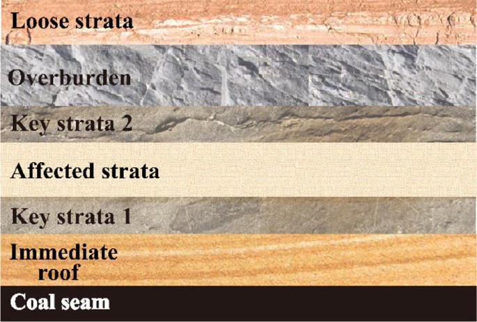
Diagram of the locations of key strata
- (2)
Analyze the free space beneath key strata 1 after mining and backfilling. To simplify the calculation, the height change of the coal pillars and the influence of strata failure are not considered. The backfilled ratio Ff is determined by dividing the backfilling height (Hf) by the height of the goaf (Hc) (Yu et al. 2012):
$$F_{f} = \frac{{H_{f} }}{{H_{c} }} \times 100\%$$(1)The height of the free space Hn can be expressed as
$$H_{n} = \left( {1 - F_{f} } \right)H_{c}$$(2)The compaction degree of the backfilling body (S1) is calculated as (Yu et al. 2011)
$$S_{ 1} = \frac{{e_{0} - e}}{1 + e}H_{f}$$(3)where e is the void ratio after compaction, and e0 is the initial void ratio.
The amount of elastoplastic compression generated by the gravity-driven transfer from the overburden to the backfilling body (S2) can be obtained as follows (Wang et al. 1995):
$$S_{2} = \frac{T}{{E_{m} }}\left\{ {\frac{{1.5\left[ {\left( {1 - K} \right)bp - \sigma_{ct} r_{p} + 2qr_{p} } \right]}}{{a - 2r_{p} }} - \frac{1}{2}\sigma_{ct} } \right\}$$(4)where Em is the elastoplastic modulus; T is the thickness of the coal seam (m); K is the caving coefficient; H is the burial depth (m); q is the concentrated load on key strata; b is the distance between the midpoints of two coal pillars (m); a is the width of the coal pillar (m); rp is the maximum width of the softening zone of the coal pillar in the ultimate state (m); and σct is the ultimate compressive strength of the coal pillar. The elastoplastic modulus Em is given by \(K_{m} \sqrt {sE}\), where Km is the dynamic modulus, E is the initial modulus of the backfilling body (GPa), and s is the characteristic parameter of the backfilling body. For a compacted backfilling body, s = 3 when the rock mass rating (RMR) is 23; for waste rock with small granularity, s = 10−7 when RMR = 3.
From the preceding analysis, the maximum height of free space beneath key strata 1 (S) can be obtained by
$$S = H_{n} + S_{1} + S_{2}$$(5)The existence of free space under key strata 1 can be determined by whether the following equation holds true:
$$H\left( {K^{'} - 1} \right) \ge S $$(6)where H is the thickness of the immediate roof, and K’ is the residual coefficient of bulk increase, which ranges from 1.1 to 1.15. If Eq. (6) holds true, there is no free space under key strata 1 after the collapse of the immediate roof; in this case, the height of the water-conducting fracture zone is approximately equal to the height to which the goaf needs to be filled with broken rock. Equation (7) is as follows:
$$H_{li} = \frac{S}{{K^{'} - 1}}$$(7)Considering the high degree of compaction resulting from the high abutment pressure on the broken rock, K′ = 1.1.
- (3)
If Eq. (6) does not hold true, free space exists under key strata 1. The size of the panel is then considered to determine whether key strata 1 will break (Wang et al. 2013):
$${{a}} - 2H\cot \alpha \ge H_{1} \left( {{{2R_{t} } \mathord{\left/ {\vphantom {{2R_{t} } q}} \right. \kern-0pt} q}} \right)^{{{1 \mathord{\left/ {\vphantom {1 2}} \right. \kern-0pt} 2}}}$$(8)where l is the panel width; α is the breaking angle of the overburden; H1 is the thickness of the key strata; Rt is the tensile strength of the key strata; and q is the load of the key strata.
If Eq. (7) holds true, key strata 1 will break under the influence of mining. If Eq. (7) is not true, the key strata will not be affected.
- (4)
If key strata 1 is determined to break, the three-hinged arch principle (Qian et al. 1994a, b) is applied to determine whether a caved zone or water-conducting fracture zone will be formed (Wang et al. 2013). The condition in which no sliding of fractured rocks occurs is given by
$${{H_{1} } \mathord{\left/ {\vphantom {{H_{1} } L}} \right. \kern-0pt} L} \le {1 \mathord{\left/ {\vphantom {1 {2\tan \varphi }}} \right. \kern-0pt} {2\tan \varphi }}$$(9)where φ is the friction angle between the rocks. The condition in which the fractured rocks experience no deformation instability is described by
$${{\sigma_{p} } \mathord{\left/ {\vphantom {{\sigma_{p} } {\sigma_{c} }}} \right. \kern-0pt} {\sigma_{c} }} \le k$$(10)where σc is the compressive strength of the rock (MPa); k is the empirical coefficient; and σp is the squeezing force of the fractured rocks (MPa), which is given by
$$\sigma_{p} = \frac{{2qi^{2} }}{{\left( {1 - i\sin \beta } \right)^{2} }}$$(11)where β is the sinking angle of the fractured rock, which depends on the space height S and fracture interval L, and i = L/H1.
If Eqs. (9) and (10) hold true for the fractured rocks, the broken key strata 1 will be a fracture zone; otherwise, it will be caved zone.
- (5)
If key strata 1 becomes a caved zone without other key strata above, there will be no water-conducting fracture zone. Otherwise, the aforementioned steps should be repeated to determine whether key strata 2 will break and then determine what type of zone is formed.
In this new method for determining the heights of the caved and fracture zones during backfill mining, the height of free space is the decisive factor in determining the height of broken overburden and the fracture form. To control the deformation and destruction of key strata, the heights of the caved zone and water-conducting fracture zone should be reduced by increasing the compaction of the backfilling body and the backfilled ratio.

4 Engineering verification
4.1 Panel situation
The No. 10 coal seam is the primary mining layer in the Wugou colliery of the Wanbei Coal-Electricity Group. Panel CT101 is located in the South mining area, which is the first backfilling panel. The inclination angle of the panel varies from 2° to 10°, with an average angle of 6°. The average thickness of the coal seam is 3.5 m. The panel width is 100 m, and the length is approximately 587 m along the strike. The position of panel CT101 is shown in Fig. 3.

Position of the CT101 working face
The thickness of the bedrock is approximately 40 m, and the thickness of loose strata is approximately 267 m. The No. 10 coal seam is affected by the water-bearing stratum under the loose strata. To avoid damage to the water-bearing stratum and prevent overburden failure induced by mining, backfill mining was adopted with a backfilled ratio of 85%. Table 1 lists the rock parameters and key strata locations in the overlying strata. The calculation method for key strata referred to Xu et al. (2000).
4.2 Height analysis of the caved and fracture zones
Considering the geological conditions of the CT101 backfilling panel in the Wugou colliery, the heights of the two zones were analyzed using the new method along with empirical calculation, numerical simulation, and by monitoring the quantity of flush fluid circulation loss (borehole detection).
4.2.1 New method for calculating the heights of the caved and fracture zones
The 8.71-m-thick mudstone (No. 7) was determined as the main key strata, and no subkey strata were identified. The initial void ratio of the backfilling body e0 was 0.6, and the void ratio after compaction e was 0.5. Thus, the height of free space Hn was calculated to be 0.525 m, the compression amount after compaction S1 was 0.198 m, the amount of elastoplastic compression of the backfilling body S2 was 0.216 m, and S was 0.939 m. The height of the immediate roof H was 10.26 m, and the residual coefficient of bulk increase K′ was 1.1. Thus, the product of H and K′ − 1 was 1.026 m, larger than S (Eq. (6)). Finally, the value of Hli was 9.39 m according to Eq. (3).
4.2.2 Empirical calculation of zone height
During backfill mining, the movements of rock strata are similar to those in thin seam mining. According to the geological data for panel CT101, we adopted the empirical formula suited for medium-hard overburden, which is provided by buildings, water, railways and main well lane of coal pillar and mining regulations (Administration of Coal Industry 2000):
where Hli is the height of water-conducting fracture zone, and ∑M is the cumulative mining height. The maximum height of free space was set to be 0.939 m. To ensure safety, the minus condition was not considered.
The mining height of the coal seam was 3.1 m, the backfilled ratio was 85%, and the equivalent mining height was 0.465 m. Thus, Hli was calculated to be 30.46 m.
4.2.3 Numerical simulation of fracture zone height
-
(1)
Numerical simulation model
To study the failure regularity of the overburden during backfill mining, the UDEC numerical model was built based on the geological information of Wugou colliery. The model was used to simulate the failure of overlying strata along the inclined direction of the backfilling panel. The model had a horizontal dimension of 210 m and a vertical dimension of 50 m. The excavation size was 120 m with an excavation step of 30 m. The coal pillars on both sides were 30 m in width. The backfilled ratio was 85%. The mechanical parameters of gangue are shown in Table 2. According to the size and loading features of the panel, the model on both sides was set to be horizontal hinge support, and the lower boundary was a fixed support. To improve computing efficiency, the upper boundary was the top of the bedrock. The Mohr–Coulumb model was used as the material model. Table 1 shows the mechanical parameters of coal and rocks.
- (2)
Results and analysis of numerical simulation
The simulated distribution of the plastic failure zone of the overburden above panel CT101 is shown in Fig. 4. Figure 5 shows the subsidence curves of different rock strata. The height corresponding to tensile failure is the height of the water-conducting fracture zone (Xu et al. 2015; Yang et al. 2015).

Distribution of the failure zone based on numerical simulation

Subsidence curves of overlying strata
Figure 3 shows the plastic failure zone of the overlying strata; the height of the fracture zone was 9.41 m, and the cracks at both ends were more developed than the cracks in the middle. This is because the amount of subsidence was small on the side of the strata supported by the coal pillar, while the amount of subsidence on the other side was larger due to gravity and the load from the upper strata. This led to uneven subsidence, larger tensile stress, and more developed cracks. To reduce damage to the overburden, the difference in vertical displacement in the overlying strata should be reduced. The subsidence curves of overlying strata with different distances to the coal seam are plotted in Fig. 5. Because the goaf was not filled after mining, the overlying strata close to the coal seam were caved with large displacement. Layers further away from the coal seam experienced less displacement with the support of fractured rocks. The amount of subsidence in the middle part was larger than that at either end. To control the subsidence and failure of the strata above the panel, the backfilled amount and backfilled ratio in the middle of panel should be increased during backfill mining.
4.2.4 Borehole detection of fracture zone height
The flush fluid circulation loss method was adopted to analyze the height of the water-conducting fracture zone in panel CT101. Two boreholes (No. 26 and No. 27 with depths of 318.40 and 311.28 m, respectively) were drilled above the panel. The locations and depths of the two boreholes are shown in Figs. 6 and 7, respectively. Figure 8 shows the circulation losses of flush fluid as functions of drilling depth for the two boreholes. Table 3 provides the height observations recorded during drilling.

Locations of the two boreholes in panel CT101

Location of the two boreholes in panel CT101l

Circulation loss of flush fluid as a function of drilling depth for boreholes Nos. 26 and 27
The overall trend in the two boreholes was essentially the same. Based on the in situ detection of the No. 26 borehole, the height of the coal seam roof was 307.35 m, the vertex of the fracture zone was located at 295.5 m, and the height of the fracture zone was 11.85 m; the corresponding parameters for the No. 27 borehole were 308.5, 302.09, and 6.41 m, respectively. No fractures were observed in the key strata. Due to the complex geological conditions, the heights of the water-conducting fracture zone were different for the two boreholes. Thus, the average value of 9.13 m was adopted for comparative analysis.
5 Comparative analysis
The results obtained using the new method are compared with those from empirical calculation, numerical simulation, and the flush fluid circulation loss method of boreholes in Table 4.
As shown in Table 4, the largest error with respect to the borehole-detected value was obtained using the empirical formula (233.63% error). Thus, the empirical formula is highly unreliable for calculating the height of the fracture zone. The error between the numerically simulated value and the measured value was 3.06%, suggesting a reference value for the calculation. The lowest error in this study (2.85%) was obtained using the new method, indicating its high reliability.
6 Conclusions
-
(1)
The failure mechanism of overlying rock during backfill mining under different conditions was revealed. Based on key strata theory, a new method for calculating the heights of the caved and water-conducting fracture zone was proposed. Using the new method, the height of the fracture zone in panel CT101 panel of Wugou colliery was determined to be 9.39 m.
-
(2)
Zone height was also detected using the flush fluid circulation loss method, indicating that the height of the water-conducting fracture zone was between 6.41 and 11.85 m. No fracturing was observed in the top part of the bedrock, indicating that safe underwater mining can be achieved via backfill mining.
-
(3)
The zone heights obtained using different methods were comparatively analyzed. The height determined using the new method was closer to the measured value (relative error = 2.85%) than those obtained through empirical calculation and numerical simulation. Thus, the calculation method proposed herein provides a reliable way to calculate the height of the water-conducting fracture zone in backfill mining.
References
Administration of Coal Industry (2000) Buildings, water, railways and main well lane of coal pillar and mining regulations. China Coal Industry Publishing House, Beijing
An B, Zhang J, Li M, Huang P (2016) Stability of pillars in backfilling mining working face to recover room mining stand pillars. J Min Saf Eng 33(2):238–244
Ding D, Ma F, Zhang Y, Yang C, Jia G (2006) Effect of multi step back filling of steep orebody on ground surface subsidence. J Min Saf Eng 23(1):99–102
Guo W (2013) Damage and protection of coal mining. China Coal Industry Publishing House, Beijing
Huang Y, Zhang J, Zhang Q, Nie S, An B (2012) Strata movement control due to bulk factor of backfilling body in fully mechanized backfilling mining face. J Min Saf Eng 29(2):162–168
Kang Y (2009) The development and prospect of safe technology on excavating coal under water in China. J North China Inst Sci Technol 6(4):19–26
Li M, Zhang J, Jiang H, Huang Y, Zhang Q (2014) A thin plate on elastic foundation model of overlying strata for dense solid backfill mining. J China Coal Soc 39(12):2369–2373
Liu J, Zhao L (2014) Theory of protection and practice application in mining technology. J China Coal Soc 39(8):1545–1551
Liu Z, Zhang J, Ju F (2014) Vibration and impact analysis of buffer device of vertical material feeding system in solid backfilling coal mining. J Min Saf Eng 31(2):310–315
Nagaratnam S, Ryan V, Niroshan N (2015) Underground mine backfilling in Australia using paste fills and hydraulic fills. Int J Geosynth Gr Eng 1(2):18
Qian M, He F, Wang Z, Gao C (1994a) A further discussion on the theory of the strata behaviors in longwall mining. J China Univ Ming Technol 23(3):1–12
Qian M, Miu X, He F (1994b) Analysis of key block in the structure of voussoir beam in longwall mining. J China Coal Soc 19(6):557–563
Straskraba V, Abel JF (1994) The differences in underground mines dewatering with the application of caving or backfilling mining methods. Mine Water Environ 13(2):1–19
Sun C, Zhang D, Wang X, Zhou Y, Li Y (2015) Study and application of overlying strata control technology in bag-type backfill long-wall mining with super high-water content material. J China Coal Soc 40(6):1313–1319
Wang J, Xing A, Wu L (1995) Mining subsidence and its disaster prevention. China Coal Industry Publishing House, Beijing
Wang Z, Li P, Wang L, Gao Y, Guo X (2013) Method of division and engineering use of “three band” in the stope again. J China Coal Soc 38(2):287–293
Wu Q, Zhao S, Dong S et al (2013) Manual of coal mine water prevention and control. Coal Industry Press, Beijing
Xu J, Qian M (2000) Method to distinguish key strata in overburden. J China Univ Min Technol 29(5):463–467
Xu J, Zhu W, Wang X (2012) New method to predict the height of fractured water-conducting zone by location of key strata. J China Coal Soc 37(5):762–769
Xu P, Zhou Y, Zhang M, Li J, Cao Z (2015) Fracture development of overlying strata by backfill mining under thick alluvium and thin bedrock. J Min Saf Eng 32(4):617–682
Xuan Y (2008) Research on movement and evolution law of breaking of overlying strata in shallow coal seam with a thin bedrock. Rock Soil Mech 29(2):512–516
Yang Y, Wang J, Yu Y (2015) Effects of different coal safe mining sequence under river on height of water flowing fracture zone. J China Coal Soc 40(S1):27–32
Yu W, Wang W (2011) Strata movement induced by coal-pillar under three circumstances exchanged by gangue backfill and quadratic stability law. Chin J Rock Mech Eng 30(1):105–112
Yu W, Feng T, Wang W, Li S (2012) Coordination support systems in mining with filling and mechanical behavior. Chin J Rock Mech Eng 31(1):2803–2813
Zhang J, Sun Q, Zhou N, Jiang H, Deon G, Sami A (2016) Research and application of roadway backfill coal mining technology in western coal mining area. Arab J Geosci 9:558
Zhang J, Huang P, Zhang Q, Li M, Chen Z (2017) Stability and control of room mining coal pillars-taking room mining coal pillars of solid backfill recovery as an example. J Central South Univ 24(5):1121–1132
Acknowledgement
Supported by the National Key R&D Program (2018YFC0604501).
Author information
Authors and Affiliations
Corresponding author
Rights and permissions
Open Access This article is licensed under a Creative Commons Attribution 4.0 International License, which permits use, sharing, adaptation, distribution and reproduction in any medium or format, as long as you give appropriate credit to the original author(s) and the source, provide a link to the Creative Commons licence, and indicate if changes were made. The images or other third party material in this article are included in the article's Creative Commons licence, unless indicated otherwise in a credit line to the material. If material is not included in the article's Creative Commons licence and your intended use is not permitted by statutory regulation or exceeds the permitted use, you will need to obtain permission directly from the copyright holder. To view a copy of this licence, visit http://creativecommons.org/licenses/by/4.0/.
About this article

Cite this article
Li, L., Li, F., Zhang, Y. et al. Formation mechanism and height calculation of the caved zone and water-conducting fracture zone in solid backfill mining. Int J Coal Sci Technol 7, 208–215 (2020). https://doi.org/10.1007/s40789-020-00300-9
Received:
Revised:
Accepted:
Published:
Issue Date:
DOI: https://doi.org/10.1007/s40789-020-00300-9