
Abstract
Shell and tube heat exchangers are used in various industrial processes, and are one of the most commonly used heat exchangers. A shell and tube heat exchanger with a 25% baffle cut was used in this study. Tubes of different cross-sections (circular, elliptical with an attack angle of 90° and elliptical with an attack angle of 0°) were studied. A combined model of a shell and tube heat exchanger with elliptical tubes with an attack angle of 90° and circular tubes was introduced. A heat exchanger with ellipsoidal tubes near the shell with an attack angle of 90° and circular tubes in the center of the shell showed the highest heat transfer compared with the shell and tube heat exchangers with circular tubes and elliptical tubes with an attack angle of 90° and 0°. The pressure drop in the tube and shell side was also investigated for all five cases in this study. The effect of the location of tubes on heat transfer was investigated. It was shown that tubes located near the shell have a greater impact on heat transfer compared with tubes located in the center of the shell.
Introduction
Shell and tube heat exchangers are used in various industrial processes [1]. Heat exchangers allow heat transfer between two fluids [2] and are widely used to heat or cool non-Newtonian fluids in various industries such as [3] chemical, pharmaceutical and petrochemical industries, oil and gas processes, refrigeration, air conditioning, power plants and many other applications [2,3,4]. There are various types of heat exchangers and thus selecting the proper type for a particular process is of great importance because improper selection causes undesired operation and equipment failure. Shell and tube heat exchangers are one of the most widely used types of heat exchangers [2, 5]. The most common type of shell and tube heat exchanger is those with single segmental baffles. Baffles are plates that support the tubes and displace the flow between the inside and outside of the shell side [4]. Such equipment should be compact and lightweight with high efficiency.
Cross-flow heat exchangers with elliptical tube arrangement increase the heat transfer surface compared with the circular tube arrangement. As a result, these exchangers have recently received much attention. However, increased heat transfer can lead to increased pump power consumption. Thus, it is essential to optimize the increase in heat transfer and the cost of the power required by the pump [6]. Experimental studies usually are time consuming and costly and, therefore, are not suitable for comprehensive analysis of parameters in heat exchanger prototypes [7, 8]. Accordingly, modeling and simulation of heat exchangers have been widely used in the field’s literature [9]. A detailed study has been published on the behavior of heat exchanger models in different areas and their role in engineering processes for efficient modeling [10]. Zaversky et al. [11] presented a precise modeling of this type of heat exchangers. Therefore, as a supplement to experimental studies, different numerical approaches are widely used for evaluating the characteristics of heat exchangers [7]. Shahdad and Fazelpour showed that use perforated fns instead of plain fns cause to increase convection heat transfer coefficient and Nusselt number [12].
Increasing heat transfer is relatively important to increase the efficiency of shell and tube heat exchangers [3]. To study heat transfer and flow in a heat exchanger, the pressure drop and heat transfer should be examined. Xie et al. [13] showed that the heat transfer rate is increased in dimple tubes compared with plain tubes, an advantage that can be used in heat exchanger enhancement applications. Matos et al. [14,15,16] compared 12 elliptical and circular tubes at Reynolds numbers between 300 and 800. Elliptical tubes were found to have a higher efficiency so that heat transfer increased by 20%. According to Ibrahim and Gomaa [6], elliptical tubes with an attack angle of 0° had a higher thermal efficiency. Bouris et al. [17] found that fouling rate in elliptical tubes within a square arrangement was reduced by 73% compared to circular tubes leading to increased heat transfer area and reduced pressure drop. Nouri-Borujerdi and Lavasani [18, 19] studied flow and heat transfer characteristics of single cam-shape tubes. Moawed [20] experimentally examined forced convection on the outer surface of spiral tubes. Rosen and Dincer showed smaller heat exchanger temperature differences, and increasing heat exchanger efficiencies cause to avoid temperature degradation [21].
Mohanty et al. [22] studied the heat transfer coefficient and pressure drop in circular and elliptical tubes at Re numbers of 100–2000 in 2D. Harris and Goldschmidt [23] studied the effect of attack angle on the overall heat transfer in elliptical tube heat exchangers. Khan et al. [24] studied forced heat conduction in elliptical tubes with an axial ratio of 0.33 at an attack angle of 0°. Their results showed that heat transfer rate increases with increasing air–water flow rate. Li et al. [25] performed two-dimensional modeling of elliptical tubes with axial ratios of 0.3, 0.5 and 0.8 in laminar flow at constant surface temperature at Reynolds number of 500–10,000. They concluded that elliptical tubes with an axial ratio of 0.5 reduce the pressure drop by 30–40% compared with circular pipes at an attack angle of 0°. Li et al. [26] studied the friction factor and heat transfer in a fully developed flow inside an elliptical tube. Their results showed the higher heat transfer performance of elliptical tubes than circular tubes. Tao et al. [27] numerically studied a fin heat exchanger with elliptical tubes and found a 30% increase in heat transfer compared to circular tubes.
In this study, shell and tube heat exchangers with different cross-sections (circular, elliptical with an attack angle of 0° and 90°) are examined. The best arrangement in terms of lowest pressure drop and highest heat transfer rate is then introduced. As a result, a combined model of shell and tube heat exchanger with elliptical tubes with an attack angle of 90° and circular tubes is presented.
A heat exchanger with circular tubes in the center and elliptical tubes with an attack angle of 90° near the shell shows the highest heat transfer rate compared to the shell and tube heat exchangers with elliptical tubes with an attack angle of 0° and 90°, and circular tubes. The effect of the location of tubes inside the shell on heat transfer is also studied. It was shown that tubes located near the shell have a greater impact on heat transfer than those in the center of the shell.
Methodology
Geometrical model
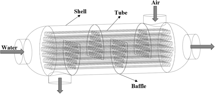
In this study, a shell and tube heat exchanger with single segmental baffle with a 25% baffle cut was used. The specifications and size of the heat exchanger are listed in Table 1. In this type of heat exchanger, air enters the shell from one side and water enters the tubes in the opposite direction. The tubes are arranged in a rotated triangular arrangement (Fig. 1).
Shell and tube heat exchanger with 25% single segmental baffle
Three different types of tubes were used in this study including elliptical tubes with an attack angle of 0°, elliptical tubes with an attack angle of 90° and normal circular tubes [28,29,30] (Fig. 2). All the tubes used in this study have the same perimeter.

The cross-sectional shape of the tubes: a elliptical tube with 0° angle attack; b elliptical tube with 90° angle attack; c circular tube
The heat exchanger geometry was drawn in three dimension using SolidWorks™ (V. 2017) (Fig. 3).

a Elliptical tube with 0° angle attack; b elliptical tube with 90° angle attack; c circular tube
The new shell and tube heat exchanger with different cross-sections was investigated. The combination used in this research includes elliptical tubes with an attack angle of 90° with circular tubes. The new arrangement of tubes was studied in two modes, (A) elliptical tubes with an attack angle of 90° in the center and circular tubes near the shell (STHE-ET90°&CT) and (B) circular tubes in the center and elliptical tubes with an attack angle of 90° near the shell (STHE-CT&ET90°). Figure 4 shows these two modes three dimensionally in SolidWorks (V. 2017).

a elliptical tubes with an attack angle of 90° in the center and circular tubes near the shell (STHE-ET90°&CT), b circular tubes in the center and elliptical tubes with an attack angle of 90° near the shell (STHE-CT&ET90°)
Thermophysical properties
In this study, air/water fluid was used to investigate the heat transfer coefficient and pressure drop in a shell and tube heat exchanger. Thermophysical properties of the fluid are given in Table 2 [31, 32].
A Reynolds number of 4000 was considered for different mass flow rates of air and water, which is calculated from Eq. (1). Therefore, the flow regime in the heat exchanger is turbulent and incompressible. A hot fluid (water) enters the tubes at 353.15 K while the cold fluid (air) enters the shell at 278.15 K. To evaluate the heat transfer and pressure drop, the hot and cold fluids with different mass flow rates of 0.38025, 0.57039, 0.76049, and 0.95061 kg/s for water 0.0039857, 0.0059794, 0.0079740, and 0.0099697 kg/s for air were considered. The fluid entered the tubes at atmospheric pressure and exited the shell at the same pressure. No-slip condition was also considered for the surface of tubes and shell. This boundary condition was used for numerical solution of the heat exchanger in the software:
\( \rho = {\text{water density}}\, 971.8 \,{\raise0.7ex\hbox{$W$} \!\mathord{\left/ {\vphantom {W {m\,K}}}\right.\kern-0pt} \!\lower0.7ex\hbox{${m\,K}$}}, \) \( u = {\text{water velocity}}\, 0.1 \,{\text{m/s}} \), \( D_{\text{H}} = {\text{Tube hydraulic diameter}}\, 0.015 \,{\text{m}} \), \( \mu = {\text{water dynamic viscosity in }}\,353.15 \,{\text{K}}\, 0.0003545 \,{\text{Pa}}\,{\text{s}} . \)
Mathematical model
COMSOL Multiphysics was used for numerical solution of the governing equations of heat transfer and pressure drop. First, the geometries drawn in SolidWorks™ were transferred to COMSOL. After specifying the type of fluid and heat exchanger, the governing equations for analyzing the heat transfer and pressure drop in the heat exchanger were selected, and boundary conditions were then applied to the software [33].
The diameter of circular tubes was considered 1.5 cm. Since the perimeter of circular and elliptical tubes is the same, the diameter of elliptical tubes with a ratio of 1:2 can be calculated from the following equation [34]:
\( a = 0.474 \, {\text{and}} \, b = 0.949. \)
It is well known that CFD solution in COMSOL is based on the Finite Element Method [35, 36].
The turbulent flow k–ɛ model was used to solve this problem. COMSOL uses the Navier–Stokes equations as the basic equations for solving the fluid flow models [33] as follows:
For turbulent kinetic energy, we can write as follows:
For dissipation,
For turbulent viscosity,
The constants used in the turbulent kinetic energy, turbulent viscosity and dissipation equations are set to the following values: \( C_{e1} = 1.44 \), \( C_{e2} = 1.92 \), \( C_{\mu } = 0.09 \), \( \sigma_{k} = 1 \) and \( \sigma_{\varepsilon } = 1.3 \).
The production of turbulent kinetic energy can be expressed as follows:
where u = fluid flow velocity, \( \rho \) = fluid density, p = fluid pressure, \( \mu \) = fluid dynamic viscosity, I = identity matrix, \( \nabla \) = del operator, T = stress tensor.
Mesh control
Due to the complex structure of shell and tube heat exchanger (STHE), unstructured tetrahedral, pyramid, prism, triangular and quadrilateral structures are produced while meshing the geometry. Meshing was done by COMSOL Multiphysics. To evaluate the type and number of appropriate meshes, a shell and tube heat exchanger with a 25% baffle cut with circular tubes was modeled with k–ε model at a Reynolds number of 4337 and a mass flow rate of 0.38025 kg/s. COMSOL automatically applies the optimal number of meshes for the near wall region. Seven different types of mesh of different sizes were investigated to determine the number of suitable meshes. The total number of meshes in these cases from larger meshes to smaller meshes was equal to (1,292,741; 1,165,641; 1,140,747; 1,055,370; 989,759; 886,459 and 791,018).
According to the results, the deviation of the overall heat transfer coefficient and the pressure drop of meshes of different sizes was less than 1.7% (Fig. 5). Since analysis was conducted on a 3D geometry, the use of higher number of meshes will increase the computational time. It can be concluded that this effect can be ignored from 1,140,747 meshes afterward. As a result, a mesh size of 1,140,747 was chosen for computational models (Fig. 6).

a Overall heat transfer coefficient in different meshes, b pressure drop in the shell in different meshes

The meshed model used in the numerical calculations of the heat exchanger with 1,140,747 meshes
For each number of meshes that were evaluated from different size of mesh element, we calculate heat transfer coefficient and pressure drop. Upon comparison of the results, the best mesh number can be selected for computational model (1,140,747). The maximum deviation of the mesh number was less than 1.7% for heat transfer coefficient (Fig. 6a) and 1.3% for pressure drop in shell side (Fig. 6b).
Model validation
We found no experimental model in open literature for validating data obtained from the software for the two new modes of tube arrangement. However, the common case of shell and tube heat exchanger with a simple segmental baffle of a baffle cut of 25% has been studied extensively. Comparison of the results obtained from the software with experimental results [37] indicates a very low difference of 5–8% (Fig. 7). In all the heat exchangers examined in this study, all the factors such as the type of fluid, governing equations, baffles, and type of flow were unchanged and only the shape of tubes was changed. Thus, it can be concluded that the results for the new cases in this study have an enough validity.

Comparison of the results obtained from the software and experimental model
Result and discussion
By changing the mass flow rate, different Re number can be obtained. Hence, we calculated models in different Re number in COMSOL software. The results at a Re number 8000 are illustrated in Figs. 8 and 9.
\( \rho = {\text{water density}}\, 971.8 \,{\text{W/m}}\,{\text{K}} \), \( u = {\text{water velocity}}\, 0.2 \,{\text{m/s}} \), \( D_{\text{H}} = {\text{Tube hydraulic diameter}}\,0.015 {\text{m}} \), \( \mu = {\text{water dynamic viscosity in }}\,353.15 {\text{K}}\,0.0003545 \,{\text{Pa}}\,{\text{s}} . \)

The temperature contour inside the shell and tubes of the shell and tube heat exchanger with circular tubes (STHE-CT)

The velocity contour at the cross-section of the shell and tube heat exchanger for the STHE-CT, STHE-ET0°, STHE-ET90°, STHE-ET90°&CT, STHE-CT&ET90°
Figure 8 shows the temperature contour inside the shell and tubes of the shell and tube heat exchanger with circular tubes at a Reynolds number of 8000.
Figure 9 shows the velocity contour at the cross-section of the shell and tube heat exchanger for all the cases in this study at a Reynolds number of 8000.
Heat transfer coefficient
The overall heat transfer coefficient is calculated by the following equation based on the flow rate and the temperature of the inlet and outlet fluids [37, 38]:
where Q represents the average heat flux between the cold and hot fluid and is obtained from the following equation [39]:
where mc = mass flow rate in cold fluid, mh = mass flow rate in hot fluid, Cpc = specific heat at constant pressure in the cold fluid, Cph = specific heat at constant pressure in the hot fluid, and \( \Delta T_{\text{m}} \) is the logarithm mean temperature difference for the cold and hot flows. The logarithm mean temperature difference for the shell and tube heat exchanger with one shell pass countercurrent flow is obtained from the following equation:
where t1 = tube side inlet temperature, t2 = tube side outlet temperature, T1 = shell side inlet temperature, T2 = shell side outlet temperature, and A, heat transfer surface on the tube side, is obtained from the following equation:
where N = number of tubes, do= outlet tube diameter, Lt = tube length.
The heat transfer coefficient for the shell and tube heat exchanger is obtained from the following equation [3, 40]:
where hi= heat transfer coefficients for the tube side, h = heat transfer coefficients for the shell side, k1 = thermal conductivity of the tube, di = inner diameters of the tube, do = outer diameters of the tube.
The highest overall heat transfer coefficient was obtained for STHE-CT&ET90° and STHE-ET90° arrangements, respectively. The lowest overall heat transfer coefficient was obtained for STHE-ET0° and STHE-CT arrangements, respectively. This indicates an increase in heat transfer in heat exchangers with elliptical tubes and an attack angle of 90° than elliptical tubes with an attack angle of 0° and circular tubes.
The overall heat transfer coefficient for STHE-CT&ET90° increased by 30% and 10% compared to STHE-ET0° and STHE-CT, respectively. The overall heat transfer coefficient for STHE-ET90° increased by 26% and 6% compared to STHE-ET0° and STHE-CT, respectively. As a result, the use of the STHE-CT&ET90° combined structure leads to only 5% increase in the heat transfer compared with the STHE-ET90° arrangement.
The overall heat transfer coefficient for the STHE-ET90°&CT arrangement decreased by 8% compared with STHE-CT&ET90°, but showed 24% increase as compared with STHE-ET0°. As a result, the use of the STHE-ET90°&CT combined arrangement leads to only 3% increase in heat transfer compared with STHE-CT arrangement.
Furthermore, from the above two conclusions, it can be established that tubes located near the shell have a greater impact on heat transfer compared with tubes located in the center of the shell.
The overall heat transfer coefficient in all the studied cases is compared in Fig. 10.

The overall heat transfer coefficient in the tube side of STHE-CT, STHE-ET0°, STHE-ET90°, STHE-ET90°&CT and STHE-CT&ET90°
Nusselt number
The Nusselt number was obtained for all the studied cases using the Eq. (13) and the simulation results. The Nusselt number variation diagram as a function of Reynolds number is depicted in Fig. 11. As shown in Fig. 12, the Nusselt number obtained in this study for the STHE-CT heat exchanger differs from the Nusselt number obtained from the experimental equation introduced by Gnielinski [6, 40] by 9%:

The Nu number variation as a function of Re in STHE-CT, STHE-ET0°, STHE-ET90°, STHE-ET90°&CT and STHE-CT&ET90°

Nusselt number from simulation vs. Nusselt number from the experimental equation for the STHE-CT heat exchanger
Pressure drop in shell side
The pressure drop in the shell side can be obtained using the following equation [3, 41]:
\( \Delta P = {\text{pressure drop in shell side}} \), \( Re_{\text{s}} = Re {\text{number in shell}} \), F = friction factor, Ds = Sell diameter, De = equivalent diameter for the triangular pitch, Nb = number of baffle, \( \rho = {\text{density of the fluid}} \), V = mean flow velocity, Pt =tube pith, do = outer diameters of the tube, um = velocity of the fluid, \( \mu = \) dynamic viscosity of the fluid.
The lowest and highest pressure drop was observed in the shell side of STHE-CT and STHE-CT&ET90°, respectively. The pressure drop in the shell side of STHE-ET0° and STHE-ET90°, respectively, increased by 57% and 70% compared with STHE-CT. This indicates an increase in pressure drop in the shell side of heat exchangers with elliptical tubes as compared with circular tubes.
The pressure drop in the shell side of the STHE-ET90°&CT combined arrangement increased by 67% compared to the STHE-CT, indicating the effect of the cross-sectional shape of the tubes in the center of the shell on the shell side pressure drop. Due to the use of elliptical tubes with an attack angle of 90° in the center of the shell in STHE-CT&ET90°, the pressure drop is very close to that in STHE-ET90° where all elliptical tubes are arranged with an attack angle of 90°.
The pressure drop in the shell side of the STHE-CT&ET90° combined arrangement increased by 80% compared to the STHE-CT. This confirms the impact of the cross-sectional shape of the tubes near the shell on the shell side pressure drop.
From the above two conclusions, it can be deduced that the cross-sectional shape of the tubes and their placement in the shell whether in the center or on the shell side are very effective in the shell side pressure drop.
Pressure drop in the shell for all the cases in this study is compared in Fig. 13.

Pressure drop in shell side of STHE-CT, STHE-ET0°, STHE-ET90°, STHE-ET90°&CT and STHE-CT&ET90°
Pressure drop in tube side
The pressure drop in the tube side can be calculated from the following equation [42]:
\( \Delta P = {\text{pressure drop in tube side}} \), \( Re_{\text{D}} = Re {\text{number in tube}} \), F =friction factor, Lt=tube length, di=inner diameters of the tube, Np=number of pass, \( \rho = {\text{density of the fluid}} \), V =mean flow velocity, um=velocity of the fluid, \( \mu = \) dynamic viscosity of the fluid.
The lowest and highest pressure drop was observed in the tube side of STHE-CT and STHE-ET90°, respectively. The pressure drop in STHE-ET0 ° increased by 28% compared to STHE-CT.
The pressure drop in the tube side of STHE-ET90°&CT and STHE-CT&ET90° combined modes, respectively, increased by 40% and 55% compared with STHE-CT. The pressure drop in the shell side of STHE-ET90° was 67% higher than in STHE-CT. This shows a lower increase in the pressure drop due to the use of two types of tubes with different cross sections.
As a result, the pressure drop increased in the tube side of circular tubes and elliptical tubes with an attack angel of 0° and 90°, respectively.
The pressure drop in tubes in the shell and tube heat exchanger in all the cases is presented in Fig. 14.

Pressure drop in the tube side of STHE-CT, STHE-ET0°, STHE-ET90°, STHE-ET90°&CT and STHE-CT&ET90°
Conclusion
The overall heat transfer coefficient and the pressure drop in the shell side and tube side of the shell and tube heat exchanger with simple segmental baffle with 25% baffle cut were examined by changing the cross-sectional shape of the tubes and introduction of new type of tube bundles consisting of tubes with circular cross-section and elliptical cross-section with an attack angle of 90°. The following results were obtained:
-
1.
Upon comparison between STHE-CT, STHE-ET0° and STHE-ET90°, minimum and maximum heat transfer coefficient was obtained in STHE-ET0° and STHE-ET90°, respectively. However, the result indicates that for STHE-ET90°, the maximum pressure drop occurs in tube and in shell.
-
2.
The highest overall heat transfer coefficient was obtained for STHE-CT&ET90° and STHE-ET90° arrangements, respectively. This indicates an increase in heat transfer in heat exchangers with elliptical tubes with an attack angle of 90° as compared with circular tube.
-
3.
Additional conclusion that was drawn from this analysis is the impact of tube location in heat transfer. The impact of tubes near the shell on the overall heat transfer coefficient is much higher than those in the center of the shell.
-
4.
STHE-CT and STHE-CT&ET90° showed the lowest and highest pressure drop in the shell side, respectively. The change in the cross-section of tubes from circular to elliptical caused an increase in the pressure drop in the shell side.
-
5.
The cross-sectional shape of the tubes and their location in the shell both in the center and on the shell side significantly affect the pressure drop in the shell side.
-
6.
The lowest and highest pressure drop was observed in the tube side of STHE-CT and STHE-ET90°, respectively. This indicates an increased pressure drop in the tube side in the elliptical tubes.
-
7.
The pressure drop in the shell side and tube side of elliptic tubes with an attack angle of 90° and 0° is higher than that in the circular tubes.
-
8.
Although STHE-CT&ET90° and STHE-ET90°&CT combined arrangements increase the heat transfer by 10% and 3%, respectively, compared to STHE-CT, they cause an increase in the pressure drop in the shell side, respectively, by 80% and 67% and lead to 55% and 40% increase in the tubes side compared with STHE-CT.
References
Yang, J.-F., Zeng, M., Wang, Q.-W.: Numerical investigation on shell-side performances of combined parallel and serial two shell-pass shell-and-tube heat exchangers with continuous helical baffles. Appl. Energy 139, 163–174 (2015)
Labbadlia, O., Laribi, B., Chetti, B., Hendrick, P.: Numerical study of the influence of tube arrangement on the flow distribution in the header of shell and tube heat exchangers. Appl. Therm. Eng. 126, 315–321 (2017)
He, Z., Fang, X., Zhang, Z., Gao, X.: Numerical investigation on performance comparison of non-Newtonian fluid flow in vertical heat exchangers combined helical baffle with elliptic and circular tubes. Appl. Therm. Eng. 100, 84–97 (2016)
Ayub, Z.H., Yang, D., Khan, T.S., Al-Hajri, E., Ayub, A.H.: Performance characteristics of a novel shell and tube heat exchanger with shell side interstitial twisted tapes for viscous fluids application. Appl. Therm. Eng. 134, 248–255 (2018)
Qiu, Y., Li, M.-J., Wang, W.-Q., Du, B.-C., Wang, K.: An experimental study on the heat transfer performance of a prototype molten-salt rod baffle heat exchanger for concentrated solar power. Energy 156, 63–72 (2018)
Ibrahim, T.A., Gomaa, A.: Thermal performance criteria of elliptic tube bundle in crossflow. Int. J. Therm. Sci. 48(11), 2148–2158 (2009)
Horvat, A., Leskovar, M., Mavko, B.: Comparison of heat transfer conditions in tube bundle cross-flow for different tube shapes. Int. J. Heat Mass Transf. 49(5–6), 1027–1038 (2006)
Fazelpour, F., Vafaeipour, M., Rahbari, O.: CFD simulation of hydrodynamics of gas-solid two-phase flow for different geometries of solid particles. The 5th International Congress of Energy and Environment Engineering and Management, Lisbon (2013)
Bonilla, J., de la Calle, A., Rodríguez-García, M.M., Roca, L., Valenzuela, L.: Study on shell-and-tube heat exchanger models with different degree of complexity for process simulation and control design. Appl. Therm. Eng. 124, 1425–1440 (2017)
Skoglund, T., Årzén, K.-E., Dejmek, P.: Dynamic object-oriented heat exchanger models for simulation of fluid property transitions. Int. J. Heat Mass Transf. 49(13–14), 2291–2303 (2006)
Zaversky, F., Sánchez, M., Astrain, D.: Object-oriented modeling for the transient response simulation of multi-pass shell-and-tube heat exchangers as applied in active indirect thermal energy storage systems for concentrated solar power. Energy 65, 647–664 (2014)
Shahdad, I., Fazelpour, F.: Numerical analysis of the surface and geometry of plate fin heat exchangers for increasing heat transfer rate. Int. J. Energy Environ. Eng. 9(2), 155–167 (2018)
Xie, S., Liang, Z., Zhang, L., Wang, Y.: A numerical study on heat transfer enhancement and flow structure in enhanced tube with cross ellipsoidal dimples. Int. J. Heat Mass Transf. 125, 434–444 (2018)
Matos, R., Laursen, T., Vargas, J., Bejan, A.: Three-dimensional optimization of staggered finned circular and elliptic tubes in forced convection. Int. J. Therm. Sci. 43(5), 477–487 (2004)
Matos, R., Vargas, J., Laursen, T., Bejan, A.: Optimally staggered finned circular and elliptic tubes in forced convection. Int. J. Heat Mass Transf. 47(6–7), 1347–1359 (2004)
Matos, R., Vargas, J., Laursen, T., Saboya, F.: Optimization study and heat transfer comparison of staggered circular and elliptic tubes in forced convection. Int. J. Heat Mass Transf. 44(20), 3953–3961 (2001)
Bouris, D., Papadakis, G., Bergeles, G.: Numerical evaluation of alternate tube configurations for particle deposition rate reduction in heat exchanger tube bundles. Int. J. Heat Fluid Flow 22(5), 525–536 (2001)
Nouri-Borujerdi, A., Lavasani, A.: Experimental study of forced convection heat transfer from a cam shaped tube in cross flows. Int. J. Heat Mass Transf. 50(13–14), 2605–2611 (2007)
Nouri-Borujerdi, A., Lavasani, A.M.: Pressure loss and heat transfer characterization of a cam-shaped cylinder at different orientations. J. Heat Transfer 130(12), 124503 (2008)
Moawed, M.: Experimental study of forced convection from helical coiled tubes with different parameters. Energy Convers. Manag. 52(2), 1150–1156 (2011)
Rosen, M., Dincer, I.: Exergy methods for assessing and comparing thermal storage systems. Int. J. Energy Res. 27(4), 415–430 (2003)
Mohanty, R.L., Swain, A., Das, M.K.: Thermal performance of mixed tube bundle composed of circular and elliptical tubes. Therm. Sci. Eng. Progress 5, 492–505 (2018)
Harris, D.K., Goldschmidt, V.W.: Measurements of the overall heat transfer from combustion gases confined within elliptical tube heat exchangers. Exp. Thermal Fluid Sci. 26(1), 33–37 (2002)
Khan, M.G., Fartaj, A., Ting, D.S.-K.: An experimental characterization of cross-flow cooling of air via an in-line elliptical tube array. Int. J. Heat Fluid Flow 25(4), 636–648 (2004)
Li, Z., Davidson, J., Mantell, S.: Numerical simulation of flow field and heat transfer of streamlined cylinders in crossflow. In: ASME 2005 Summer Heat Transfer Conference collocated with the ASME 2005 Pacific Rim Technical Conference and Exhibition on Integration and Packaging of MEMS, NEMS, and Electronic Systems 2005, pp. 531–541. American Society of Mechanical Engineers
Li, B., Feng, B., He, Y.-L., Tao, W.-Q.: Experimental study on friction factor and numerical simulation on flow and heat transfer in an alternating elliptical axis tube. Appl. Therm. Eng. 26(17–18), 2336–2344 (2006)
Tao, Y., He, Y., Wu, Z., Tao, W.: Three-dimensional numerical study and field synergy principle analysis of wavy fin heat exchangers with elliptic tubes. Int. J. Heat Fluid Flow 28(6), 1531–1544 (2007)
Pal, E., Kumar, I., Joshi, J.B., Maheshwari, N.: CFD simulations of shell-side flow in a shell-and-tube type heat exchanger with and without baffles. Chem. Eng. Sci. 143, 314–340 (2016)
Markowski, M., Trafczynski, M., Urbaniec, K.: Identification of the influence of fouling on the heat recovery in a network of shell and tube heat exchangers. Appl. Energy 102, 755–764 (2013)
Yang, J., Fan, A., Liu, W., Jacobi, A.M.: Optimization of shell-and-tube heat exchangers conforming to TEMA standards with designs motivated by constructal theory. Energy Convers. Manag. 78, 468–476 (2014)
Dinçer, İ., Zamfirescu, C.: Appendix B Thermophysical Properties of Water. Drying Phenomena: Theory and Applications, pp. 457–459
Hilsenrath, J.: Tables of Thermodynamic and Transport Properties of Air, Argon, Carbon Dioxide, Carbon Monoxide, Hydrogen, Nitrogen, Oxygen, and Steam. Pergamon Press, Oxford (1960)
Multiphysics, C.: Comsol multiphysics user guide (version 4.3 a). COMSOL, AB, 39-40 (2012)
Oberg, E.: Machinery’s Handbook 29th Edition-Full Book. Industrial Press, New York (2012)
Pepper, D.W., Heinrich, J.C.: The Finite Element Method: Basic Concepts and Applications. Taylor & Francis, Abingdon (2005)
Zimmerman, W.B.: Multiphysics Modeling with Finite Element Methods, vol. 18. World Scientific Publishing Company, Singapore (2006)
El Maakoul, A., Laknizi, A., Saadeddine, S., El Metoui, M., Zaite, A., Meziane, M., Abdellah, A.B.: Numerical comparison of shell-side performance for shell and tube heat exchangers with trefoil-hole, helical and segmental baffles. Appl. Therm. Eng. 109, 175–185 (2016)
Azar, R.T., Khalilarya, S., Jafarmadar, S.: Tube bundle replacement for segmental and helical shell and tube heat exchangers: experimental test and economic analysis. Appl. Therm. Eng. 62(2), 622–632 (2014)
Allen, B., Gosselin, L.: Optimal geometry and flow arrangement for minimizing the cost of shell-and-tube condensers. Int. J. Energy Res. 32(10), 958–969 (2008)
Kumar, N.R., Bhramara, P., Kirubeil, A., Sundar, L.S., Singh, M.K., Sousa, A.C.: Effect of twisted tape inserts on heat transfer, friction factor of Fe3O4 nanofluids flow in a double pipe U-bend heat exchanger. Int. Commun. Heat Mass Transfer 95, 53–62 (2018)
Gaddis, E.S., Gnielinski, V.: Pressure drop on the shell side of shell-and-tube heat exchangers with segmental baffles. Chem. Eng. Process. 36(2), 149–159 (1997)
Kakac, S., Liu, H., Pramuanjaroenkij, A.: Heat Exchangers: Selection, Rating, and Thermal Design. CRC Press, Boca Raton (2012)
Author information
Authors and Affiliations
Corresponding author
Additional information
Publisher's Note
Springer Nature remains neutral with regard to jurisdictional claims in published maps and institutional affiliations.
Rights and permissions
Open Access This article is distributed under the terms of the Creative Commons Attribution 4.0 International License (http://creativecommons.org/licenses/by/4.0/), which permits unrestricted use, distribution, and reproduction in any medium, provided you give appropriate credit to the original author(s) and the source, provide a link to the Creative Commons license, and indicate if changes were made.
About this article

Cite this article
Saffarian, M.R., Fazelpour, F. & Sham, M. Numerical study of shell and tube heat exchanger with different cross-section tubes and combined tubes. Int J Energy Environ Eng 10, 33–46 (2019). https://doi.org/10.1007/s40095-019-0297-9
Received:
Accepted:
Published:
Issue Date:
DOI: https://doi.org/10.1007/s40095-019-0297-9