
Abstract
In order to determine the overall safety of a tunnel support lining, a reliability-based approach is presented in this paper. Support elements in jointed rock tunnels are provided to control the ground movement caused by stress redistribution during the tunnel drive. Main support elements contribute to stability of the tunnel structure are recognized owing to identify various aspects of reliability and sustainability in the system. The selection of efficient support methods for rock tunneling is a key factor in order to reduce the number of problems during construction and maintain the project cost and time within the limited budget and planned schedule. This paper introduces a smart approach by which decision-makers will be able to find the overall reliability of tunnel support system before selecting the final scheme of the lining system. Due to this research focus, engineering reliability which is a branch of statistics and probability is being appropriately applied to the field and much effort has been made to use it in tunneling while investigating the reliability of the lining support system for the tunnel structure. Therefore, reliability analysis for evaluating the tunnel support performance is the main idea used in this research. Decomposition approaches are used for producing system block diagram and determining the failure probability of the whole system. Effectiveness of the proposed reliability model of tunnel lining together with the recommended approaches is examined using several case studies and the final value of reliability obtained for different designing scenarios. Considering the idea of linear correlation between safety factors and reliability parameters, the values of isolated reliabilities determined for different structural components of tunnel support system. In order to determine individual safety factors, finite element modeling is employed for different structural subsystems and the results of numerical analyses are obtained in different design scenarios. Finally, the reliability index values are obtained for the entire support structure in different design scenarios. The results of the work demonstrates that proposed reliability evaluation method of tunnel support system is effective not only for investigating the reliability of individual elements in the structure, but also for building an overall estimation about reliability performance of the entire tunnel structure.
Introduction
Tunnel linings are structural systems, but differ from other structural systems in that their interaction with the surrounding ground is an integral aspect of their behavior, stability and overall load carrying capacity. The loss or lack of the support provided by the surrounding ground can lead to failure of the lining. The ability of the lining to resist under load is a function of the relative resistance of the lining and the surrounding ground. The tunnel lining system allows the pressure around the tunnel to redistribute in the most efficient way. In fact, a tunnel lining maintains its stability and load carrying capacity through contact with the surrounding ground (FHWA 2009).
Structural support system should be precisely calculated in the design stage and then monitored in the construction phase of tunneling, since tunnels are expensive and are constructed for long-term use. Selecting efficient support methods for the tunnels leads both cost and time to remain within the project budget and schedule. Having a tunnel out of service for an extended period of time can result in great economic loss. As such, details and materials should be selected that can withstand the conditions encountered in underground structures. Therefore, an appropriate support system should be selected by acceptable engineering methods, of which reliability method can be considered. The design of tunnel linings, with the exception of steel tunnel lining plates, is not separately addressed in standard design codes. Generally, usual structural design codes, such as AASHTO LRFD Bridge Design Specifications are being used as the main standard for design of tunnel support system. Some complementary codes such as FHWA (2005, 2009) are also intended to establish procedures for the design of tunnel linings.
Conventional stability analysis and limit equilibrium methods are commonly being used by structural designers to assess the stability of tunnel structures which is mainly based on design codes. Several examples of tunnel structural design using conventional stability analysis and deterministic design procedures can be found in Rasouli (2009) and Dehghan et al. (2012).
By the way the application of reliability engineering in tunnel support design is not still a clear topic in the literature. Generally speaking, many uncertainties may be present in the tunnel support condition once a tunnel is to be constructed. This nondeterministic situation even begins at the first stage of tunnel design once the location for the structure is going to be identified. Different estimations about mass properties naturally can have essential effects on tunnel design (Hoek 1998). For the successful completion of the tunnel construction and performance, it is important to account for these uncertainties in design. However, despite recent advances in the developments of tunneling methods, it is still difficult to assess the probabilistic properties accurately due to these uncertainties. The design of the tunnel supports ignoring such uncertainties could be subject to large error. On the other hand, designs with large safety factors to counteract the effect of uncertainties may become too conservative. Probabilistic concepts may be introduced in the tunnel support design to incorporate the effect of uncertainties on design level.
The application of reliability engineering in this article is based on probabilistic evaluation to find the entire reliability of the system using corresponding reliabilities in the components; however, the method for calculation of individual reliabilities in the elements is a kind of deterministic approach since it is using the results of finite element simulations and numerical calculations for estimation of factor of safety. The purpose of this study is therefore, to introduce a methodology to apply probabilistic features in the tunnel structure design based on design safety factors which are considered in the calculation stage of tunnel structure which is usually being dome using the numerical results of the FE analyses. Thereafter, the reliability results are obtained both for individual components and entire tunnel structure.
Application of reliability in tunnel engineering
The simplest definition of the term reliability is the probability of a desirable and sustainable function of a system. Engineering reliability, as in mathematics, is a basic science which may be used in other branches such as tunneling (Kaveh and Kalat 1995). Since years ago, many researchers have been dealing with the issue of reliability of structures. Also, some researchers have tended to work on reliability in geotechnical structures. Various methods for application of reliability analysis in engineering problems can be found out in Dai and Wang (1992). There are also some references that indicate the application of reliability engineering specifically on geotechnical engineering. Reliability analyses, involving neither complex theory nor unfamiliar terms, can be used in routine geotechnical engineering practice. These reliability analyses require little effort beyond that involved in conventional geotechnical analyses. Baecher and Christian (2003) reported many fundamental approaches for reliability practices in geotechnical field. More recently, Simpson (2011) proposed fundamental tools for calculation of reliability in geotechnical design. Duncan (2000) also did a comprehensive study on the factors of safety and reliability in geotechnical engineering.
Reliability evaluation can provide a means of evaluating the combined effects of uncertainties in the parameters involved in the calculations, and offer a useful supplement to conventional structural analyses. In general, after excavating a new tunnel, the ability for tolerating the existing loads of materials around the tunnel is very important. Therefore, tunnels must be protected against these loads using appropriate structural system. Engineering reliability is based on the principles of probability and mathematics which is now a useful tool for estimating the proper function of systems. System reliability which is expressed in percentage is the probability of efficient and expected system performance without damage and destruction (Dai and Wang 1992).
Since the tunnel is a sample of geotechnical structures, many researches in the literature addressed the uncertainty issue of the tunnel structure toward nondeterministic behavior of surrounding ground. As an example, Kohno et al. (1992) showed that the reliability of a tunnel system within one type of rock would depend upon the characteristics of the ground along the tunnel axis and the reliability of a cross section. The effect of alternating rock types along the tunnel axis upon the reliability of the tunnel system is investigated by them.
A practical procedure for applying probabilistic stability analysis of structures is presented by Xu and Low (2006) first for analysis of embankments. Several years later, Li and Low (2010) followed by Lu and Low (2011) applied a similar probabilistic analysis into underground rock excavations (circular tunnel structure) using response surface method and SORM. They evaluated the response surface using the probability of failure by first-order and the second-order reliability method (FORM/SORM). Independent standard normal variables are chosen by them as basic random variables and transformed into correlated non-normal variables in the original space of random variables for constructing the response surface. Also a practical method for calculation of second moment reliability index using spreadsheets was previously reported by the members of this research group (Low and Tang 1997). Then the reliability analyses involving non-normal distributions are investigated by them. In a relatively similar research, Mollon et al. (2009a, b) performed a probabilistic analysis and design of circular tunnels against face stability using response surface methodology. More research studies on the application of first and second-order reliability method in structural analysis can be found in Cai and Elishakoff (1994).
Laso et al. (1995), Celestino et al. (2006) and Shin et al. (2009) worked on the reliability of tunnel support mostly based on tunnel–ground interaction problem. Laso et al. (1995) used a reliability-based mathematical approach for tunnel support design. They applied classical reliability techniques to tunnel design method based on the study of the ground-support interaction diagram.
In a relatively similar research topic Schweiger et al. (2001) proposed a comprehensive procedure for combining probabilistic concepts and deterministic finite element methods for geotechnical analysis. They employed Bayes’ theorem to arrive at input parameters for the calculations combining different sources of information. Then A Taylor Series is adopted by them to identify the most important input parameters, and, consequently, a point estimate method (PEM) together with a finite element model for a particular problem in geotechnical engineering. Another sophisticated reliability application based on mathematical methods can also be found in Tsai and Franceschini (2005) which is applicable for any problem in environmental engineering.
Considering the idea of uncertainty in ground condition, Kohno et al. (1992) considered shotcrete, rock bolts and steel-rib for tunnel support system and attempted to propose some probabilistic models in the design of tunnel supports through the statistically homogeneous ground. Then the authors determined the reliability of the tunnel system within the correlation analysis in characteristics of the ground along the tunnel axis and the reliability of tunnel cross-section. The effect of alternating rock types around the tunnel upon the reliability of the tunnel system is also investigated by them.
Among reliability practices in tunnel engineering, Kitamura and Kojo (1988) showed that tunnel linings safety may be estimated based on the reliability theory. Other researchers such as Yang and Zhang (1999) and Frangopol et al. (2009) paid attention to the problem of structures optimization with the reliability approaches.
Reliability methods are also applicable for tunnels during or after construction. Yang et al. (2007) and Yang and Zhang (1999) worked on assessment of the stability of the lining through in situ measured data for the observational designing of the tunnel and to guarantee the safety of construction. They developed a displacement-based method suitable for conducting reliability evaluation of the shotcrete lining in the progress of construction of the tunnel.
Some researchers concentrated on the probabilistic selection of appropriate rock quality in tunnel surrounding area. Oreste (2005) performed a probabilistic calculation and used some design tools for tunnel supports. His probabilistic approach, have sufficient data on the quality of the rock mass around the tunnel to, leads to better understanding the risks, more efficient geomechanical zoning and finally more reliable estimation of the costs.
Some researchers applied probabilistic investigations on structural design phenomena. Using Monte Carlo simulations, Celestino et al. (2006) obtained the margin of safety of tunnel structure to evaluate the probability of failure according to load and resistance factor design principles for the failure modes. By varying tunnel support parameters, the distribution of tunnel strength capacity was obtained, and compared to the load obtained from the finite element analysis. In a relatively similar work, Langford and Diederichs (2013) presented a reliability-based design approach to evaluate the performance of a composite tunnel lining using a modified Rosenblueth point estimate method (PEM), first order reliability method (FORM), Monte Carlo sampling method and finite element analysis. The support performance of one example tunnel has been studied by these authors.
Lu et al. (2011, 2013) presented a procedure for assessing the system reliability of a rock tunnels. They recognized tree failure modes, namely, inadequate support capacity, excessive tunnel convergence, and insufficient rock bolt length and evaluated the failure probability of each failure mode using a deterministic model of ground-support interaction.
Some researchers applied techniques of risk analysis in tunnel safety evaluation. You et al. (2005) proposed a methodology to determine an optimal support pattern and advance rate for the design of a tunnel based on risk analysis. They quantitatively showed that the more the tunnel is supported, the higher the reliability index becomes and the more stable the tunnel is predicted to be. These articles and similar works considered the risk analysis for determining the tunnel support system. Holicky (2009) applied probabilistic methods of risk optimization to identify the most effective safety measures considered in the design of road tunnels. The total consequences of alternative tunnel arrangements were assessed by him using Bayesian networks supplemented by decision nodes. He showed that the probabilistic optimization may provide valuable information enabling effective safety measures in tunnels.
As it is briefly described, in most of the previous research lines, reliability of certain components of the tunnel has been studied separately toward nondeterministic conditions. For instance Lu et al. (2013) considered rock bolts in the analysis and Yang et al. (2007) mainly focused on shotcrete in their reliability analysis. However, the issue of reliability of the overall tunnel support system with regard to all the assembled components is still untreated in the literature which was investigated in the present work.
Considering the above literature review, it can be seen that many researchers previously worked on the topics of uncertainty in ground conditions and rock quality evaluation around the tunnel face in connection with mechanical properties or geotechnical investigations. As an intrinsic conceptual difference between current study and previous works, these kinds of problems are not addressed in the current study and the proposed reliability model is only consisting of elements in tunnel lining system. Hence this paper examines the reliability of structural support system for the tunnels excavated in jointed rocks. In order to consider all possible structural elements for primary and final tunnel support system, ground type with highly jointed rock situation is considered for as the material around the tunnel. To establish reliability modeling for tunnel structure as the main idea of this study, first, components of the tunnel support system and their specifications are recognized and then, the relationships between these components are identified. Afterward, the most important components of an idealized tunnel support lining distinguished and finally performance reliability of tunnel structure introduced.
The reliability methods which are introduced in this paper are now new approaches and their general methodologies can be found in fundamental books of reliability engineering like Dai and Wang (1992), Ebeling (1997) or Kececioglu (1991). However, the application of these methods in tunnel support design is evidently new and such an idea is proposed for the first time by the authors in order to evaluate the overall reliability of structural support system for tunnels. The main purpose of this paper is to identify the performance relationship between various structural support components leading to the stability of tunnel structure. Using this idea, the total reliability of the system is calculated dependent on the individual reliabilities (On components level) in incorporating elements. It should be noted that the initial idea of the work was previously introduced by Gharouni-Nik and Naeimi (2009), proposing an introduction to mathematical equations and general terminology of the reliability in tunnel structure. Hereby in this article the detailed methodology is described and the main procedure is established based on several case studies. A general methodology to calculate isolated reliabilities for tunnel structural components is additionally proposed in this work for the first time.
Components of tunnel support system
Reliability modeling is the process of predicting or understanding the reliability of the components of the system prior to its implementation. In order to build the reliability model together with estimating the input parameters for this model it is essential to determine various components (parts) of the system and to provide appropriate estimation for their relationships (Kececioglu 1991, 1997). Different parts of the tunnel support system are identified in this section.
Tunnel linings are structural systems installed after (or during) excavation to provide ground support, to maintain the tunnel opening, to limit the inflow of ground water, to support appurtenances and to provide a base for the final finished exposed surface of the tunnel. Tunnel linings can be used for initial stabilization of the excavation, permanent ground support or a combination of both. The main materials for tunnel linings are cast-in-place concrete lining, precast segmental concrete lining, steel plate linings and shotcrete lining. However, depending on the location and loading condition, other elements may also be adopted for the lining system. When a tunnel is excavated in different ground conditions, it is an inevitable consequence that some form of support will be required if the tunnel is to retain adequate stability and maintain sufficient resistance against surrounding loads in the intended manner. The form and function of the tunnel support system will vary according to a wide range of factors apart from just geotechnical considerations and it would seem that for every different tunnel there is a different lining solution (FHWA 2009; Kuesel et al. 2004).
In order to discuss the overall safety of a tunnel support system, it is necessary to consider the reliability of the incorporating elements of the tunnel system since the failure of a tunnel structure is normally initiated by the failure in the structural elements. Various components of structural support system for the tunnels which are excavated in jointed rocks with weak ground condition are mainly divided to five types. Structural configuration of tunnel lining system in rock is consisting of several or all of these components. Similar incorporating elements are also used for the tunnels that are excavating in soil material. However, the main effort in this article is concentrated on tunnels in jointed rock circumference as a sample of loose ground condition. Figure 1 shows the general supporting system of a tunnel excavated in jointed ground condition. Depending on structural behavior of the tunnel lining and ground condition, it might be necessary to use some kind of steel frames in zones with weak ground condition. To represent this issue, the tunnel in Fig. 1 contains also several sections with steel frames in the whole length of tunnel which depicted this figure. Details 1–5 which are addressed in this figure are relevant to the incorporating elements of the tunnel support system briefly explained hereunder.

General supporting system of a tunnel excavated in jointed ground condition, details 1–5 are presented in next figures, left 3D view of the tunnel, middle a section with steel frames, right a section without steel frames
Rock bolts
In ground with good stand-up times, ribs and lagging or rockbolting can be used as the temporary support followed by a cast in situ primary concrete lining or precast segments. Various bolt components are available for tunnel engineering including steel dowels, wire cables, steel rods, etc., with tensioned of frictional behavior. These elements are usually bonded to the ground by means of grouting application. Rock bolts are components which are used for connecting the local rock around the tunnel either to each other or to deeper layers of surrounding ground. General configuration of rock bolt system and its components are presented in Fig. 2.

General configurations of rock bolt system and its components
As indicated in Fig. 2, rock bolt system itself contains two other components failure which cause failure in rock bolts. These components include:
-
Bar elements or steel rods (BE)
-
Epoxy glue or cement material around the bars (epoxy binder, EB)
Rock bolts will not work properly when starting to failure. So, both of them are needed for a desirable function of the system. Reliability of each element will be displayed by RBE and REB, respectively.
Generally, reliability of rock bolts depends on different factors such as level of stress imposed by force or their environmental conditions. In this paper, the probability of failure for each section occurred under various conditions and it was supposed that they work properly with no failure rate.
Wire meshing
This type of tunnel support system often used in conjunction with shotcrete layer as the temporary support for tunnel support system. Wire meshing is basically formed by a series of thin junction bars which are welded (or mechanically fastened) together and increases the tensile strength of tunnel lining. Figure 3 represents the configuration of embedded wire mesh elements in shotcrete layer in primary support system.

General configurations of embedded wire mesh elements in shotcrete layer
As depicted in Fig. 3, wire meshing system includes two subsystems the failure of each will fail the whole system. These subsystems are:
-
Quality of meshing rods (mesh wires, MW),
-
Method of installing and fastening the mesh on tunnel walls (mesh installation, MI).
Reliability of the elements will be displayed by RMW and RMI, respectively.
Shotcrete (sprayed concrete)
In rock tunnels where the ground has insufficient stand-up time to allow the construction of the primary lining some distance behind the face, then some form of temporary ground support applied at the tunnel face is required, e.g., rock bolts, shotcrete and steel sets. Thin shotcrete layer as the concrete coating is one of the most important components of tunnel structural support which cover the tunnel surface thoroughly. Shotcrete can even be considered as the final lining in structural system. General application of shotcrete layer is shown in Figs. 2 and 3 in conjunction with wire mesh and rock bolt components.
It is worth mentioning that reliability analysis of this element depends on previous elements. So, it should be noted that, based on new Austrian tunneling method (NATM), rock bolts and wire meshes are tightly connected to shotcrete and the failure of these three elements will usually happen together. The modeling process of this linked relationship will be discussed in the next sections. The reliability of shotcrete covering layer will be shown by RSC.
Concrete lining
Various tunnels require smooth longitudinal profiles for their intended use, e.g., sewer and water tunnels or aesthetic finishes for public transportation usage, i.e., highway and railway tunnels. Erosion and corrosion protection for the primary lining and further waterproofing may also be required, all of which are provided by secondary lining either a poured or precast concrete lining. There are various methods available to provide secondary or final support system of tunnels among them precast and cast in place concrete lining are the most prevalent. In soft ground conditions where a shield-driven tunnel is required, some form of precast segmental lining will be required, either bolted or unbolted. Conversely, if the tunnel has an appreciable stand-up time allowing dispensing of the tunneling shield, then the use of molding and cast in place concrete may be appropriate.
Figure 4 demonstrates the general cross section of concrete lining as the final support system both for cast in place concreting and segmental precast concrete.

General cross section of concrete lining as the final support system, left cast in place concreting, right segmental precast concrete
In precast concrete lining approach on the one hand, thickness of these blocks is generally more than that of shotcrete layer and they are usually applied when there are weak rocks around the tunnel. Concrete blocks act in series with other support components and designers usually consider high reliability for this element of support unless they cause damage in the tunnel.
Concrete blocks have two subsystems that are both parallel. These subsystems are:
-
Bolts connecting the blocks (connecting bolt, CB),
-
Main blocks or concrete segments (key block, KB).
Reliability of these elements will be displayed by RCB and RKB, respectively. Concrete segments are connected to each other by special bolts and strong cohesive materials such as cement or epoxy adhesives. The concrete segments (key blocks) also play an important role in stability of the tunnel. Therefore, the main concrete blocks act in parallel with the connecting bolts. Since the whole series of connected concrete blocks are too heavy, big damage would be imposed on the tunnel performance in case of any failure. This is why the series of segments are considered in conjunction with other elements of support.
For the case of in situ concreting on the other hand, reliability of whole concrete layer is considered as RCL which represents the effective performance of the whole lining system.
Steel sets
Application of the steel arch support systems and rock bolts are the most commonly applied forms of support in rock mining excavations. Steel frame is one of the strongest elements of tunnel support system used for the fractured rocks with low resistance. This type of tunnel structural support system consists of several pieces of steel profiles jointed to each other in order to make the frame. Figure 5 indicates the general configuration of steel frames in tunnel section together with their arrangement and connecting joints. This system as shown in this figure has the following two subsystems which together have a series probability. Failure of each steel frame is caused by the simultaneous failure of these subsystems:
-
Steel pieces connected to each other (steel element, SE),
-
Joints between the elements (common joints, CJ).

General configurations of steel frames in tunnel section, their arrangement and connecting joints
Reliability of each of these elements will be displayed by RSE and RCJ, respectively. Generally, steel frames are designed for heavy loads and they may cause serious damage to the entire tunnel structural system in case of failure. Therefore, the reliability of these elements should be as high as possible to avoid problems for the tunnel.
Modeling of the system and its subsystems
Based on above description, general performance of the tunnel structural support system can be summarized as in the diagram shown in Fig. 6. Letters and abbreviations which are later used in this article are also defined briefly in the figure. As shown in the diagram, all the components are defined without considering their linked relationship.

Performance diagram of tunnel structural support system and abbreviations for incorporating elements
Block diagram of system reliability
For any system, one of the first tasks of reliability engineering is to adequately specify the effective components of reliability for the whole system. Reliability requirements should drive a (system or part) design to incorporate features that prevent failures from occurring or limit consequences from failure in all parts of the system. Reliability design begins with the development of the system model. Reliability models use block diagrams to provide a graphical means of evaluating the relationships between different parts of the system. These models may incorporate predictions based on failure rates taken from historical data (Kececioglu 1991; Ebeling 1997). The reliability block diagram of the tunnel support system (extracted from the diagram of Fig. 6) which depicts the relationship between system components is being explained in this section. First of all, there are relationships between the four subsystems of EB, BE, MW and MI. As the normal procedure for reliability analysis, these relations should be appropriately identified to draw the block diagram of the system’s reliability. The only technique to identify these relations is checking physical redundancy of subsystems in the model. This means that if one part of the system fails, whether there is an alternate success path, such as a backup subsystem to maintain the system reliable. This is a kind of physical design perception from subsystems related to their reliability for the whole system.
At the moment there are not enough evidences for establishment of these relationships for parts/items of the reliability in the tunnel support system. These kinds of data (records for failure of the subsystems) are often not available or extremely expensive to obtain. So the reliability model of this study can be considered as a tentative reliability model that needs to be examined and verified later by available records for failure in tunnel support elements (failure monitoring). In order to define this tentative reliability model, initial perceptions for performance of the subsystems in tunnel linings are identified. The explanations for these relationships are as follows:
-
As mentioned previously, according to conceptual duty of rock bolt systems, it can be identified that rock bolts (RB) will fail with the failure of each of its subsystems, i.e., bar element (BE) and epoxy binder (EB). This failure seems to be essential and may break the support system down. However, the failure in rock bolts alone may not cause total damage to the entire tunnel support system. Therefore, this section can be considered in parallel (redundant elements) with the wire mesh performance. So, two members of EB and BE may be considered as one cut set (cutting path).
-
The description related to the wire mesh (WM) shows that failure of each subsystem (MW and MI) causes failure in the WM member. However, the failure of steel wire mesh alone may not cause damage to the whole tunnel support system. Therefore, this section must be considered in parallel (redundant) with other subsystems. So, the combination of two members, MW and MI, may also be considered as another cut set.
-
The layer of shotcrete (SC) has the role of covering and early strengthening of materials around the tunnel structure. Also its failure alone may not cause damage to the entire tunnel system; however, if the shotcrete layer (SC), bar element (BE) and mesh installation (MI) fail simultaneously (removing all redundant options), the entire system will collapse. So, three members of BE, SC and MI may be considered as one cut set as well.
-
With the same justification, if three members of mesh wires (MW), shotcrete (SC) and epoxy binder (EB) start to fail, overall failure will happen in the entire system. So, three members of MW, SC and EB may also be considered as one cut path.
-
As the predefined duty of steel set subsystem shows, these elements are essential for the stability of whole tunnel structure, so they may be defined as serial inputs (CE and CJ) in the whole block diagram.
-
The concrete lining system is responsible for the stability of final lining and can be identified as the serial subsystem; however, its two sub-elements (KB and CB) can be considered parallel (redundant) for the case of precast concrete segments.
Thus, the block diagram related to the members of the system and related subsystems can be extracted as in Fig. 7.

Block diagram of tunnel structural support system (relation among components)
Dashed lines in Fig. 7 show the main items of tunnel support system. They shall be hided and the entire system can be represented as the full diagram in Fig. 8. As can be observed, some subsystems act in parallel form while others act in series. Parallel elements show that if one part of the system fails, there is an alternate success path, such as a backup subsystem for the successful performance. Conversely, serial sub-elements stand for non-redundant options and reliability of the system will in this case be affected directly by their reliability. As described previously the block diagram of the system here is conceptually extracted based on general duty that defined for various components. The proposed model is flexible for any change in number of components or their relations; however, these changes will modify the mathematical equations corresponding to them. (See next section).

Final block diagram of tunnel structural support system (overall failure mechanism)
Calculating reliability of the system
Reliability analysis often needs to be implemented on systems having elements connected in parallel and series to calculate their reliability. To this end, when a system consists of a combination of series and parallel segments, convoluted block reliability formulas can be applied based on underlying statistical theory behind the formulas which are physically justifiable (Ebeling 1997). In this section, the statistical equations behind reliability block elements for series and parallel systems are identified to interpret the reliability of the whole system. To achieve this end, the reliability of different parts of the tunnel support system is determined and combined together by means of statistical equations. In the first stage, reliability items are calculated using parametric values and then in the next sections several case studies were presented with real values to see the results.
The system reliability can be calculated with regard to the relations between the components (Kececioglu (1991; Ebeling (1997):
For the components numbered as 4 and 5 in Fig. 7, the relationship between the related components can be easily written as the series and parallel formulas (Fig. 9). These relationships are as follows:
-
System 4 (CL) has two parallel subsystems, therefore:
(1) -
System 5 (SS) has two serial subsystems, therefore:
(2)

Block diagram of subsystems 4 and 5
Corresponding equations of series and parallel systems can be simply written as above. However, the main ambiguity related to the reliability of tunnel support system in the model of Fig. 7, is the combination among subsystems 1, 2 and 3. To overcome this problem, the decomposition method was used as following section.
Decomposition method
A class of computational method, referred to as decomposition method, is a practical tool for predicting failure probability of structural and mechanical systems subject to random loads, material properties, and geometry. This method mainly involves a decomposition scheme that facilitates complex reliability models to the simplified sub-models using mathematical functions (Ebeling 1997; Xu and Rahman 2005). For the case of tunnel support model in Fig. 7, it is assumed that the SC member 3 (the agent of complexity) either fails or remains stable in two different scenarios. If the reliability of this component in the stable status is RSC, then its probability in the failed condition will be:
-
A)
If the SC member fails then it can be removed from the model so then the system may be simplified as shown in Fig. 10 (left). In this case, the system reliability may be written as:
Fig. 10 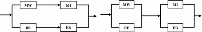
Simplified diagrams of subsystems 1 and 2, left in case of failure in SC member, right in case of stable state in SC member

-
B)
If the SC member remains stable with full reliable condition (R = 1), the system may be simplified as in Fig. 10 (right):
In this case, the system reliability will be obtained as:
-
System A (left) having two parallel subsystems; therefore:
-
System B (right) having two parallel subsystems; therefore:
-
In the resulted system, two subsystems will be in series; therefore:
Now it can be seen that, previous complex system (combination of 1, 2 and 3 subsystems in Fig. 7) is separated into two simple subsystems and therefore the entire reliability may be written by combining the previous formulas. Therefore, Equations 3, 4, 8 and 12 results in the total reliability as:
To obtain the total reliability of tunnel support system, the results of the complex part of the block diagram in Fig. 8 (Eq. 14) should be combined with previous parts in Eqs. 1 and 2. The result will be like Eq. 15:
Case studies
In order to practically calculate the reliability of tunnel support system, a series of structural data of several tunnels in Iran is presented. This information was based on final design and calculation of these tunnels which has been done according to acceptable design codes. Three railway tunnels named by Aran, Doab and Khalenjeh were chosen for this study. These tunnels, specifications of which are shown in Table 1, are located in the western part of the country along the south-west block of Iranian Railway Network which at this date is still under construction. The railway line is a kind of one-way rail track which is passing through very severe topographical condition and highly mountainous zone (Hexa CE 2010).
Reliability estimation for the individual components
So far it is shown how the reliability of the whole tunnel structure is dependent on the individual reliabilities for its components. In order to determine the final reliability of the tunnel support system, the estimated values of isolated reliabilities for the incorporated elements should be specified. In this research a practical method has been utilized based on determination of isolated reliabilities. The general procedure applied in this paper for calculation of reliability for individual components and the whole system is shown in Fig. 11. The procedure is described in the following sections.

General procedure for calculation of isolated reliabilities and final reliability for the tunnel structure
Finite element modeling
Using the procedure shown in Fig. 11, it is necessary to make enough finite element models for different components of the tunnel support system to obtain design safety factors corresponding to the particular elements. Employed FE models are briefly addressed in Table 2. As it is indicated in the table due to the complex behavior, no finite element model is considered for the components MI and CB. Therefore, the reliability of these components is considered as R = 1 for the case studies. However, the whole model is flexible to apply any quantity for these elements once any method for their isolated calculation is recognized in the future. The rest of components are modeled using suitable FE models as shown in the table.
Determination of isolated safety factors
As the general definition, the safety factor parameter for design of various elements in the tunnel support system can be extracted by this Equation:
in which and are resistance strength and stress level in the elements. By applying several structural calculations and calculating the amount of pressure in the support elements and estimating their maximum resistance capacities, it is possible to determine the isolated safety factors for the different elements. Using this method the FS values have been determined for all of the tunnel support components for the case studies (except MI and CB elements). In order to demonstrate the general procedure of this calculation, several examples for one of the case studies (Doab Tunnel) are presented in Table 3. The same procedure employed for the other cases.
Define two lower and upper band scenarios
The initial specifications in the Table 2 are regarded as the basic scenario (called as scenario D3) for tunnel support structure. These characteristics are obtained precisely according to the final as-built drawings of the selected case studies. This process indicates that for the basic scenario the consultant engineering company (Hexa CE 2010), has calculated the chosen tunnels and the initially employed assumptions are acceptable for the reliability calculations.
In order to observe the overall performance of existing design scheme of the consultant engineers (according to the basic scenario in the selected case studies) from reliability engineering point of view, hypothetical assumptions of the tunnels are exposed to some variations. Variation in the given specifications will normally change the results of reliability analysis. Hence the calculation process of safety factors and reliability values will be modified base on new presumptions. This modification will also provide a sense of probabilistic estimation about the reliability characteristic of tunnel by different employed specifications. Owing to this end two new scenarios called as scenarios D1, D2 are defined with higher and lower specific properties relatively rather than the basic scenario. This means that the generalized quality and properties of the tunnel support components are modified both into the higher and lower values to examine the their effects on reliability parameters.
These scenarios (D1, D2) have been regarded as the excessive alternatives by following configurations:
-
Scenarios D1: Approximately 20 % improvement in the dimensions/arrangement of tunnel support elements.
-
Scenarios D2: Approximately 20 % decline in the dimensions/arrangement of tunnel support elements.
These scenarios can basically be considered as the upper and lower cases relative to the basic scenario. The values of ±20 % are just selected as the tentative examinations for accomplishing sensitivity analysis and observing the changes in reliability.
Ground specifications and material properties are selected the same as basic scenario. The estimated geometries and arrangement of structural elements corresponding to the three scenarios D1, D2 and D3 presented in Table 4.
Using the same procedure of Table 3, the safety factor quantities are computed for the new scenarios (D1, D2) in different structural elements (BE, EB,…). It should be emphasized that, once the FS is being calculated for these cases in any part of the tunnel support system, the load and resistance conditions for the new scenarios (D1, D2) are employed. The values of safety factors are calculated for seven structural components (BE, EB, Mw, SC, KB, CE, CJ), three case studies (Aran, Doab, Khalenjeh) and three scenarios (D1, D2, D3), so then the total number of 63 values are totally obtained. The result of these calculations is reported in Table 5.
Determination of isolated reliability values
Once the safety factors are determined in the last section, the reliability values can be linearly correlated to the FS quantities. As surveyed in the relevant literature, the reliability of components can be correlated to their design safety factors. This is because the reliability parameter will normally be increased by raising the design safety factors correspondingly. As an example in the field, Ayyub and White (1987) obtained the load and resistance factor design (LRFD) for structural systems under conditions of uncertainty and probabilistic analyses. Partial safety factors were determined by them to account for the uncertainties in strength and load effects. Manners (1989) in another work used reliability analysis techniques to evaluate safety factors for structural design codes and made some suggestions for improving the acceptability of reliability-based safety factor. Taking the advantages of inverse measures into account Elishakoff (2001) correlated probability performance measure and probability sufficiency factor (safety factor) for design of structures. Extension of optimum safety factor method to reliability-based design optimization was also reported by Kharmanda and Olhoff (2007) to demonstrate the efficiency of their reliability-based safety factors. Considering the idea of linear correlation between safety factor and reliability parameter, it is possible to use following equation for this study:
In which R and F.S are the reliability and safety factor values for any structural element in the tunnel support system and c is the constant coefficient of linear correlation. Considering R = 1 as the highest value of reliability corresponding to the maximum possible safety factor which is obtained in Table 5, the coefficient c can be determined as following:
The coefficient c is obtained by indication of 10 decimal numbers in order to find the precise values of reliability for the individual elements. By applying this constant value (c = 0.4732612399) for different tunnel support elements, the maximum value of reliability is calculated as (R = 0.999999999) for the case of Aran tunnel, scenario D1, element SFMW. By applying this constant transformer to other range of FS values in Table 5, the reliability quantities are determined as indicated in Table 6.
Determination of final reliabilities by decomposition method
As described before, the final reliability of the system is written as a mathematical equation (Eq. 16) relevant to isolated reliabilities of the components. The results of reliability estimation for structural components achieved in previous sections were employed to estimate the final reliability for the whole system. Owing to this end, using the procedure of Fig. 11 and applying Eq. 16 (calculation of reliability with decomposition method), values of reliabilities were calculated and presented in Table 7. The values of this table are computed according to the component’s reliabilities and their equations of relation to reach the entire reliability of the system. The total values of reliability are presented in the last column of this table as RSYS.
Discussion
The diagrams of correlations between reliability and safety factor values are discussed in this section. Then the results of the reliability analyses for different levels of calculations are compared to the each other to see the variation mechanism of reliability in different subsystems. Finally, an estimation of average time to failure is presented in the following subsections.
Correlation between FS and R
To demonstrate the correlation between FS values and reliability quantities, the results of calculations for individual components are depicted simultaneously in Fig. 12. Only the results of calculation for structural components SC, BE, KB and SE are reported in this figure as the samples for presentation. Results of other components also follow the similar pattern. The figure contains the results of FS and R parameters for three case studies and three scenarios.

a–d Isolated FS and reliability values for the tunnel support elements for several samples (SC, BE, KB, SE)
Variations in reliability and safety factors in Fig. 12 indicate that for all of the cases, corresponding values of the basic design scenario (D3) are located in the middle range of the relevant values for other two scenarios (D1 and D2). This means that the negative and positive changes in the configuration of structural elements in tunnel support system have had similar influences on the parameters FS and R. It addition, both FS and R values are coherently altered with the parallel trend towards the variations in design specifications.
Variation in isolated reliabilities
Corresponding results of reliability calculation for isolated tunnel components are depicted together in Fig. 13. This figure contains the results of reliability calculations totally for 63 cases (seven structural components, three case studies and three scenarios).

Isolated reliability values for the tunnel support elements. a Aran, b Doab, c Khalenjeh
Based on the ranges of variation in reliability parameters in Fig. 13, the level of reliability for tunnel components can be observed in the case studies. Components with better reliability outputs are additionally visible from the results. From the general view point, calculated reliability values in the components of Aran and Khalenjeh tunnels have demonstrated nearer output trends in which the MW elements have offered the maximum R values. This element conversely has been among the worst in the case of Doab tunnel. SE element in Khalenjeh tunnel reported to have the minimum reliability value, whereas corresponding values in the two other tunnels have been in a more acceptable range. It is also noticeable that KB element in all three case studies has been demonstrated among the elements with least R values.
Histogram of calculated individual safety factors
To roughly assess the probability distribution of the obtained values of isolated safety factors, Fig. 14 depicts the frequencies of observations occurring in certain ranges of the values. Owing to this end, the results of FS calculations for structural components of three tunnels (case studies) are combined together and the histograms and normal distribution functions fitted for variation of FS values in D1, D2 and D3 scenarios are reported in this figure.

a–c Histograms and Normal distribution fitting for variation of design safety factors in D1, D2 and D3 scenarios
Reliability in various decomposition levels
Figure 15 shows the results of reliability calculations in different levels of decomposition based on Fig. 7. This suggests the variation of the adopted reliability model for the development of the final reliability in different components. The range of reliability variations for the subsystems “t”, “4” and “5” are separately presented in this figure. Subsystem “t” accounts for the total reliability of the components SC, RB, and WM in Fig. 7. Subsystems “4” and “5” also account for the integrated components in concrete lining and steel frame, respectively.

a–d The range of reliability variations for the subsystems “t”, “4” and “5” and the entire system
According to Fig. 15, variation graph of the final reliability (Fig. 15d) is more identical to the corresponding variations in the subsystems 4 and 5. (Fig. 15b, c). Despite these similar patterns, the overall variation of reliabilities for subsystem “t” according to the Fig. 15a, is more different rather than other three graphs. In other word, the final reliability parameter demonstrates a closer trend with results of reliability for steel frames and concrete lining, in spite of relatively large difference rather than subsystem t (combination of rock bolt, shotcrete and steel mesh). This pattern is observed almost in all case studies and shows that the reliability of tunnel support system has mainly affected by steel frames and concrete lining rather than other components.
In addition, it can be seen from Fig. 15 that for the selected case studies, the calculated values of reliabilities for combination set of rock bolt, shotcrete and steel mesh elements have considerably demonstrated lower variations as the entire quantities have been between 0.98 and 1. However, the amount of variations for other subsystems has been significantly higher. By the way the results are highly sensitive to the adopted assumptions for tunnel structure and cannot be considered as the proven hypotheses until future validations.
Estimation of MTTF based on reliability
So far the general procedure is presented to derive the reliability of tunnel structure based on the structural safety factors in components. There are some other parameters which may be calculated based on system reliability. The most common reliability parameter is the mean time to failure (MTTF), which can also be specified as the failure rate of the system. MTTF is a basic measure of reliability for non-repairable systems. It is the mean time expected until the first failure of a piece of equipment. MTTF is a statistical value and is intended to be the mean over a long period of time and with a large number of units (Xu and Rahman 2005). For constant failure rate systems, MTTF is the inverse of the failure rate parameter. Provided that the anticipated time of operation for tunnel is known the MTTF value can be determined. As an example in this study, the anticipated operation time is estimated as 25 years for the case studies. So the method for calculation of MTTF is presented as follows:
in which λ is the constant failure rate per unit year, applied in constant failure rate (CFR) function. Therefore, the mean time expected to failure for each of the tunnel systems in this study can be computed by:
These parameters calculated for three tunnels and scenarios as shown in Table 8. As an example, in the case of Aran-D3 scenario, if the operation time is assumed to be 25 years, with the probability of 86.52 percent for the tunnel support system, the failure rate per year will be equal to 0.0072.
The results of MTTF calculations for different tunnels and scenarios are demonstrated in Fig. 16. By looking at this figure it can be remarked that as a result of exponential function, the values of MTTF parameters are significantly changed with a highly notable trend rather than reliability parameter. For instance, in case of Doab tunnel, a specific increase in reliability values from 95.7257 to 98.9296, (Doab-D3 to Doab-D1) has led to a remarkable increase in MTTF from 458 to 1,858 years.

Calculated results of MTTF parameter for selected tunnels in different scenarios
Conclusions
Although studying the statistical methods of evaluating the reliability of the tunnel structural support system is a very complicated subject and is still in the infancy stage, the present paper examined the issue by using an analytical procedure and probabilistic evaluation.
First of all, various components of tunnel support system were identified in order to discuss the overall safety concerns for a tunnel structure. Various components of structural system for the tunnels which are excavated in jointed rocks with weak ground condition were categorized and incorporating elements were specified. Then the performance relationships between these components were determined. In this context, components of the tunnel were introduced and their behavior described with concentration on their reliabilities. Then, the block diagram of reliability for the system was summarized based on different elements. In this diagram all of components subsystems were connected using serial and parallel connectors elements based on success and failure paths in the system. In addition to simple connectors, the block diagram also consisted of a complex part.
After recognizing the relations between the tunnel support components and completing the block diagram, the reliability of the entire system was calculated. For these purposes, the decomposition method was established as an analytical solution. The overall reliability of the system was connected to isolated reliabilities of individual components of the system.
Then, in order to practically understand the problem and calculate the reliability with physical values, three series of data were gathered about three tunnels in Iranian Railway Network called Aran, Doab and Khalenjeh from which the reliability quantities were obtained.
Since the overall system reliability assessment depends on the reliability of each component in these methods, an important part of the article was dedicated in order to estimate the method of assigning the reliability values to each component of structural system of the tunnel.
Considering the idea of linear correlation between safety factor and reliability parameter, first the individual safety factors for all of the components of the system were calculated and then they were connected to their reliabilities. Owing to this end, several finite element models for different components of the tunnel support system were prepared to obtain design safety factors corresponding to the particular elements. By applying several structural calculations and computing the amount of pressure in the support elements and estimating their maximum resistance capacities, the isolated safety factors for the different elements were found out. Using this method the FS values were determined for all of components for the case studies.
In order to observe the overall performance of existing design scheme of the consultant engineers (according to the basic scenario in the selected case studies) from reliability engineering point of view, hypothetical assumptions of the tunnels were exposed to two upper and lower band levels for the case studies.
In the next step the safety factors were computed for the scenarios (D1, D2, D3) in different structural elements (BE, EB,…) and for three case studies. Once the safety factors were determined, the reliability values were linearly correlated to the FS quantities. By applying a constant transformer to all range of FS values, the reliability quantities were determined for all components of the system. Finally, by applying the mathematical equations of decomposition method, the final values of reliabilities were calculated for the entire tunnel structures. The major results of this study and the tasks for the future are as the following:
-
1.
The proposed reliability evaluation method of tunnel support system built in this study is effective not only for investigating the reliability of individual elements in the structure but also for building an overall methodology to calculate the reliability performance of the entire tunnel structure.
-
2.
The correlation method to calculate reliability values based on isolated safety factors in this study demonstrated reasonable trends in ranges of parameter variations for different components. Variations in reliability and safety factors demonstrated that for all of the cases, corresponding values of the basic design scenario (D3) are located in the middle range of the relevant values for other two scenarios (D1 and D2). This means that the change in configuration of structural elements in tunnel system have had similar influences on the parameters FS and R. It addition, both FS and R values are coherently altered with the parallel trend towards the variations in design specifications.
-
3.
Methodology of reliability evaluation for individual components which is presented in this article is able to report the R parameter for different components of the system and give estimation about the level of R in different elements. For instance calculated reliability values in the components of tunnels for case studies indicated that the tunnel lining subsystem (KB element) in all three case studies has been demonstrated among the elements with least R values.
-
4.
Combining the results of isolated reliabilities for the case studies in terms of histograms demonstrated an acceptable agreement between the obtained data and fitted normal distribution functions.
-
5.
The method of reliability evaluation for the entire system can report appropriate estimations about the effective weight of different elements in the final reliability of the system. Results of the case examples demonstrated that the final reliability value in all tunnels has had more identical trend with respect to the results of reliability for steel frames and concrete lining, in spite of relatively large difference rather than other subsystems including of rock bolt, shotcrete and steel mesh. This pattern is observed almost in all case studies and shows that the reliability of tunnel support system has been mainly affected by steel frames and concrete lining rather than by other components. Incidentally, the results are highly sensitive to the adopted assumptions for tunnel structures and cannot be considered as the proven hypotheses until future validations.
-
6.
The method is able to offer proper estimation about the parameter of MTTF for the tunnel structure. As a result of exponential function, the values of MTTF parameters in the case studies were significantly changed with a notable trend rather than reliability parameter.
In a back analysis, to select the minimum failure time based on the importance of the tunnel, reliability of the tunnel structure can be changed by changing the individual reliabilities and initial assumptions including the type and characteristics of various members of the support system. In other words, by changing the type of support elements, a desirable reliability and, therefore, an appropriate failure time can be anticipated. This idea is an anticipated field of research for further investigations by the authors. Recognition of suitable approaches for validation of the proposed methodologies is also another field for our future studies.
References
Ayyub BM, White AM (1987) Reliability-conditioned partial safety factors. J Struct Eng 113(2): 280–283 (ASCE)
Baecher GB, Christian JT (2003) Reliability and statistics in geotechnical engineering. Wiley, West Sussex
Cai GQ, Elishakoff I (1994) Refined second-order reliability analysis. Struct Saf 14(4):267–276
Celestino TB et al (2006) Evaluation of tunnel support structure reliability. Tunn Undergr Space Technol 21:311–322
Dai SH, Wang M (1992) Reliability analysis in engineering applications. Van Nostrand Reinhold, New York
Dehghan AN, Shafiee SM, Rezaei F (2012) 3-D stability analysis and design of the primary support of Karaj metro tunnel: based on convergence data and back analysis algorithm. Eng Geol 141–142(19):141–149
Duncan JM (2000) Factors of safety and reliability in geotechnical engineering. J Geotech Geoenviron Eng 126(4):307–316
Ebeling CE (1997) An introduction to reliability and maintainability engineering. McGraw-Hill Companies Inc, Boston
Elishakoff I (2001) Interrelation between safety factors and reliability. NASA Report CR-2001-211309
Federal Highway Administration (FHWA) (2005) Road Tunnel Design Guidelines. In: FHWA-IF-05-023, National Highway Institute, U.S. Department of Transportation, Washington, D.C. USA
Federal Highway Administration (FHWA) (2009) Technical manual for design and construction of road tunnels—civil elements. In: Hung CJ et al (ed) FHWA-NHI-10-034. National Highway Institute, U.S. Department of Transportation, Washington, D.C. USA
Frangopol DM, Strauss A, Bergmeister K (2009) Lifetime cost optimization of structures by a combined condition—reliability approach. J Eng Struct 31(7):1572–1580
Gharouni-Nik M, Naeimi M (2009) Determining the reliability of tunnel support system using decomposition method and minimal cut-path approach. In: Proceeding of 8th Iranian Tunnelling Conference, Tehran, Iran
Hexa Consulting Engineers Company (2010) Structural calculation leaflets for west railway tunnels, Aran, Doab, Khalenjeh. Client: Iran ministry of road and urban development
Hoek E (1998) Reliability of Hoek-Brown estimates of rock mass properties and their impact on design. Int J Rock Mech Min Sci 35(1):63–69
Holicky M (2009) Probabilistic risk optimization of road tunnels. Struct Saf 31(3):260–266
Kaveh A, Kalat VR (1995) Reliability theory and its application in structural engineering. Iran University of Science & Technology, published in Persian
Kececioglu D (1991) Reliability engineering handbook. Prentice-Hall, Englewood Cliffs
Kharmanda G, Olhoff N (2007) Extension of optimum safety factor method to nonlinear reliability-based design optimization. Struct Multidiscip Optim 34:367–380
Kitamura T, Kojo H (1998) Influence and control of adjacent blasting on the safety of tunnel linings—an estimation of safety based on the reliability theory and some applications. Int J Rock Mech Min Sci Geomech 25(3):147
Kohno S, Ang AH-S, Tang WH (1992) Reliability evaluation of idealized tunnel system. Struct Saf Reliab 11:81–93
Kuesel TR, King EH, Bickel JO (2004) Tunnel Engineering Handbook. Kluwer Academic publisher, The Netherlands, ISBN-10: 1461380537
Langford JC, Diederichs MS (2013) Reliability based approach to tunnel lining design using a modified point estimate method. Int J Rock Mech Min Sci 60:263–276
Laso E, Sagrario Gemez M, Alarcon E (1995) A level II reliability approach to tunnel support design. Appl Math Model 19:372–382
Li HZ, Low BK (2010) Reliability analysis of circular tunnel under hydrostatic stress field. Comput Geotechnics 37:50–58
Low BK, Tang WH (1997) Efficient reliability evaluation using spreadsheet. J Eng Mech 123(7):749–752
Lu Q, Low BK (2011) Probabilistic analysis of underground rock excavations using response surface method and SORM. Comput Geotech 38(8):1008–1021
Lu Q, Sun HY, Low BK (2011) Reliability analysis of ground–support interaction in circular tunnels using the response surface method. Int J Rock Mech Min Sci 48(8):1329–1343
Lu Q, Chan CL, Low BK (2013) System reliability assessment for a rock tunnel with multiple failure modes. Rock Mech Rock Eng 46:821–833
Manners W (1989) Improving the acceptability of reliability-based safety factors for the design of structural systems. Reliability and optimization of structural systems’88. In: Lecture Notes in Engineering, vol 48, pp 173–189
Mollon G, Dias D, Soubra AH (2009a) Probabilistic analysis and design of circular tunnels against face stability. Int J Geomech 9(6):237–249
Mollon G, Dias D, Soubra AH (2009b) Probabilistic analysis of circular tunnels in homogeneous soil using response surface methodology. J Geotech Geoenviron Eng 135(9):1314–1325
Oreste P (2005) A probabilistic design approach for tunnel supports. Comput Geotech 32:520–534
Rasouli M (2009) Engineering geological studies of the diversion tunnel, focusing on stabilization analysis and support design. Eng Geol 108(3–4, 8):208–224
Schweiger HF, Thurner R, Pöttler R (2001) Reliability analysis in geotechnics with deterministic finite elements. Int J Geomech 1(4):389–413
Shin H, Kwon Y, Jung Y, Bae G, Geun Y (2009) Methodology for quantitative hazard assessment for tunnel collapses based on case histories in Korea. Int J Rock Mech 46(6):1072–1087
Simpson B (2011) Reliability in geotechnical design—some fundamentals. In: Proceeding of Third international symposium on geotechnical safety and risk, vol 1. Bundesanstalt für Wasserbau, Munich, pp 393–399
Tsai CW, Franceschini S (2005) Evaluation of probabilistic point estimate methods in uncertainty analysis for environmental engineering applications. J Environ Eng 131(3):387–395
Xu B, Low BK (2006) Probabilistic stability analyses of embankments based on finite-element method. J Geotech Geoenviron Eng 132(11):1444–1454
Xu H, Rahman S (2005) Decomposition methods for structural reliability analysis. Probab Eng Mech 20:239–250
Yang CY, Zhang M (1999) Reliability-based design method for cut-and-cover tunnels. Chin J Rock Mech Eng 18-1:40–45
Yang CY, Xu MX, Chen WF (2007) Reliability analysis of shotcrete lining during tunnel construction. J Constr Eng Manag 133:975–981
You K, Park Y, Lee JS (2005) Risk analysis for determination of a tunnel support pattern. Tunn Undergr Space Technol 20:479–486
Acknowledgments
We express our gratitude to Iranian Tunnelling Association (IRTA) and Hexa Consulting Engineers Company for their supportive cooperation specially by providing accessibility to structural calculation leaflets for the case studies. This research was undertaken in the School of Railway Engineering, Iran University of Science and Technology (IUST).
Conflict of interest
The authors declare that they have no competing interests.
Authors’ contributions
MGN was the supervisor of this research program and defined the main theme and objective of the study for MN. MGN guided the research process and was involved in language editing and finalizing the manuscript writing. As the corresponding author, MN implemented the research methodology, obtained calculation results, processed the outputs and established the structure of this article. The first draft of the paper was also prepared by MN. SA and ZA accompanied MGN and MN for the application of reliability engineering and probabilistic evaluation together with the structural calculations in this research. All authors read and approved the final manuscript.
Author information
Authors and Affiliations
Corresponding author
Rights and permissions
Open Access This article is distributed under the terms of the Creative Commons Attribution License which permits any use, distribution, and reproduction in any medium, provided the original author(s) and the source are credited.
About this article

Cite this article
Gharouni-Nik, M., Naeimi, M., Ahadi, S. et al. Reliability analysis of idealized tunnel support system using probability-based methods with case studies. Int J Adv Struct Eng 6, 1 (2014). https://doi.org/10.1007/s40091-014-0053-6
Received:
Accepted:
Published:
DOI: https://doi.org/10.1007/s40091-014-0053-6