
Abstract
In this paper, whether the coal fines can be induced by shear failure during drainage process has been discussed in detail. By coupling with the percolation theory, the elasticity mechanics were used to construe the extra stresses in the formation surrounding with the hydraulic fracture. The safe window of the bottom hole pressure was also calculated from the failure envelope. The research shows that the formation pressure on the fracture surface of the coal seam is negatively related with the bottom hole pressure, and the induced stress is positively related with the bottom hole pressure during the drainage process of fractured CBM wells. The pore pressure around the fracture changed due to pore-elastic effects, which also caused a significant change of the in situ stresses. In order to avoid the breakout of the coal seam around hydraulic fracture during drainage process, the model of the reasonable bottom hole pressure is also built.
Introduction
The coalbed methane (CBM) resources in China are abundant, and the exploration and development of CBM in China also have made great achievements; what is more, the CBM has achieved commercial exploitation and development.
During the operation of CBM wells, coal fines are easily generated due to the rise of liquid level or pressure changes (Liu et al. 2012a, b; Zhang et al. 2009). The coal fines clog gas production channels of CBM wells, which can reduce the production of CBM wells even after they are put into operation. It is difficult to keep the production of CBM wells stable, and it also hard to maintain high yield, which affects the overall development of CBM benefits. Coal fines are among the key issues that restrict the highly efficient production of CBM, because they cause blockages in reservoirs and accidents in wellbores. With the CBM producing gas, it also produces different extent of coal fines, especially hydraulic fractured well.
Wei et al. (2013) points out that coal fines production results from unreasonable drainage operation parameters, such as unreasonable bottom hole pressure and drainage quantity (Wei et al. 2013). Some researchers (Chen et al. 2009; Marcinew and Hinkel 1990; Zhang et al. 2012) argue that coal fines unload and gather in the bottom of the well, which results in pipe blockage and getting stuck. The continuity of gas and water flow is broken off, and correspondingly, the gas production declines quickly (Chen et al. 2009; Marcinew and Hinkel 1990; Zhang et al. 2012). Furthermore, the cost of developing CBM increases significantly by several times of checking pump operation. At present, researchers ( Wang et al. 2011, 2013) focus on the evaluation of the wellbore stability of CBM wells (Wang et al. 2011, 2013; Soliman et al. 2004). And what is important, the possibility of shear failure mechanisms induced by fractures is not clear during the coal fines production. Hydraulic fracturing can produce induced stress and result in the formation pressure declination in the coal seam, which leads to the redistribution of the in situ stress field near the fractures. For the induced stress, it can be obtained by RFPA 2D flow method, traditional FEM method, and cohesive interface method for modeling fractures (Olson and Wu 2012; Liu and Ai 2015; Guo et al. 2015). According to the elasticity mechanics coupled with percolation theory, the analytical model of stress field for fractured coal seam can be derived. The stability of fractures surface can be evaluated by the instability criterion, which is good to determine reasonable bottom hole pressure and hinders coal fines production.
Analytical model of stress field
According to the study of Sneddon (1946), it is assumed that the fracture is vertical in homogeneous and isotropic reservoir, with the height of \( H \) and elliptical longitudinal profile. The 2D geometry model for fracture is shown in Fig. 1 (Sneddon and Elliot 1946; Sneddon 1946).

Geometry for 2D fracture
A coordinate system is established, that is, the fracture length, fracture width, and fracture height are x, y, and z coordinate directions, respectively. Fractures extend perpendicular to minimum horizontal principal stress direction. Therefore, the x, y, and z coordinate directions are the directions of the minimum horizontal principal stress direction, the maximum horizontal principal stress, and the vertical direction.
Warpinski and Branagan (1989) suggests that the total stress is equal to induced stress plus in situ stress adopting the principle of superposition. The induced stress is produced by different mechanisms. Hydraulic fracturing, pore elasticity effect, and gas desorption can lead to induced stress (Wright et al. 1995).
where \( \sigma_{{}} \) is total stress during CBM gas production, MPa; \( \sigma_{0} \) is in situ stress, MPa; \( \Delta \sigma_{\text{F}} \), \( \Delta \sigma_{\text{b}} \) and \( \Delta \sigma_{\text{L}} \) are induced stresses from hydraulic fracturing, pore elasticity effect, and gas desorption, respectively, MPa.
The total stress can be divided into x, y, and z coordinate direction, that is
where \( \sigma_{x} \), \( \sigma_{y} \), and \( \sigma_{z} \) are stresses of x, y, and z coordinate direction, respectively, MPa; \( \sigma_{x0} \), \( \sigma_{y0} \), and \( \sigma_{z0} \) are in situ stress along x, y, and z coordinate direction, respectively, MPa; \( \Delta \sigma_{{{\text{F}}x}} \), \( \Delta \sigma_{{{\text{F}}y}} \), and \( \Delta \sigma_{{{\text{F}}z}} \) are induced stress from hydraulic fracturing along x, y, and z coordinate direction, respectively, MPa.
Stress Induced by hydraulic fracturing
Wright et al. (1995) identifies that fractures can alter the value and direction of stress near the wellbore area by adopting re-fracturing operation in the field (Wright et al. 1995). Warpinski and Branagan (1989) derives the formula of calculating induced stress at arbitrary point A, which is based on the geometry model shown in Fig. 1. The formula can be simplified as (Warpinski and Branagan 1989):
The parameters in Eqs. 5–7 can be calculated by the following equations.
where \( p_{i} \) is net pressure on the fracture surface, MPa; \( c \) is half of the fracture height, that is \( {H \mathord{\left/ {\vphantom {H 2}} \right. \kern-0pt} 2} \), m; \( r \) is the distance between the center point of the fracture and the point A, m; \( r_{1} \) is the distance between the lower end point of the fracture and the point A, m; \( r_{2} \) is the distance between the upper end point of the fracture and the point A, m; \( \theta \) is the angle between the Z axis and the line through both the center point of the fracture and the point A, \( ^\circ \); \( \theta_{1} \) is the angle between the Z axis and the line through the lower end point of the fracture and the point A, \( ^\circ \); \( \theta_{2} \) is the angle between the Z axis and the line through both the upper end point of the fracture and the point A, \( ^\circ \); \( p_{wf} \) is the bottom hole pressure in the hydraulic fractures, MPa; \( \sigma_{h} \) is the closure pressure of fractures (that is the minimum principal in situ stress), MPa; \( \Delta \tau_{{{\text{F}}xz}} \) is shear stress at point A in X–Z plane, MPa.
If \( \theta \), \( \theta_{1} \), and \( \theta_{2} \) are all negative, then they can be replaced by \( \theta + \pi \), \( \theta_{1} + \pi \), and \( \theta_{2} + \pi \) correspondingly. The induced stress along the direction of fracture length can be calculated by Hooke’s law.
where \( v \) is Poisson’s ratio.
According to Eqs. 5–7 and 15, when the bottom hole pressure \( p_{wf} \) decreases, the absolute value of the net pressure on the fracture surface \( p_{i} \) will increase, which results in larger induced stress. Therefore, the induced stress of seam fractures is positively correlated with the net pressure on the fracture surface \( p_{i} \) and negatively correlated with the bottom hole pressure \( p_{wf} \).
In this section, an actual coal seam with log data and fracturing data is chosen to study the relationship between the induced stress and the bottom hole pressure. The necessary parameters are shown in Table 1.
First, according to Eqs. 5–7, the stress near the wellbore area can be obtained.
Second, keeping the above three parameters of \( \Delta \sigma_{{{\text{F}}x}} \), \( \Delta \sigma_{{{\text{F}}z}} \), and \( \Delta \tau_{{{\text{F}}xz}} \) as constant and decreasing the bottom hole pressure, the net pressure can be obtained by using the following formula.
where \( \alpha \) is the correction factor.
Finally, the induced stress of seam fractures can be calculated according to Eq. 15. The calculated results are shown in Fig. 2.

Calculating results
Figure 2 shows that the induced stress of seam fractures is positively correlated with the net pressure on the fracture surface, which also means that the induced stress of seam fractures is negatively correlated with the bottom hole pressure.
Decreasing formation pressure induces stress
\( \Delta \sigma_{\text{b}} \) and \( \Delta \sigma_{\text{L}} \) are induced when the formation pressure decreases in Eq. 1, so the total induced stress is the sum of the two,
where \( \Delta \sigma_{\text{p}} \) is the total induced stress when formation pressure decreases.
Therefore, Eq. 1 is rewritten as:
when the CBM produces gas in the principle of constant bottom hole pressure \( p_{wf} \), then \( \sigma_{ 0} \) and \( \Delta \sigma_{\text{F}} \) remain constant, so the change of total stress is only the total induced stress \( \Delta \sigma_{\text{p}} \) dependent
where \( \Delta \sigma \) is the change of total stress during gas production, MPa.
Stress induced by pore elasticity effect
During the gas production, the percolation of the CBM fracturing well is simplified as a single-phase linear flow in the homogeneous coal seam which is defined by a semi-infinite domain (\( 0 \le x \le \infty \)). The formation pressure near the fractures changes with time, which leads to the redistribution of the stress near fractures.
It is assumed that coal seam is considered as isotropic homogeneous media, and its initial pressure is \( p_{0} \), and the bottom hole pressure is \( p_{wf} \). The stress induced by the pore elasticity effect can be written as:
where \( \Delta \sigma_{\text{b}} \) is the induced stress of pore elasticity effect, MPa; \( P \) is the formation pressure with the distance of \( x \) away from the fracture surface at time \( t \);\( \alpha \) is Biot pore elasticity coefficient.
In particular, the formation pressure is equal to the bottom hole pressure on the fracture surface.
Stress induced by desorption
When the formation pressure decreases to the critical desorption pressure, then the methane desorbs with coal matrix shrinkage simultaneously. Barenblatt et al. (1960) and Espinoza (2013) did certain experiments about the study of coal matrix shrinkage and swelling. They demonstrate that coal matrix shrinkage and swelling have an effect on induced stress (Zhang et al. 2012; Wang et al. 2013).
There are many methods to calculate the induced stress from coal matrix shrinkage and swelling. It is assumed that the CBM desorption starts at the initial formation pressure. According to the S-D adsorption and stress calculation method (Pascal et al. 1981) (Zhang et al. 2012), the volumetric strain caused by desorption of CBM can be written as:
where \( \Delta \varepsilon_{\text{s}} \) is strain caused by gas desorption (or adsorption); \( \varepsilon_{{\text{smax} }} \) is strain of the maximum coal matrix shrinkage; \( p \) is the formation pressure, MPa;\( p_{\varepsilon } \) is the formation pressure when the strain is half of the maximum coal matrix shrinkage, MPa.
The change of stress caused by desorption of CBM can be written as:
where \( \Delta \sigma_{L} \) is induced stress by desorption of CBM, MPa; \( E \) is the Young’s modulus, MPa.
Total induced stress caused by decreasing formation pressure
According to the relationship between the initial pressure \( p_{0} \) and the critical desorption pressure \( p_{\text{c}} \), the total induced stress caused by the change of the formation pressure can be discussed as the following three cases.
-
1.
When \( p_{0} > p_{\text{c}} > p \), the water of the coal seam flows to the well without CBM desorption, then only the pore elasticity effect term is taken into consideration, that is
$$ \Delta \sigma_{\text{P}} = \left( {p_{{}} - p_{0} } \right)\alpha \frac{1 - 2\upsilon }{1 - \upsilon } $$(23) -
2.
When \( p_{0} > p > p_{\text{c}} \), the water of the coal seam flows to the well with CBM desorption, and the CBM desorbs at the pressure of the critical desorption pressure \( p_{c} \), then the pore elasticity effect term and the desorption term are taken into consideration, that is
$$ \Delta \sigma_{\text{P}} = \left( {p - p_{0} } \right)\alpha \frac{1 - 2\upsilon }{1 - \upsilon } + \frac{{E\varepsilon_{{{\text{smax}} }} }}{3(1 - \upsilon )}\left( {\frac{p}{{p + p_{\varepsilon } }} - \frac{{p_{c} }}{{p_{c} + p_{\varepsilon } }}} \right) $$(24)where \( p_{c} \) is critical desorption pressure, MPa.
-
3.
When \( p > p_{0} > p_{\text{c}} \), the water of the coal seam flows to the well with CBM desorption, and the CBM desorbs at the pressure of the initial pressure \( p_{0} \), then the pore elasticity effect term and the desorption term are taken into consideration, that is
$$ \Delta \sigma_{\text{P}} = \left( {p - p_{0} } \right)\alpha \frac{1 - 2\upsilon }{1 - \upsilon } + \frac{{E\varepsilon_{{{\text{smax}} }} }}{3(1 - \upsilon )}\left( {\frac{p}{{p + p_{\varepsilon } }} - \frac{{p_{0} }}{{p_{0} + p_{\varepsilon } }}} \right). $$(25)
It is noted that if the formation pressure \( p \) is the bottom hole pressure \( p_{wf} \), then the induced stress of fractures surface can be calculated by substituting the formation pressure \( p \) into bottom hole pressure \( p_{wf} \) in Eqs. 23, 24, and 25. Figure 2 shows that the induced stress of seam fractures is negatively correlated with the bottom hole pressure, which means that if the formation pressure \( p \) is the bottom hole pressure \( p_{wf} \), the induced stress is negatively correlated with the formation pressure, that is to say, the greater the formation pressure decreases, the bigger the induced stress is.
The analysis method of critical parameters
In Eqs. 24 and 25, the parameters of \( \varepsilon_{{{\text{smax}} }} \) and \( p_{\varepsilon } \) are unknown, so a adsorption stress test needs to be performed to determine \( \varepsilon_{{{\text{smax}} }} \) and \( p_{\varepsilon } \). In the state of three-axis loading, it is very difficult to obtain the strain directly during the desorption process. However, the permeability is relatively easy to obtain. As the permeability is affected by the effective stress, we only need to obtain the changes of permeability during the desorption process, and then \( \varepsilon_{{{\text{smax}} }} \) and \( p_{\varepsilon } \) can be calculated.
In the analysis of stress sensitivity, the effective stress is frequently used. According to the definition of the effective stress, the formula can be written as:
where \( \sigma_{\text{e}} \) is the effective stress, MPa.
According to Eq. 26, \( \Delta \sigma_{\text{P}} \) can be obtained.
Substituting Eq. 27 into Eq. 24,
where \( \Delta \sigma_{\text{e}} \) is the change of the effective stress, MPa.
Substituting Eq. 27 into Eq. 25,
According to the definition of coal matrix compressibility coefficient, the relationship between natural fracture porosity and effective stress can be written as below (Cheng 2011).
where \( \phi \) is the porosity of coal matrix–fracture system, dimensionless; \( \phi_{0} \) is the porosity of coal matrix–fracture system under the initial conditions, dimensionless;\( C_{f} \) is volumetric compressibility coefficient of the coal matrix–fracture system, MPa−1.
The fracture permeability of coal seam can be written as below (Cheng 2011).
where \( K_{\infty } \) is the permeability of fractures, mD; \( b \) is the width of natural fractures, μm.
According to Eq. 31, we can rewrite it as shown below.
where \( K_{\infty 0} \) is the permeability of fracture at the initial formation pressure, mD; \( b_{0} \) is the width of coal fracture at the initial formation pressure, μm.
According to Eqs. 30 and 32, the relationship between the permeability and the effective stress can be written as below:
If the permeability of the coal is low (< 1mD), it should also be corrected by the slippage effect. Klinkenberg (1941) proposes that the relationship between gas permeability and rock permeability is (Liu and Ai 2015):
where \( K_{a} \) is the permeability of coal rock at the pressure \( p \) in gas medium, mD. \( b_{k} \) is the slippage coefficient under at the pressure \( p \).
The slip coefficient is critical to characterizing gas permeability in Eq. 34. When the permeability of coal rock is \( 0.0001\;{\text{mD}} < K_{a} < 1\;{\text{mD}} \), de Swaan (1976) proposes the empirical equation of the slip coefficient for low-permeability rocks (Guo et al. 2015):
In conclusion, the steps of data analysis of laboratory experiment are summarized as following:
-
1.
According to Eqs. 34 and 35, \( K_{\infty } \) can be calculated by the measured permeability \( K_{a} \) at different pressure.
-
2.
According to Eqs. 35 and 28, or 35 and 29, the values of permeability \( K_{\infty } \) at different gas pressure can be fitted by using the optimization algorithm. And then \( C_{f} \),\( \varepsilon_{{{\text{smax}} }} \), and \( p_{\varepsilon } \) are calculated consequently.
-
3.
According to Eqs. 24 or 25, the stress changes \( \Delta \sigma_{\text{p}} \) can be calculated at different pore pressure.
The criterion of fracture surface stability
The induced stress changes at each point near the fractures. Based on the above method, \( \sigma_{x} \), \( \sigma_{y} \), \( \sigma_{z} \), and \( \tau_{Fxz} \) of the point A near the fractures can be calculated. And then the principal stress of the point A can be calculated by the equation of the three-dimensional stress state (Wright et al. 1995)
where \( I_{1} \),\( I_{2} \), and \( I_{3} \) are the invariant of the first, second, and third stress tensors, respectively. Equation 36 is the equation of the stress state with three roots, that is \( \sigma_{1} \),\( \sigma_{2} \), and \( \sigma_{3} \) at the stress state of point A. The order of the three principal stresses is arranged from large to small according to their algebraic values, that is \( \sigma_{1} > \sigma_{2} > \sigma_{3} \).
Mohr–Coulomb theory describes the strength characteristics of geomaterials. However, the criterion ignores the effect of intermediate principal stress. The D-P criterion has high computational efficiency, and the effect of intermediate principal stresses is also taken into account. So the D–P criterion has been widely applied in rock mechanics.
In the D–P series criterion, there is a series of concentric circles on the π-plane. The first and the second invariant of effective stress partial tensor can be written as below.
where \( J_{1}^{{}} ,J_{ 2}^{{}} \) are the first and the second invariant of effective stress partial tensor, MPa2; \( \sigma_{ 1} ,\sigma_{ 2} ,\sigma_{ 3} \) is the principal stress, MPa.
According to the criterion of linear strength, the root-mean-square of shear strength is:
where \( J_{{ 2 {\text{s}}}}^{{}} \) is the shear strength, MPa2; \( C \) is the cohesion, MPa; \( \phi \) is the internal friction angle.
The analysis results of the previous section show that the bottom hole pressure \( p_{wf} \) is negatively correlated with the two induced stresses on the surface of the fractures. Therefore, a safety window of \( p_{wf} \) can be found. Only if the bottom hole pressure \( p_{wf} \) decreases to the critical value, that is \( J_{ 2}^{{}} \ge J_{{ 2 {\text{s}}}}^{{}} \), shear damage will occur on the surface of the fractures. By the way, in the CBM depletion development process, the bottom hole pressure cannot be too big, which must be smaller the original formation pressure.
Case study on analysis of fracture surface stability
Taking the coal seam of a certain block as an example, the average depth of coal seam is 650 m. The compressive strength and the tensile strength are 11.1 and 0.48 MPa, respectively. The Young modulus is 0.91GPa. The Poisson ratio and Biot pore elasticity coefficient are 0.31 and 0.69. The minimum and maximum horizontal principal stress are 11 MPa and 16 MPa. The vertical principal stress is 17.55 MPa. The initial pressure and the critical desorption pressure are 4.6 and 3 MPa. The gas desorption will occur until the pressure is less than 3 MPa. According to the results of well logging, the average height of fractures is 30 m, and the average porosity of coal seam is 4.3%, and the average permeability is 0.76 × 10⁻³ μm2. The internal friction angle is 32°.
Indoor experiment and analysis
The experiment of desorption and permeability for coal under three-dimensional stress conditions has been introduced in detail by Zhang et al. (2005), Jia et al. (2013) and Liu and Liu(2015). The steps are as follows:
-
1.
Choose or make standard coal sample with 5 cm × 5 cm × 10 cm (length × width × height);
-
2.
Put the coal sample into triaxial desorption–permeability test machine of the CBM. First, adjust the axial pressure to the set value, then adjust the surrounding pressure and pore pressure to the set value, finally, place the coal sample for 5 days to reach the absorption–desorption equilibrium, and measure the gas permeability of coal. The experimental setup is shown in Fig. 3.
Fig. 3 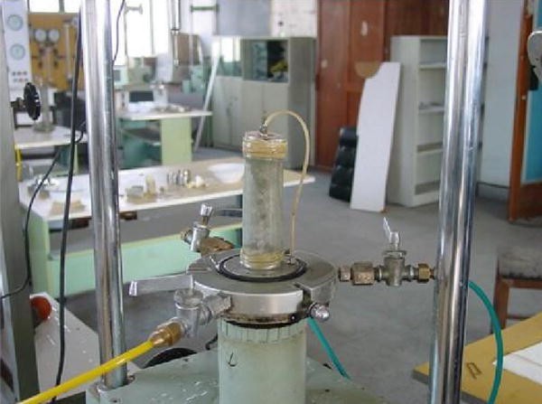
Experimental setup

This is a cycle test with the above two steps. In the process of testing, the coal sample remains intact in the testing machine. What needs to be done is to change the triaxial stress. By the way, the following test order and operating procedures should be obeyed. Firstly, when increasing the pore pressure, then the axial pressure also needs to be increased. Correspondingly, when decreasing the axial pressure, the pore pressure also needs to be decreased. Finally the condition of loading and unloading stress on coal sample can be simulated. The results of permeability test are shown in Fig. 4.

Results of permeability test
According to Eqs. 28 and 32, the following parameters can be obtained.
It should be noted that the optimization algorithm is used to fit the measured permeability at different pore pressure points.
The analysis of induced stress on the fracture surface
The height of fracture is 30 m, and the pressure inside fracture (pressure on the fracture surface) is 0.5, 1, 1.5, 2, 2.5, and 3 MPa, respectively. Two kinds of induced stresses are calculated, respectively,
-
1.
Stress induced by fractures
According to Eqs. 5, 6, 7, and 15, \( \Delta \sigma_{\text{Fy}} \), \( \Delta \sigma_{{{\text{F}}z}} \), \( \Delta \tau_{{{\text{F}}xz}} \), \( \Delta \sigma_{Fy} \) are calculated respectively. For example, when the bottom hole pressure is 1 MPa, the net pressure on the fracture surface \( P_{i} \) is − 10 MPa. Calculate the \( \Delta \sigma_{{{\text{F}}y}} \), \( \Delta \sigma_{{{\text{F}}z}} \), \( \Delta \tau_{{{\text{F}}xz}} \), and \( \Delta \sigma_{Fy} \), and divide them with the condition of \( P_{i} \). The fracture center is the origin point, and the value of each point is divided by 30 m, and the results are given on X coordinate, which is shown in Fig. 5.

Results of induced stresses along X axis
Figure 5 shows that the stress induced by the fractures of the coal seam is positively correlated with the net pressure on the fracture surface. The main effect area of the stress induced by the fractures is two times of fracture height in the minimum principal stress direction.
-
2.
Stress induced by formation pressure on the fracture surface
According to Eqs. 26–27, the induced stress on the fracture surface \( \Delta \sigma_{\text{P}} \), \( \Delta \sigma_{\text{b}} \), and \( \Delta \sigma_{\text{L}} \) can be calculated, which is shown in Fig. 6. Figure 6 shows that the smaller the bottom hole pressure is, the greater the formation pressure on the fracture surface of the coal seam decreases, and the greater the induced stress on the fracture surface is. The conclusion can be made that the formation pressure on the fracture surface of the coal seam is negatively related with the bottom hole pressure, and the induced stress is positively related with the bottom hole pressure.

Results of the stress induced by depletion of bottom hole pressure
Analysis of safety window of bottom hole pressure
After calculating the 3D stresses of \( \sigma_{x} \), \( \sigma_{y} \), and \( \sigma_{z} \) on the fracture surface and \( \tau_{{{\text{F}}xz}} \), the principal stress of \( \sigma_{1} \), \( \sigma_{2} \), and \( \sigma_{3} \) can be calculated by Eq. 22, respectively. The pressure inside fracture (pressure on the fracture surface) is set as 1, 1.5, 2, 2.5, and 3 MPa, respectively. The calculation results of the principal stress are shown in Fig. 7.

Calculation results of the principal stress
Being based on the principal of the D-P failure criterion and according to Eqs. 38–39, the second invariant of the effective stress \( J_{ 2}^{{}} \) and the root-mean-square of the shear strength \( J_{{2{\text{s}}}} \) can be obtained. The calculating results are shown in Fig. 8. Figure 8 shows that the second invariant of the effective stress \( J_{ 2}^{{}} \) is greater than the root-mean-square of the shear strength \( J_{{2{\text{s}}}} \) when the bottom hole pressure is less than 1.7 MPa. So the bottom hole pressure of the study area should be maintained above about 1.7 MPa, and it is also should be smaller than 4.6 MPa.

Calculating results of \( J_{ 2}^{{}} \) and \( J_{{2{\text{s}}}} \)
Conclusions
-
1.
Basing on the analytical model of stress field, shear damage on the fracture surface of coal is one of the important reasons of producing coal fines. Shear damage may result from the change of the in situ stress field during the drainage process of fractured CBM wells.
-
2.
After fracturing CBM well, the bottom pressure has a great effect on the two induced stress fields near the fracture surface. The formation pressure on the fracture surface of the coal seam is negatively related with the bottom hole pressure, and the induced stress is positively related with the bottom hole pressure during the drainage process of fractured CBM wells.
-
3.
Strong drainage may result in shear failure and damage, which is supposed to avoid in fractured CBM wells. Avoiding shear failure is critical to keep the conductivity of fractures.
References
Barenblatt GI, Zheltov Iu P, Kochina IN (1960) Basic concepts in the theory of homogeneous liquids in fissured rocks. J Appl Math Mech 24:1286–1303
Chen Z, Wang Y, Sun P (2009) Effect of coal powder production on coalbed methane production in high coal rank and its control. J China Coal Soc 34(2):229–232
Cheng LS (2011) Higher seepage mechanics. Petroleum Industry Press, Beijing, p 69
de Swaan OA (1976) Analytic solutions for determining naturally fractured reservoir properties by well testing. In: Paper presented at the 45th annual California regional meeting (SPE-AIME), SPE 5346. Ventura, California, 2–4 April 1975, pp 117–122
Espinoza (2013) Non-Darcy percolation mechanism in CBM reservoir. Special Oil Gas Reserv 12(2):35–40
Guo J, Zhou X, Deng Y (2015) Shale gas zipper group of horizontal well fracturing in situ stress distribution. Nat Gas Ind 35(7):44–48
Klinkenberg (1941) Transient flow in elliptical systems. SPEJ, pp 401–410
Jia Y, Wen Z, Wei J (2013) Experimental study on gas desorption laws of coal samples with different particle size. Saf Coal Mines 44(7):1–3
Li T (2002) Application of elastoplastic mechanics. China University of Geosciences Press, Beijing, p 9
Liu Y, Ai C (2015) Opening of natural fractures under induced stress in multi-stage fracturing. Petrol Drill Tech 43(1):20–26
Liu Y, Liu M (2015) Effect of particle size on difference of gas desorption and diffusion between soft coal and hard coal. J China Coal Soc 40(3):579–587
Liu S, Hu A, Song B et al (2012a) Coal powder concentration warning and control measure during CBM well drainage. J China Coal Soc 37(1):86–89
Liu S, Zhang X, Yuan W (2012b) Regularity of coal powder production and concentration control method during CBM well drainage. J China Coal Soc 37(2):412–415
Marcinew RP, Hinkel JJ (1990) Coal fines-origin, effects and methods to control associated damage. Annual technical meeting. Petroleum Society of Canada
Olson J, Wu K (2012) Sequential vs. simultaneous myltizone fracturing in horizontal wells: insights from a non-planar, multi-fracture numerical model.SPE 152602,2012
Pascal F, Pascal H, Murray DW (1981) Consolidation with threshold gradients. Int J Numer Anal Meth Geomech 5:247–261
Shen W, Zhang B (2000) Mechanical parameters of different coal rank rock. J Rock Mech Eng 19(z1):860–862
Sneddon IN (1946) The distribution of stress in the neighbourhood of a fracture in an elastic solid. Proc R Soc Lond A: Math Phys Eng Sci R Soc 187(1009):229–260
Sneddon IN, Elliot HA (1946) The opening of a Griffith fracture under internal pressure. Q Appl Math 4(3):262–267
Soliman MY, East L, Adams D (2004) Aeromechanics aspects of multiple fracturing of horizontal and vertical wells. SPE international thermal operations and heavy oil symposium and western regional meeting. Society of Petroleum Engineers
Wang W, Xia J, Khao S et al (2011) Experimental study on the influence of drilling fluid on the stability of coalbed methane shaft. Petrol Drill Prod 33(3):94–96
Wang Q, Cao D, Wang T (2013) Coal seam methane naked hole cave completion of the stress concentration zone and the relationship between coal output. Coal Geol Explor 41(6):35–37
Warpinski NR, Branagan PT (1989) Altered stress fracturing. JPT 41(9):990–997. https://doi.org/10.2118/17533-pa
Wei Y, Zhang A, Yao Z et al (2013) Study on coal production law of coalbed methane drainage in Hancheng block. Coal Sci Technol 42(2):85–89
Wright CA, Conant RA, Golich GM, et al (1995) Hydraulic fracture orientation and production/injection induced reservoir stress changes in diatomite waterfloods. Paper SPE 29625 presented at the Western Regional Meeting, Bakersfield, California, USA, 8–10 March
Zhang X, Sang S, Qiu Y et al (2005) Isothermal adsorption of coal samples with different grain size. J China Univ Min Technol 34(4):427–432
Zhang S, Tang D, Tang S et al (2009) Preservation and deliverability characteristics of coalbed methanein east margin of Ordos Basin. J China Coal Soc 34(10):1297–1304
Zhang F, Qi Y, Liu B et al (2012) Effect of pulverized coal in the wellbore on the bottom flow pressure of single-phase coalbed methane wells. China Coal 38(4):90–94
Author information
Authors and Affiliations
Corresponding author
Additional information
Publisher's Note
Springer Nature remains neutral with regard to jurisdictional claims in published maps and institutional affiliations.
Rights and permissions
Open Access This article is distributed under the terms of the Creative Commons Attribution 4.0 International License (http://creativecommons.org/licenses/by/4.0/), which permits unrestricted use, distribution, and reproduction in any medium, provided you give appropriate credit to the original author(s) and the source, provide a link to the Creative Commons license, and indicate if changes were made.
About this article

Cite this article
Xiong, P., Hu, Ws., Hu, Hx. et al. Mechanism of shear failure near fracture face during drainage process of CBM well. J Petrol Explor Prod Technol 10, 3309–3317 (2020). https://doi.org/10.1007/s13202-018-0467-y
Received:
Accepted:
Published:
Issue Date:
DOI: https://doi.org/10.1007/s13202-018-0467-y