
Abstract
There is abundant super heavy oil resource in the world, however, due to the very high viscosity and density, conventional steam stimulation process will result in high steam injection pressure and small heating area, leading to very bad development effect. To improve the development effect of steam injection in super heavy oil reservoirs, a compound stimulation enhanced thermal recovery technology is proposed. Steam injection is conducted through horizontal well assisted by carbon dioxide and oil-soluble composite dissolver, so this kind of technology is called HDCS for short. HDCS technology synthetically utilizes the physical and chemical characteristics of dissolver, carbon dioxide and steam, so that viscosity reduction, mixing and mass transfer, increasing energy and assisting cleanup of the three components are combined. In this paper, three-dimensional thermal recovery physical simulation experiment apparatus is used to conduct the comparison experiments between steam stimulation and HDCS stimulation, to analyze the development advantage and mechanisms of HDCS stimulation. Experimental results indicate that HDCS stimulation realizes the rolling replacement of viscosity reduction effect of dissolver, carbon dioxide and steam, keeping the oil in steam front with a low-viscosity, and enlarging the viscosity reduction range of super heavy oil by steam injection. Besides, the dissolver injection beforehand decreases the subsequent steam injection pressure, and the dissolution and release of carbon dioxide in super heavy oil can complement the reservoir energy. Compared with the condition after conventional steam stimulation, after HDCS stimulation the steam has larger swept volume and heating range, and the content of heavy component and viscosity of crude oil decreases by larger amplitude. The properties of super heavy oil are improved better than conventional steam stimulation. HDCS stimulation significantly improves the development effect of steam in super heavy oil reservoirs.
Introduction
There is abundant heavy oil resource in the world, of which super heavy oil takes up a large proportion. Super heavy oil has very high viscosity and density, which results in a poor development effect of conventional thermal recovery technology by steam injection in super heavy oil reservoirs (Nasr and Ayodele 2005; Shan et al. 2007; Liu 1998). In vertical wells, high injection pressure and limited heating range of steam injection will come out, which results in a limited development potential of heavy oil reservoirs. However, horizontal wells are proved to be effective in developing heavy oil reservoirs, such as enlarging the heat exchange areas of steam and reservoirs, enhancing the thermal efficiency of steam, decreasing the steam injection pressure in wells, increase the productivity of oil wells, inhibiting the water invasion of edge and bottom water, and extending the production time (Petit et al. 1989; Sarkar et al. 1994; Zerpa 1995). During the development process of super heavy oil reservoirs by chemical agent (Butler and Mokrys 1991, 1993) such as dissolver and hydrocarbon solvent assisted steam, chemical agent can break the macromolecular structure of asphaltenes, decrease oil viscosity and oil–water interfacial tension, increase flowing ability of super heavy oil, and then decrease injection pressure of subsequent injected steam (Luigi et al. 1994; Pradeep et al. 2008). Injecting the non-condensate gas (Sun et al. 2012; Khataniar et al. 1999) such as nitrogen and carbon dioxide can complement the reservoir energy and enhance the carrying heat property of steam, among which, the CO2 can dissolve in super heavy oil and decrease oil viscosity and interfacial tension, extract and gasify the light hydrocarbon in the crude oil, and increase formation elastic energy (Simon 1965; Miller and Jones 1981; Rojas and Ali 1988; Tao et al. 2009).
To seek a more effective thermal recovery method, an enhanced thermal recovery technology for developing heavy oil reservoirs using the horizontal wells with oil-soluble composite dissolver and carbon dioxide assisted steam injection is proposed, which is called HDCS for short. HDCS technology synthetically utilizes the physical and chemical characteristics of oil-soluble composite dissolver, carbon dioxide and steam, so that viscosity reduction, mixing and mass transfer, increasing energy and assisting cleanup of the three components are combined. Based on changing the flowing condition of near-wellbore area, HDCS technology enhances the thermal recovery effect of horizontal wells with steam injection, and realizes the effective development of heavy oil reservoirs (Liu et al. 2013; Sun J et al. 2011; Wang et al. 2014; Li et al. 2010). HDCS technology is getting more and more attention and applications in the development of heavy oil reservoirs, but current studies mainly focus on field application (Nie and Tang 2013; Zhang 2006; Li et al. 2013) and numerical simulation study (Zhu 2011; Wang 2013; Li et al. 2011). Besides, there are a few reports about the one-dimensional physical simulation study in which carbon dioxide and dissolver are used to enhance the displacement efficiency of steam flooding (Yang 2012; Olenick et al. 1992). However, physical simulation study of development effect and mechanisms of HDCS technology by using three-dimensional scale model is still lacking.
Contrast experiments of steam stimulation and HDCS stimulation are conducted in this paper using three-dimensional physical simulation apparatus to analyze the development advantages and EOR mechanisms of HDCS stimulation enhanced thermal recovery technology. Experimental results show that HDCS stimulation has higher oil recovery and oil production rate than steam stimulation. During the HDCS stimulation process, dissolver decreases the viscosity of super heavy oil beforehand, which can decrease steam injection pressure effectively and increase steam injection ability. Besides, by comparing the temperature distribution after stimulation experiments of two methods, we find that viscosity reduction beforehand by dissolver and mass transfer of carbon dioxide make injected steam have higher thermal efficiency and larger swept volume. SARA fractions measurement results of crude oil in produced liquid show that after the stimulation experiments, the content of resins and asphaltenes decrease, the content of saturates and aromatics increase, and the oil viscosity decreases. HDCS stimulation has better effect on upgrading and viscosity reduction for super heavy oil than that of steam stimulation, and this advantage becomes more significant as the stimulation cycle increases. Finally, oil recovery of HDCS stimulation is 7.8 % higher than that of steam stimulation after three stimulation cycles, which shows HDCS stimulation enhances thermal recovery technology has better development effect for super heavy oil reservoirs.
Scaling criteria
According to the scaling criteria of high-pressure model proposed by Pujol and Boberg 1972, the scaling criteria numbers of high-temperature and high-pressure steam stimulation is determined and shown in Table 1.
The r(m) is denoted as scale of parameter m, which is \(r(m) = \frac{{m_{\text{model}} }}{{m_{\text{prototype}} }}\). Assuming that physical properties of crude oil, steam and rock used in the model are strictly same as that of the prototype, that is to say, same medium is used in the model and in the prototype. So the scales of following parameters are determined as: gravitational acceleration r(g) = 1; oil density r(ρ o ) = 1; water density r(ρ w) = 1; oil viscosity r(μ o) = 1; gas viscosity r(μ g) = 1; specific heat capacity of saturated hot water r(C w) = 1; thermal diffusivity r(α) = 1; latent heat vaporization of saturated steam r(L v) = 1.
Besides, effective thickness of reservoir in the prototype is about 10 m, and thickness of oil sand in the lab model is about 5 cm, and then the size scale r(L) = R is determined as:
(1) Steam quality
Using the scaling criteria number \(\pi_{1} = \frac{{xL_{\text{v}} }}{{C_{\text{w}} \Delta T}}\), and based on scaling criteria theory, we obtain:
and,
Considering the heat loss of model may be more than that of prototype, steam quality of model can be slightly larger than that of prototype.
(2) Steam injection rate
Using the scaling criteria number \(\pi_{2} = \frac{\alpha }{vL}\), and based on scaling criteria theory, we obtain:
and,
(3) Permeability
Using the scaling criteria number \(\pi_{3} = \frac{\Delta \rho Kg}{{v\mu_{\text{o}} }}\), and based on scaling criteria theory, we obtain:
and,
Scaling condition of permeability in high-pressure scale model could be extended appropriately. Make sure that the permeability has same order as the calculated value for model, and lab experiment could be conducted easily by reducing the permeability.
(4) Time
Using the scaling criteria number \(\pi_{4} = \frac{vt}{L}\), and based on scaling criteria theory, we obtain:
and,
Calculating results show that model value of steam injection rate is too large to be achieved in lab experiment, meanwhile, model value of injection time in steam stimulation is too small to be achieved in lab experiment neither. Besides, some studies (Liu et al. 1995; Butler 1991; Gu and Liu 2012) show that during the steam stimulation process, cycle steam injection volume has a decisive impact on the effect of steam stimulation, which is larger than that of steam injection rate. So the steam injection rate and time are grouped together to achieve the similarity of cycle steam injection volume of model and prototype.
Three-dimensional physical simulation experiments
Experimental apparatus and material
Three-dimensional physical simulation experiment of HDCS stimulation is conducted in this paper to simulate the process of HDCS stimulation enhanced thermal recovery in super heavy oil reservoirs, and is compared with the development effect of conventional steam stimulation. Three-dimensional thermal recovery physical simulation apparatus is used in experiments, which mainly consists of injection system, body of the three-dimensional model, production system, data acquisition system and auxiliary apparatuses. Inner cavity of body is a cylindrical kettle with a diameter of 50 cm and a height of 20 cm. The model has self-heating and temperature control system, and can resist highest temperature of 350 °C and highest pressure of 10 MPa. The schematic of experiments is shown in Fig. 1.

Schematic of three-dimensional physical simulation experiment
The super heavy oil used in experiments is obtained from Biqian 10 district in Henan Oilfield. The physical parameters of crude oil is shown in Table 2. The high-pressure carbon dioxide is specially purified and has purity of 99.96 %. The dissolver used in the experiments is high-temperature oil-soluble composite dissolver SYR-1 obtained from Henan Oilfield. Dehydrate the oil samples before and after experiments, and then conduct SARA fraction measurement by column chromatography. Besides, HAAKE RS6000 rheometer is used to measure the viscosity of heavy oil that before and after experiments.
Filling procedures of three-dimensional model are shown as follows:
-
1.
Position the temperature probes, pressure probes and two horizontal wells in the model (Fig. 3①) according to the position diagram as shown in Fig. 2.
Fig. 2 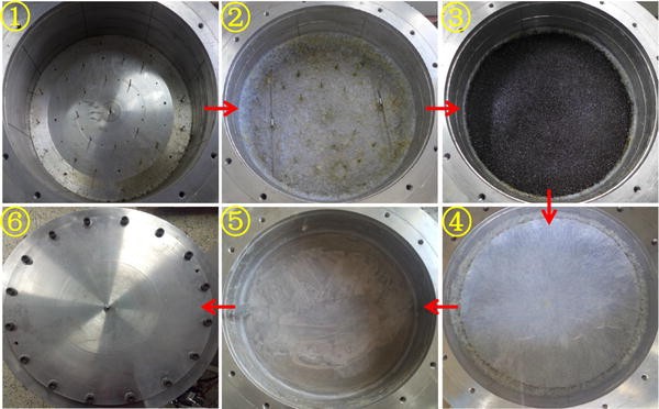
Position diagram of temperature probes, pressure probes, and horizontal wells in model
Fig. 3 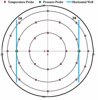
Process of filling the three-dimensional model
-
2.
Fill 5 cm thick clay over the bottom of model to simulate bottom cap rock, and paint the high-temperature glue on the surface of clay and the inner wall of model for channeling-control (Fig. 3②). High-temperature glue can resist highest temperatures of 350 °C, and could not react with oil, as well as impermeable after solidifying.
-
3.
Mix 9900 mL quartz sand with a mesh number of 6–10 and 300 mL water, add 3200 mL super heavy oil, and then mix uniformly to obtain the oil sand used in experiments. Fill the model with prepared oil sand, and press the oil sand (Fig. 3③). Oil sand has a cylinder shape with 5 cm thickness and 50 cm diameter, and horizontal wells are in the middle of oil sand.
-
4.
Put the high-temperature glue cushion over the oil sand for channeling-control (Fig. 3④).
-
5.
Fill the top of the model with clay to simulate top cap rock (Fig. 3⑤).
-
6.
Cover the model with the pressure-bearing cap to finish the filling process (Fig. 3⑥).


Experimental method and procedure
To facilitate the simulation and analysis, half of dual horizontal wells are chosen in the physical simulation experiments. By comparing the production performances of conventional steam stimulation with that of HDCS stimulation, development advantage and EOR mechanism of HDCS stimulation enhanced thermal recovery technology are studied. According to the chosen scaling criteria, corresponding parameters of reservoir prototype and model are calculated and shown in Table 3.
During the HDCS stimulation experiment, volume ratio of steam, carbon dioxide, and dissolver is 50:5:1. The injection parameters in each cycle of two stimulation schemes are determined and shown in Table 4. According to the injection parameters, stimulation experiments are conducted in two horizontal wells by turns, and the order of stimulation well is: 1#–2#–1#–2#–1#–2#.
Experiment procedures are shown as follows:
-
1.
Connect the experiment apparatuses according to the schematic, and test the system at 8 MPa for 2 h to make sure the system has good sealing.
-
2.
Finish the filling process according to the procedures above (Fig. 3), set the model temperature at 30 °C, and age the model under static status for 24 h.
-
3.
Set the temperature of steam generator to 250 °C and the quality of steam to 0.7. Open the steam injection valve of stimulation well when the steam meets the experiment requirement, inject 600 mL high-temperature steam, and then close the valve to soak for 0.4 min. Then open the liquid production valve of stimulation well to produce for 10.8 min. Cycle increment value of injected steam is 10 %. Two horizontal wells conduct the steam stimulation in turn for three cycles according to the procedures above. Record the oil and water production and corresponding time during the steam stimulation process.
-
4.
Dismantle and clean the model, repeat the procedures (1)–(2) to refill the model.
-
5.
Set the temperature of steam generator to 250 °C and the quality of steam to 0.7. Open the steam injection valve of stimulation well when the steam meets the experiment requirement. Inject 12 mL dissolver first, and then inject 60 mL carbon dioxide, and inject 600 mL high-temperature steam at last. Close the valve to soak for 0.4 min. Then open the liquid production valve of stimulation well to produce for 10.8 min. Cycle increment value of injected steam is 10 %, and the injection amounts of dissolver and carbon dioxide increase correspondingly. Two horizontal wells conduct the steam stimulation in turn for three cycles according to the procedures above. Record the oil and water production and corresponding time during the HDCS stimulation process.
Results and discussion
Temperature distribution
Extract the temperature data of temperature probes in model at the end of the first cycle of stimulation in 1# and the third cycle of stimulation in 2#. The temperature distributions of steam stimulation and HDCS stimulation are shown in Figs. 4 and 5, respectively. Through comparison, it can be seen that after the stimulations, the temperature around horizontal wells is high, and the heating range of HDCS stimulation is significantly larger than that of steam stimulation. This is because during the process of HDCS stimulation, early injected dissolver slug decreases the oil viscosity around horizontal wells, however, the amount of dissolver is not enough, which limits the range of viscosity reduction in oil layer. Then the injected carbon dioxide dissolves in crude oil, which further decreases the oil viscosity and drives the dissolver toward zones far away from wells, thus enlarges the effect range of dissolver in oil layer. When the subsequent steam is injected, oil viscosity of near-well zones quickly decreases due to the thermal effect of high temperature steam. As the reservoir temperature rises, solubility of carbon dioxide in crude oil quickly decreases, and separated carbon dioxide carries dissolver to surrounding areas with high oil viscosity, which further enlarges the effect range of carbon dioxide and dissolver. Meanwhile, due to its good mobility, carbon dioxide can carry the heat of steam to further range. HDCS stimulation realizes the rolling replacement of viscosity reduction effect of dissolver, carbon dioxide and steam, keeping the oil in steam front with low-viscosity, and enlarging the swept volume of steam and viscosity reduction range of super heavy oil by steam injection (Li et al. 2009).

Temperature distribution in model after the first cycle of stimulation in 1#. a Steam stimulation. b HDCS stimulation

Temperature distribution in model after the third cycle of stimulation in 2#. a Steam stimulation. b HDCS stimulation
Well bottom-hole pressure change
During the process of HDCS stimulation, injected oil-solute dissolver and carbon dioxide beforehand effectively decrease the oil viscosity of near-well zones, increase the mobility of crude oil, and decrease the subsequent steam injection pressure (Li et al. 2009), which is positive to the safety of construction site. Figure 6 shows the well bottom-hole pressure change of stimulation wells in the first cycle of steam stimulation and HDCS stimulation. It can be seen that the wellbore pressure of HDCS stimulation is about 0.7 MPa lower than that of steam stimulation when the steam injection ends. With the progress of production, release of carbon dioxide dissolved in crude oil continuously complements the consumption of reservoir energy, so pressure drops slower than that of steam stimulation. Dissolution and release of carbon dioxide in the super heavy oil play the role of increasing energy and cleanup.

Well bottom-hole pressure of stimulation wells in the first cycle of steam stimulation and HDCS stimulation
Oil properties change
Tables 5 and 6 show the SARA fractions and viscosity measurement results of produced oil in each cycle of steam stimulation and HDCS stimulation. Compared with the properties of initial oil sample, it can be seen that as the cycle of stimulation increases, the saturates and aromatics in produced oil increase gradually, the resins and asphaltenes in produced oil decrease gradually, and the change of oil fractions after HDCS stimulation is bigger than that after steam stimulation. Besides, the oil viscosities of produced oil from different cycles of stimulation are all lower than that of initial oil sample, and the decreasing degree of oil viscosity of produced oil from HDCS stimulation is larger than that from steam stimulation. This is because aquathermolysis reaction occurs between super heavy oil and high-temperature water under the high temperature steam conditions, which breaks down the macromolecular chains of heavy component, and generates saturates and aromatics (Clark et al. 1990; Hyne 1986; Wen et al. 2007). Besides, dissolver and carbon dioxide decrease the association degree of super heavy oil molecules, as well as the quantity and volume of micelle in super heavy oil (Zhang et al. 2000). Therefore, they synergistically decrease the oil viscosity and improve the rheological property of super heavy oil with the thermal effect of steam.
Oil recovery comparison
Figure 7 shows the oil recovery factor curves of steam stimulation and HDCS stimulation. It can be seen that oil recovery factor increases significantly in the first cycle, but the increase extent reduces gradually as the stimulation cycle increases. After three stimulation cycles, oil recovery factor of HDCS stimulation is 7.8 % higher than that of steam stimulation. It indicates that injecting dissolver and carbon dioxide increase thermal efficiency and swept volume of steam, all three synergistically play the role of chemistry, gas and heat for viscosity reduction, mixing and mass transfer, and increasing energy and cleanup.

Oil recovery factor curves of steam stimulation and HDCS stimulation
Conclusions
In this paper, development effect and mechanism of HDCS stimulation enhanced thermal recovery technology in super heavy oil reservoir are studied through three-dimensional physical simulation experiments. Compared with steam stimulation, main conclusions are shown as follows:
-
1.
HDCS stimulation realizes the rolling replacement of viscosity reduction effect of dissolver, carbon dioxide and steam, keeping the oil in steam front with low-viscosity, and enlarging the swept volume of steam and viscosity reduction range of super heavy oil by steam injection.
-
2.
Injecting oil-solute dissolver and carbon dioxide before the steam injection effectively decreases the viscosity of oil in near-well zones, and decreases the subsequent steam injection pressure, which is positive to the safety of construction site. Dissolution and release of carbon dioxide in the super heavy oil play the role of increasing energy and cleanup.
-
3.
Aquathermolysis reaction occurs between high temperature steam and super heavy oil, and dissolver and carbon dioxide break down the macromolecular chains and micelle of heavy component, which decreases the content of resins and asphaltenes, increases the content of saturates and aromatics, and has significant effect of upgrading and viscosity reduction for super heavy oil.
-
4.
Dissolver, carbon dioxide, and steam synergistically play the role of chemistry, gas and heat for viscosity reduction, mixing and mass transfer, and increasing energy and cleanup.
Abbreviations
- α :
-
Thermal diffusivity (m2/s)
- Δρ :
-
Density difference between oil and water (kg/m3)
- L v :
-
Latent heat vaporization of saturated steam (kJ/kg)
- x :
-
Steam quality, cumulative oil, dimensionless
- ΔT :
-
Temperature difference between steam and reservoir (°C)
- v :
-
Steam injection rate (m3/day)
- t :
-
Time (day)
- K :
-
Permeability (μm2)
- g :
-
Gravitational acceleration (m/s2)
- μ o :
-
Oil viscosity (mPa s)
- C w :
-
Specific heat capacity of saturated hot water [J/(kg °C)]
- q :
-
Cyclic steam injection volume (m3)
References
Butler RM (1991) Thermal recovery of oil and bitumen. Prentice Hall, New Jersey
Butler RM, Mokrys IJ (1991) A new process (VAPEX) for recovering heavy oils using hot water and hydrocarbon vapour. J Can Pet Technol 30(1):97–106
Butler RM, Mokrys IJ (1993) Recovery of heavy oils using vapourized hydrocarbon solvents: further development of the VAPEX process. J Can Pet Technol 32(6):56–62
Clark PD, Clarke RA, Hyne JB et al (1990) Studies on the chemical reactions of heavy oils under steam stimulation condition. AOSTRA J Res 29(6):292–391
Gu WH, Liu YT (2012) Orthogonal parameters optimization design for injection and production herringbone well in steam stimulated heavy oil reservoir. Well Test 21(4):4–6
Hyne (1986) Aquathermolysis-A synopsis work on the chemical reaction between water (steam) and heavy oil sands during simulated stimulation. Synop Rep No 50:845–849
Khataniar S, Kamath V A, Patil S L (1999) CO2 and miscible gas injection for enhanced recovery of Schrader Bluff heavy oil. In: Paper SPE 54085 presented at the 1999 SPE international thermal operations and heavy oil symposium held in Bakersfield
Li BF, Zhang JG, Tao L et al (2009) Mechanism research on HDCS high efficiency exploitation technology for ultra-heavy oil reservoir. Drill Prod Technol 32(6):52–55
Li H, Sun JF, Shi JP (2010) Research and application on CO2 and dissolver assisted horizontal well steam-injection to develop super heavy oil. In: Paper SPE 131061 presented at the CPS/SPE international oil and gas conference and exhibition in China held in Beijing
Li ZM, Lu T, Tao L et al (2011) CO2 and viscosity breaker assisted steam huff and puff technology for horizontal wells in a super-heavy oil reservoir. Pet Explor Dev 38(5):600–605
Li HH, Bi WW, Xu XL et al (2013) Study on production technology of HDCS for super and extra heavy oil production in mid-deep formation. Spec Oil Gas Reserv 20(2):87–89
Liu WZ (1998) An overview on thermal development mode of super viscous crude oil and extra viscous crude oil reservoir. Spec Oil Gas Reserv 5(3):1–7
Liu HQ, Chen YM, Zhou B et al (1995) Optimization design of steam soak in Wa 38 Oilfield. J Univ Pet China 19(1):47–50
Liu W, Li ZM, Sun XN et al (2013) The effect of the elements in HDCS technology on the properties of super heavy oil. Spec Oil Gas Reserv 20(4):127–130
Luigi B, Alberto D, Amelia L et al (1994) An innovative way to produce and transport heavy oil through dispersion in water: laboratory study and field test results. In: Paper SPE 28543 presented at the SPE 69th annual technical conference and exhibition held in New Orleans
Miller JS, Jones RA (1981) A laboratory study to determine physical characteristic of heavy oil after CO2 saturation. In: Paper SPE/DOE 9789 presented at the 1981 SPE/DOE second joint symposium on enhanced oil recovery of the society of petroleum engineers held in Tulsa
Nasr TN, Ayodele OR (2005) Thermal techniques for the recovery of heavy oil and bitumen. In: Paper SPE 97488 presented at the SPE international improved oil recovery conference in Asia Pacific held in Kuala Lumpur
Nie JH, Tang ZH (2013) The discovery and application of HDCS technology in Mao-8 Block. Petrochem Ind Appl 32(6):28–30
Olenick S, Schroeder FA, Haines HK et al (1992) Cyclic CO2 injection for heavy-oil recovery in Halfmoon Field: laboratory evaluation and pilot performance. In: Paper SPE 24645 presented at the 67th annual technical conference and exhibition of the society of petroleum engineers held in Washington, DC
Petit H, Renard G, Valentin E (1989) Technical and economic evaluation of steam injection with horizontal wells for two typical heavy-oil reservoirs. In: Paper SPE 19828 presented at the 64th annual technical conference and exhibition of the society of petroleum engineers held in San Antonio
Pradeep AG, Swapan D, Sanjay S et al (2008) Expanding solvent SAGD in heavy oil reservoirs. In: Paper SPE/PS/CHOA 117571 presented at the 2008 SPE international thermal operations and heavy oil symposium held in Calgary
Pujol L, Boberg TC (1972) Scaling accuracy of laboratory steamflooding models. In: Paper SPE 4191 presented at the California regional meeting of the society of petroleum engineers of AIME held in Bakersfield
Rojas GA, Ali SMF (1988) Dynamics of subcritical CO2/brine floods for heavy oil recovery. In: SPE 13598
Sarkar AK, Sarathi PS, Strycker AR (1994) Use of horizontal wells for improving steamflood performance of a thin low-permeability heavy-oil reservoir. In: Paper SPE/DOE 27806 presented at the SPE/DOE ninth symposium on improved oil recovery held in Tulsa
Shan XL, Che CB, Li J et al (2007) Present status of oil sand resources at home and abroad. Glob Geol 26(4):459–464
Simon R (1965) Generalized correlations for predicting solubility, swelling and viscosity behavior of CO2-crude oil systems. JPT 17(1):102–107
Sun JF, Li ZQ, Wu GH (2011) Advancement and application of thermal recovery technology in heavy oil reservoir in Shengli Petroleum Province. In: Paper SPE 14582 presented at the international petroleum technology conference held in Bangkok, Thailand
Sun JF, Yang Y, Wu GH et al (2012) Research and application on nitrogen and dissolver assisted horizontal well steam-injection to develop shallow thin super heavy oil reservoirs. In: Paper SPE 154010 presented at the eighteenth SPE improved oil recovery symposium held in Tulsa
Tao L, Li Z M, Zhang N et al (2009) CO2 capture and for improving heavy oil recovery. In: IEEE, APPEEC MAR 28–31
Wang KJ (2013) Technical limits of HDCS for developing deep extra-heavy oil reservoirs. Spec Oil Gas Reserv 20(6):93–95
Wang CZ, Li ZM, Liu W et al (2014) Physical simulation of steam drive after HDCS. Spec Oil Gas Reserv 21(4):93–96
Wen SB, Zhao YJ, Liu YJ et al (2007) A study on catalytic aquathermolysis of heavy crude oil during steam stimulation. In: Paper SPE 106180 presented at the 2007 SPE international symposium on oilfield chemistry held in Houston
Yang YX (2012) Research and application on HDCS development technology for super-deep heavy oil. Fault-Block Oil Gas Field 19(1):64–67
Zerpa LB (1995) Numerical simulation of horizontal wells in a heavy crude reservoir in Venezuela. In: Paper SPE 30282 presented at the international heavy oil symposium held In Calgary
Zhang XB (2006) Applied research of steam-carbon dioxide-auxiliary agent huff and puff technology. Acta Pet Sin 27(2):80–84
Zhang Y, Zhao MM, Zhou FS et al (2000) Maleic anhydride-styrene-C18 alkylacrylate terpolymer as viscosity reducer for viscous crude oil: preparation and use. Oilfield Chem 17(4):295–298
Zhu GL (2011) Water coning mechanism and HDCS laboratory research for deep heavy oil reservoirs. Spec Oil Gas Reserv 18(4):90–93
Acknowledgments
This study is funded by National Science and Technology Major Projects of China (2011ZX05009-004-05) and Major Projects of CNOOC Ltd. (YXKY-2013-TJ-02).
Author information
Authors and Affiliations
Corresponding author
Rights and permissions
Open Access This article is distributed under the terms of the Creative Commons Attribution 4.0 International License (http://creativecommons.org/licenses/by/4.0/), which permits unrestricted use, distribution, and reproduction in any medium, provided you give appropriate credit to the original author(s) and the source, provide a link to the Creative Commons license, and indicate if changes were made.
About this article

Cite this article
Wang, C., Liu, H., Wang, J. et al. Three-dimensional physical simulation experiment study on carbon dioxide and dissolver assisted horizontal well steam stimulation in super heavy oil reservoirs. J Petrol Explor Prod Technol 6, 825–834 (2016). https://doi.org/10.1007/s13202-016-0234-x
Received:
Accepted:
Published:
Issue Date:
DOI: https://doi.org/10.1007/s13202-016-0234-x