Abstract
Absolute calibration of small-angle scattering (SAS) intensity data (measured in terms of the differential scattering cross section per unit sample volume per unit solid angle) is essential for many important aspects of quantitative SAS analysis, such as obtaining the number density, volume fraction, and specific surface area of the scatterers. It also enables scattering data from different instruments (light, X-ray, or neutron scattering) to be combined, and it can even be useful to detect the existence of artifacts in the experimental data. Different primary or secondary calibration methods are available. In the latter case, absolute intensity calibration requires a stable artifact with the necessary scattering profile. Glassy carbon has sometimes been selected as this intensity calibration standard. Here we review the spatial homogeneity and temporal stability of one type of commercially available glassy carbon that is being used as an intensity calibration standard at a number of SAS facilities. We demonstrate that glassy carbon is sufficiently homogeneous and stable during routine use to be relied upon as a suitable standard for absolute intensity calibration of SAS data.
1 Introduction
Small-angle scattering (SAS) is a nondestructive technique in which the elastic scattering of radiation from density inhomogeneities within a sample is recorded at low scattering angles.[1] The SAS techniques include small-angle X-ray scattering (SAXS), small-angle neutron scattering (SANS), and low-angle light scattering, among others. The SAS data contain information about the size, shape, volume, and total surface area of the scatterers, as well as the characteristic distances between ordered or partially ordered scatterers. The technique of SAS has been widely used to advantage in fields such as metallurgy, ceramics, polymer science, colloids, nanocrystalline materials science, and, increasingly, biology.
In SAS experiments, the measured scattering intensity I(q) is related to the differential scattering cross section per unit sample volume per unit solid angle, which is a measure of the absolute scattering probability of the sample material. The absolute scattering probability is derived from the morphology and from the difference in scattering length density between scattering inhomogeneities and the surrounding medium. The scattering length is the intrinsic scattering strength (scattering amplitude or atomic form factor) of each atom for X-rays, neutrons, or light and is given in published tables. Thus, it is inherent to the composition and structure of the specific sample.[2] Here, \( |{\mathbf{q}}| = \left( {{{4\pi } \mathord{\left/ {\vphantom {{4\pi } \lambda }} \right. \kern-\nulldelimiterspace} \lambda }} \right)\sin \theta \) is the magnitude of the scattering vector, q, where λ is the wavelength of the incident radiation (X-rays or neutrons) and 2θ is the scattering angle. The absolute intensity, expressed as a function of q, is the “macroscopic SAS differential scattering cross section,” defined as the probability per unit time (s−1), per unit sample volume (cm−3), per unit incident flux (1/(cm−2 s−1)), of scattering into a unit solid angle (sr−1) centered on a particular scattering direction associated with the direction and magnitude of q. Hence, the units are cm−1 sr−1. For a circularly symmetric scattering system, the azimuthal angle can be ignored, and q can be replaced by q.
When SAS data are uncalibrated, the measured intensity is reported in arbitrary units and is a function of sample thickness, scattering geometry, and measurement time. Meaningful analyses such as Guinier fits or derivations of the correlation function[1] can be performed on uncalibrated data. However, analysis of far greater quantitative value becomes possible when the scattering intensity is absolutely calibrated. Absolute calibration is required to correlate the measured intensity with the differential SAS cross section of the sample material. The absolutely calibrated scattering intensity is expressed as the ratio of the measured scattering intensity to the incident beam intensity. Such absolutely calibrated intensities can then be used, for example, to determine the number density (or volume fraction) and the specific surface area of the scatterers from the scattering length densities of one or more phases in a multiphase system. Furthermore, absolute intensities can be used to restrict the fitting parameters of a given model to match the observed intensities.[3]
Absolute intensity calibration enables scattering data from the same sample to be directly compared and intercalibrated among different instruments for which the q ranges, wavelengths, and scattering geometries are routinely different.[4,5] For example, a typical scattering q range of a synchrotron SAXS beamline or a SANS instrument is 0.005 to 1 Å−1, while ultra-small-angle X-ray scattering (USAXS) instruments have a scattering q range of 0.0001 to 0.5 Å−1. Absolute intensity calibration allows these measurements to be combined to cover 4 decades in q. Furthermore, as Wignall and Bates[3] pointed out, absolute intensity calibration can be a sensitive tool to detect the existence of artifacts in the experimental data.
The importance of the absolute calibration of SAS intensity has been recognized since the very early stages of its technical development, for both X-rays[6–8] and neutrons.[3,9] Despite the acknowledged advantage of placing data on the absolute scale, the use of suitable calibration techniques is by no means straightforward in the field of SAS. The two generally used methods for absolute calibration of scattering data are “primary,”[3,5,10,11] in which the scattering probability is measured by direct comparison with the incident beam intensity (attenuated by a known amount if necessary for protection of the detector), or “secondary,” in which the scattering intensity from the sample is compared with that from a calibration standard sample of known scattering cross section. Intensity calibration standard samples can themselves be divided into primary and secondary standards depending on whether they have been calibrated using the preceding primary method or by simply comparing their scattering intensity against that of some other primary calibration sample.
The primary calibration method frequently requires mechanical attenuation of the incident beam, which is easy to implement in principle but, in practice, requires precise fabrication of a chemically pure attenuator, a thorough understanding of the scattering process, and knowledge or assessment of potential wavelength dependencies of the attenuation. Additionally, detailed analysis of the attenuator transmission measurements is frequently nontrivial.[12,13] The secondary calibration method has been successful at high-flux sources,[14] and often uses primary intensity calibration standards, such as water and pure liquids, whose differential scattering cross sections are related to their isothermal compressibilities. While these are usually appropriate standards for biosciences, their X-ray scattering cross sections are too low to be adopted as a general SAXS standard, especially in the areas of materials science, polymer science, ceramics, chemistry, etc. Monodisperse colloidal suspensions have also been used as primary intensity calibration standards,[8] for which the differential cross section is obtained from their well-defined internal surface area according to Porod’s law. Unfortunately, the metastable nature of these colloidal systems leaves their long-term use in question.
A USAXS instrument, designed after the Bonse–Hart double-crystal configuration,[15–17] offers a primary method of providing an absolute intensity calibration without the need for beam attenuation or an intensity calibration standard sample of any kind.[15] The instrument at the Advanced Photon Source (APS), Argonne National Laboratory,[16] takes advantage of a silicon photodiode detector that gives a linear signal response over 11 decades of scattering intensity,[18] enabling it to measure the full incident beam intensity without loss of linearity. As a result, absolute calibration is obtained as an inherent property of the USAXS data without requiring separate calibration measurements. With a standard USAXS configuration, USAXS data are intrinsically slit smeared. However, for the randomly oriented microstructure found in glassy carbon, the data are readily desmeared using the well-established Lake algorithm[19] to provide intensity data appropriate to pinhole collimation. This allows desmeared USAXS data to be readily compared with pinhole SAXS (or SANS) data measured elsewhere. Thus, the USAXS instrument can be used to provide primary intensity calibration standard samples for calibrating the scattering intensity at other SAXS instruments (using the secondary method described above).
As mentioned previously, various standard materials for intensity calibration are used in SAS studies. For a general SAS standard, the material should be a scatterer with appropriate scattering strength for a given problem and, ideally, should be applicable to both SAXS and SANS. Among the many intensity calibration standard materials, glassy carbon has long been identified and used informally as a calibration standard.[3,20] Glassy carbons, also known as polymer carbons, are compact nongraphitic, nonfullerene carbons that are produced by the controlled pyrolysis of a thermosetting resin.[20] Its structure has been studied in detail. The scattering arises from voids in the carbon matrix, and Rothwell[21] first studied the microporosity of glassy carbons using SAXS. Wignall and Ping[22] modeled the SAXS profile of glassy carbon by the Debye–Bueche two-phase model.[23] Previous work has also demonstrated that the glassy carbon structure has a good temperature tolerance.[20]
In this article, we investigate in detail the structural uniformity of a set of glassy carbon samples. We take advantage of the primary calibration capability of USAXS and compare results obtained for the same samples at both neutron and X-ray sources. Furthermore, we study the long-term stability of glassy carbon by measuring the same sample over a span of 5 years. We discuss the accuracy, suitability, and ease of use of glassy carbon as a general absolute intensity calibration standard material.
2 Experimental Methods
2.1 Materials
Commercially available glassy carbon plates were procured from Alpha AesarFootnote 1 (Ward Hill, MA, stock number 38021). The glassy carbon plates have dimensions of 50 mm × 50 mm × 1 mm. The density at 20 °C for individual samples lies in the range 1.4 to 1.5 g/cm3. A second glassy carbon produced with a different processing routine was also procured from the same manufacturer (stock number 38024). Initial tests were performed on both types of glassy carbon plates, and the first type was found to exhibit stronger scattering in the q range: 0.01 < q < 1 Å−1. Since the more strongly scattering sample better matched the flux and q-range requirements for the scientific problems where we envision this standard to be used, we will confine our discussion to this first type of glassy carbon.
The thickness of each glassy carbon plate was measured by micrometer and was found to be (1.00 ± 0.01) mm, where the ± value was the standard deviation on a single measurement and this convention is used here throughout. We selected samples from five plates, denoted 1 through 5, respectively. Among them, sample 1 was identified by fabrication lot C12N43 and samples 2 through 5 were identified by fabrication lot E16N45.
We also used a noncommercial glassy carbon sample (subjected to a final heat treatment at 2800 °C for 24 hours and denoted HT) to compare the absolute intensity calibrations between the USAXS instrument at the APS and the 8-m SANS instrument at the NIST Center for Neutron Research (NCNR). This HT glassy carbon exhibits scattering over a wider q range and with greater intensity in the low q region than does the commercial glassy carbon. The detailed fabrication recipe of the HT glassy carbon is given elsewhere.[24] The HT glassy carbon sample used had a thickness of (0.39 ± 0.01) mm. Absolute intensity calibration at the NIST 8-m SANS instrument was determined by comparing the glassy carbon scattering intensity with that for a silica secondary intensity calibration standard.
2.2 USAXS Measurements
The USAXS measurements were conducted using an instrument built in partnership with the National Institute of Standards and Technology (NIST). It was located originally at beam line 33-ID and moved later to 32-ID at the APS. This USAXS instrument employs Bonse–Hart type double-crystal optics to extend the SAXS q range to a very small q value (≈10−4 Å−1). Ilavsky et al.[16] have given a detailed description of this instrument. It provides a primary method of absolute intensity calibration[15] for samples of known thickness.
We measured the USAXS intensity over a q range from 0.0001 to 0.5 Å−1 with a q resolution of 1 × 10⁻⁴ Å−1. The beam size was 2 mm × 1 mm. Monochromatic X-ray energies, from a Si (111) monochromator, varied between experiments over the range of 10 to 12 keV, with an incident photon flux on the sample ≈1 × 10¹³ s−1. Each scan took approximately 15 minutes. The data were reduced and analyzed using the Indra and Irena tool suites for SAS reduction and analysis.[25,26] The USAXS data reduction software provides estimates of the experimental uncertainty standard deviations of the measured intensity data (also known as errors), which are used throughout this article.
2.3 SAXS Measurements
The SAXS measurements were conducted at DND-CAT, Sector 5 at the APS using an X-ray energy of 15 keV and a sample-to-detector distance of 2490 mm. Data were collected using the low-background pinhole facility.[27] Samples were mounted in the same vacuum (<0.13 kPa or 10−3 Torr) as found throughout the flight path. To characterize the microstructural variability by SAXS, samples were measured in a raster pattern of 16 × 16 measurements with a 2-mm spacing between the measurement positions, resulting in 256 separate measurements. A beam size of 100 μm × 100 μm was used with 2-second exposure time. Also, multiple measurements (35 times) were made at a single sample position on one of the samples to determine the reproducibility of the detector response. All of the data were reduced using standard reduction methods[27] and the scattering intensity calibrated (a secondary method) by comparison with the absolute-calibrated USAXS measurements. Since the data reduction software used at this SAXS instrument does not provide estimated (or other) uncertainties of the data, we have used a statistical analysis described later in the article. We have used a statistical analysis of the 35 repeated measurements taken at one place on a sample to measure the SAXS camera intensity reproducibility and a statistical analysis of 256 different places on each sample to measure the microstructure variability.
2.4 SANS Measurement
The SANS measurements were conducted on the 8-m SANS instrument at NCNR.[28] This instrument had a q range of 0.005 to 0.5 Å−1. The beam diameter for these measurements was 5 mm. Measurements were made using neutron wavelengths of 6 and 8 Å. The NIST SANS data reduction software provides estimated uncertainties for measured data intensities, and these are used throughout this article. The SANS scattering cross section was calibrated by means of a silica secondary intensity calibration standard, “Si 2A.”
3 Results
3.1 Confirmation of USAXS-SANS Calibration
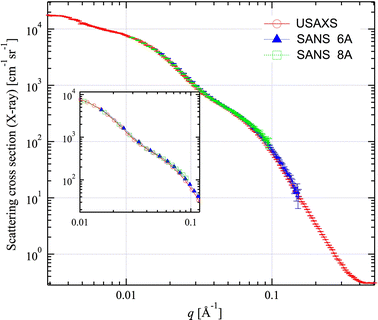
In Section II, we introduced USAXS measurements as a primary absolute intensity calibration technique. To compare the performance of the USAXS instrument at APS with the SANS instrument at NIST, we performed USAXS and SANS experiments on the same HT glassy carbon sample. The SANS scattering cross section was calibrated by means of a silica secondary intensity calibration standard.
As well as the difference in using neutrons and X-rays, the wavelengths used were also rather different: 6 and 8 Å for SANS and 1.04 Å for USAXS. The scattering length densities for glassy carbon with X-rays and with neutrons can be determined from published tables of the X-ray and neutron scattering lengths.[29,30] The calculated ratio between scattering length densities of X-rays and neutrons for carbon is 2.527. The corresponding ratio of the X-ray and neutron scattering contrast factors arising from scattering between the solid carbon and the microvoids is the ratio of the squares of the scattering length densities and, consequently, is 6.385. Thus, the absolute calibrated SANS data were scaled to the USAXS data by multiplying them by 6.385, and the results are shown in Figure 1.
Comparison of X-ray (desmeared USAXS) and neutron SAS data for the HT glassy carbon sample. Neutron data were scaled to the X-ray contrast by multiplying by 6.385. Vertical bars on the data represent estimated uncertainities provided by SANS and USAXS data reduction software packages. The vertical bars with uncertainities are removed from the inset for readability
We find agreement between the scaled absolute calibrated SANS data and the primary calibrated USAXS data to within the estimated experimental uncertainties of the measurement provided by the data reduction software. The very small deviation between the datasets in the high-q region is related to the imperfect flat background subtraction for the SANS data. This comparison experimentally confirms the agreement between the two calibration methods and provides a confidence level for the HT glassy carbon material as a general intensity calibration standard over a q range from 0.008 to 0.3 Å−1.
3.2 Suitability of Glassy Carbon as an Intensity Calibration Standard
For a material to serve the need for a robust intensity calibration standard, several conditions need to be met. The requirements are as follows.
-
(1)
The spatial variability of the microstructure must be minimal.
-
(2)
Resistance to radiation damage must be sufficient to provide acceptable stability in the scattering intensity vs q during regular use over extended periods.
-
(3)
The shelf life and sample robustness must be sufficient to provide acceptable stability over an extended period during regular use.
The results will be discussed in detail with respect to these conditions in Sections 1 through 3.
3.2.1 Microstructural spatial variability
Minimal spatial variability of the microstructure is important for the use of intensity calibration standards on instruments of different geometries, where it is not possible to guarantee that the same area on the sample is used for the calibration measurements. For example, a typical beam size for synchrotron pinhole SAXS experiments is ≈100 μm × 100 μm; for USAXS, it is ≈2 mm × 1 mm (but can be as small as for pinhole SAXS); and for SANS, it is ≈1 cm × 1 cm. Therefore, it is imperative that the microstructure of the standard be spatially homogeneous to within the same uncertainty as required for the calibration.
To establish the degree of spatial variability of glassy carbon, we measured each sample plate multiple (256) times across the entire plate area, with the pinhole SAXS instrument using a 100 μm × 100 μm beam cross section, and evaluated the statistical variation. The experimental details are described in Section II–C. The data were reduced and calibrated to absolute intensity by scaling the average pinhole SAXS intensity to the USAXS intensity at the same q measured on each sample using a beam cross section of 2 mm × 1 mm. To characterize the variability, we performed statistical analysis on these fully reduced and calibrated data. For each measured scattering vector q, we calculated the following parameters.
-
(1)
The average intensity is given by
$$ Y_{\text{avg}} = {\frac{{\sum\limits_{i = 1}^{N} {Y_{i} } }}{N}} $$(1)where Y i are the measured intensities and Y avg is the average intensity of the N (256) measurements made.
-
(2)
The standard deviation of the average intensity, σ, given by
$$ \sigma = \sqrt {{\frac{{\sum\limits_{i = 1}^{N} {(Y_{i} - Y_{\text{avg}} )^{2} } }}{N - 1}}} $$(2) -
(3)
The minimum and maximum values for the intensity at each q were found among the 256 measurements, from which was deduced the minimum and maximum deviation from the average (DA).
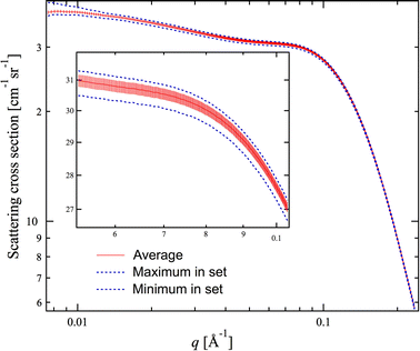
Figure 2 presents SAS data for one of the glassy carbon samples (denoted “001”) showing the average scattering cross section vs q, its standard deviation, as well as the minimum and maximum scattering cross sections in the data set. The inset shows detail near 0.1 Å−1. We see that the 256 sets of data collected at different positions on the sample are all close to the average intensity: the average standard deviation for q > 0.01 Å−1, expressed as a fraction of the measured intensity at each point, is less than 0.8 pct. Similarly, the maximum deviation, expressed as a fraction of the measured intensity at each point, is less than 2 pct for the data at q > 0.01 Å−1. The spatial homogeneity of the sample microstructure therefore is established to within 2 pct.
Statistical analysis of pinhole SAXS data for sample 001. The inset shows detail near 0.1 Å−1. The scaled average scattering cross section is shown by the solid line, with the standard deviation of scattering cross sections at specified q illustrated by the vertical bars. The dotted lines show the maximum and minimum values at given q values for the 256 data sets
Figure 3 shows the variability of the average scattering cross sections among the samples, as determined from the 256 pinhole SAXS measurements made on each different sample. Recall that the sample denoted “001” belongs to a different manufacturing lot than the other four samples (denoted “002” through “005”). The graph shows that while there are significant microstructural differences between samples from different lots (>10 pct), within a single lot, the sample microstructures are much more similar (to within ≈5 pct, spread of ≈±2.5 pct about the mean value).
Average scattering cross section (based on multiple pinhole SAXS measurements) for samples 001 to 005 as a function of q. Note that the variations between the lots is >10 pct, while the variation within one lot (002 to 005) is ≈±2.5 pct about a mean value. Vertical bars illustrate the computed standard deviation uncertainties on individual data points. They are shown for only one dataset to preserve clarity
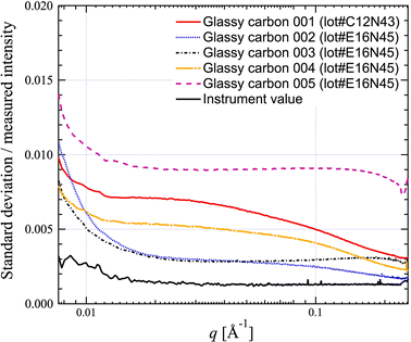
To facilitate an understanding of the variability of the microstructure on different length scales (at different q values), the standard deviations, and the minimum and maximum deviations, were converted into fractional values by dividing each value by the average intensity for the specified q. Furthermore, we performed statistical analysis with a set of 35 meaurements on the same sample position in order to provide a measure of the variability of the pinhole SAXS camera, itself. Figure 4 shows the variation of the fractional standard deviations for all five samples and the SAXS camera. The SAXS camera fractional standard deviation is generally ≈0.002 and, over the entire measured q range, is always <0.003, smaller than the fractional standard deviations measured on the samples. The camera fractional standard deviation shows a slight q dependence, because the noise is related to the measured intensity, which is a function of q. Significant differences occur among the five samples, where sample “005” exhibits significantly larger variability than the other samples, even from the same lot. For the majority of the q range that is relevant to typical SAXS instruments, the relative standard deviation is <0.01 (1 pct), whereas at q values smaller than 0.01 Å−1, the relative standard deviation can be as large as 0.015 (1.5 pct).
Relative variability of the microstructure (measured standard deviation at each q value divided by the average intensity of the different measurements at that q value) as a function of q. The fractional standard deviation of the pinhole SAXS camera (obtained by statistical analysis of 35 measurements at the same place on one sample) is also given as a function of q
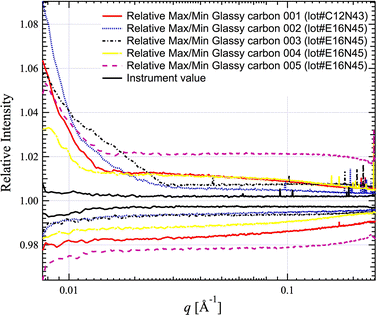
Figure 5 shows the relative minimum and maximum DA values, which can be assumed to be a good approximation of the extremes in microstructure and measurement variations, for all five measured samples (256 pinhole SAXS datasets each) and the SAXS camera (35 datasets). The relative DAs of the SAXS camera are approximately ±0.004 (0.4 pct) for all measured q values. The relative minimum and maximum DA for glassy carbon samples vary with q. For higher q (above 0.02 Å−1), the relative DAs are less than ±0.025 (2.5 pct) from the average. For lower q values, these relative DAs increase and can reach up to 10 pct at the lowest q values measured. These results suggest that in order to use glassy carbon as an absolute intensity calibration standard, the part of the scattering profile with q greater than 0.01 Å−1 should be used.
3.2.2 Stability during regular use
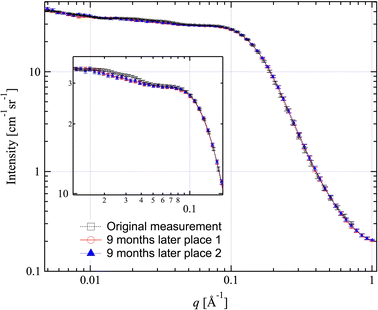
A microstructure stability evaluation was made for one glassy carbon sample during routine use as an intensity calibration standard at the DND-CAT pinhole SAXS instrument. The measurements were made over a period of 9 months. The sample was routinely exposed to radiation under low vacuum when used inside the SAXS camera chamber. It was stored on the APS experimental floor, where atmospheric conditions vary significantly at different times of the year. During the summer, the relative humidity is high (up to 80 pct), while during winter, it can be as low as 20 pct. The temperature varies between 20 °C and 25 °C. No special precautions were taken to protect the sample, other than to store it in a plastic container. Figure 6 shows the scattering profile of the sample before and after 9 months of use, as measured by the USAXS instrument. The sample dimension was 15 mm × 15 mm, while the USAXS beam size was 2 mm × 1 mm. Consequently, the measurements may not have been taken at the exact same sample position for each measurement. For this reason, at least two scattering profiles from two different sample positions were collected after the 9-month use on the SAXS instrument. The USAXS data were collected using a wavelength of 1.03 Å. Figure 6 shows that all three scattering profiles agree with each other within the estimated uncertainties throughout the measured q range. The reproducibility of the USAXS measurements indicates that the microstructure of the glassy carbon meets the requirements for stability and is not subject to change due to atmosphere, in-and-out-of vacuum procedures, and considerable exposure to X-ray radiation.
Comparison of scattering cross sections for a glassy carbon intensity calibration standard used at a pinhole SAXS camera (DND-CAT) before and after 9 months of regular use. The data shown here were collected with the USAXS instrument and desmeared. Vertical bars indicate the estimated uncertainties (some removed for clarity)
The vulnerability to radiation damage of the glassy carbon samples was tested in multiple measurements at the same position on the sample. For short exposures, we used data from the pinhole SAXS DND-CAT measurements, where the same position on the sample was exposed for 35 measurements (each with 2-second exposure). For exposures to higher doses, we used USAXS measurements, where the same position on the sample was measured 20 times. Each measurement exposed the sample for about 15 minutes to the incident photon flux of ≈1013 s−1 over an area of ≈2 mm2. These 20 measurements represent a total exposure of ≈5 hours, or a dose of ≈2 × 10¹⁷ photons over the 2 mm2 beam area. No significant changes to the microstructure were found during any of these measurements.
3.2.3 Stability over an extended period of time
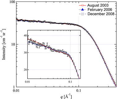
A stability test was also performed on one Alpha Aesar glassy carbon sample over a span of 5 years. The sample was stored in a plastic container under room conditions on the APS experimental floor. The USAXS measurements on the sample were made in August 2003, February 2006, and December 2008, and the results are shown in Figure 7. As in the preceding case, the exact same position cannot be guaranteed for these measurements, as the sample was approximately 15 mm × 15 mm in size, while the USAXS beam size was 2 mm × 1 mm. Figure 7 demonstrates that the scattering profile of the sample remains essentially the same within the estimated uncertainties over this extended time span. This result demonstrates that the microstructure of glassy carbon does not change over extended timescales and glassy carbon is stable as an absolute intensity calibration standard.
3.3 Procedure for using Glassy Carbon as an Intensity Calibration Standard
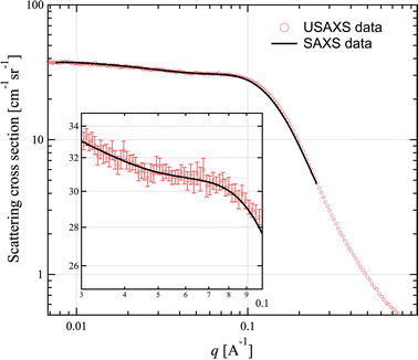
Figure 8 shows the differential scattering cross section vs q for one glassy carbon sample, as measured by both the USAXS and SAXS instruments. After correction for the detector response (SAXS) and subtraction of both the empty beam and flat background scattering (separately for USAXS and SAXS), and desmearing of the USAXS data, the scattering profiles agree within the uncertainties. The USAXS data are absolutely calibrated using the primary method. To establish an absolute calibration for a pinhole SAXS camera, the SAXS data need to be scaled to the desmeared USAXS data in the pinhole SAXS q range. The scaling factor can be obtained from a linear fit between the USAXS and SAXS data in this q range. Once the scaling factor is determined, it can be used to scale other SAXS data collected by means of the same pinhole SAXS configuration to obtain the absolutely calibrated scattering cross section as a function of q.
Comparison of desmeared USAXS data and pinhole SAXS data. In the inset, the USAXS data are shown with the vertical bars indicating the estimated uncertainties for each point. SAXS data (vertical bars for the uncertainties here removed for clarity) are scaled to the USAXS data between 0.01 and 0.1 Å−1
3.4 Current Preparation of Ad Hoc Intensity Calibration Standard Samples
Presently at APS, glassy carbon samples are cut to size using a water-cooled diamond saw. The mounting material is cleaned off the glassy carbon samples, which are then dried in a furnace (at ≈150 °C) to remove residue solvent. Each sample is measured several times at several different sample positions using the USAXS instrument to verify the sample homogeneity. Once the spatial homogeneity is established (to within the uncertainties discussed previously) the samples can serve as intensity calibration standards and are provided upon request to one of the authors (JI), along with the corresponding desmeared USAXS data. Using the results of the material variability analysis documented previously and estimates for USAXS measurement variability, we anticipate that intensity calibrations performed using such a standard should be consistent to less than ±5 pct.
Currently, there are 21 such glassy carbon intensity calibration standard samples in use around the world that have been calibrated at the APS. They are found at large facilities, such as synchrotron SAXS instruments, as well as at SANS instruments at reactor and spallation neutron sources. Moreover, at least half of the calibration samples are in use at desktop SAXS instruments in industrial and academic laboratory settings.
4 Conclusions
Absolute intensity calibration is an integral part of SAS data analysis. It relates the measured intensity directly to the physically meaningful differential scattering cross section of the sample. In this article, we have described in detail an absolute calibration method based on a primary calibration instrument (the USAXS instrument at APS sector 32-ID) making use of a well-known, commercially available sample (glassy carbon). Further, we have experimentally established that there is agreement (to within the experimental uncertainties) between self-calibrated desmeared USAXS results and absolutely calibrated SANS results for a glassy carbon sample to provide justification for the accurary of USAXS as a primary calibration tool. The spatial homogeneitity of the glassy carbon has been established by collecting multiple (256) sets of pinhole SAXS data at different positions on the sample, and the standard deviations have been found to be less than 0.8 pct in the q range of importance. The glassy carbon microstructure has also been shown to be stable over time and is not affected by atmosphere or radiation exposure. The appropriate q range and a routine procedure to use glassy carbon as an intensity calibration standard have been developed. As an ad hoc standard, calibrated glassy carbon samples are being made available to research laboratories and facilities around the world in order to facilitate in-depth SAS analysis.
Notes
Certain commercial equipment, instruments, software, or materials are identified in this article to foster understanding. Such identification does not imply recommendation or endorsement by the Department of Commerce or the National Institute of Standards and Technology, nor does it imply that the materials or equipment identified are necessarily the best available for the purpose.
References
O. Glatter and O. Kratky: Small-Angle X-ray Scattering, Academic Press, London, 1982, pp. 17–51.
J. Als-Nielsen and D. McMorrow: Elements of Modern X-ray Physics, John Wiley and Sons, New York, NY, 2001, pp. 1–26.
G.D. Wignall and F.S. Bates: J. Appl. Cryst., 1987, vol. 20, pp. 28–40.
S.M. King: Modern Techniques for Polymer Characterization, John Wiley, New York, NY, 1999, ch. 7, pp. 171–232.
P. Lindner: Neutron, X-rays and Light. Scattering Methods Applied to Soft Condensed Matter, North-Holland, New York, NY, 2002, pp. 23–48.
O. Kratky: Z. Anal. Chem., 1964, vol. 201, pp. 161–74.
R. Hendricks: J. Appl. Cryst., 1972, vol. 5, pp. 315–24.
T.P. Russell: J. Appl. Cryst., 1983, vol. 16, pp. 473–78.
T.P. Russell, J.S. Lin, S. Spooner, and G.D. Wignall: J. Appl. Cryst., 1988, vol. 21, pp. 629–38.
T. Zemb, O. Tache, F. Ne, and O. Spalla: J. Appl. Cryst., 2003, vol. 36, pp. 800–05.
C.A. Dreiss, K.S. Jack, and A.P. Parker: J. Appl. Cryst., 2006, vol. 39, pp. 32–38.
P. Strunz, J. Saroun, U. Keiderling, A. Wiedenmann, and R. Przenioslo: XIth Int. Conf. on Small-Angle Scattering, Long Island City, NY, 1999, pp. 829–33.
R.E. Ghosh and A.R. Rennie: J. Appl. Cryst., 1999, vol. 32, pp. 1157–63.
D. Orthaber, A. Bergmann, and O. Glatter: J. Appl. Cryst., 2000, vol. 33, pp. 218–25.
G.G. Long, P.R. Jemian, J.R. Weertman, D.R. Black, H.E. Burdette, and R. Spal: J. Appl. Cryst., 1991, vol. 24, pp. 30–37.
J. Ilavsky, P.R. Jemian, A.J. Allen, F. Zhang, L.E. Levine, and G.G. Long: J. Appl. Cryst., 2009, vol. 42, pp. 469–79.
M. Sztucki and T. Narayanan: J. Appl. Cryst., 2007, vol. 40, pp. s459–s462.
P.R. Jemian and G.G. Long: J. Appl. Cryst., 1990, vol. 23, pp. 430–32.
J. Lake: Acta Cryst., 1967, vol. 23, pp. 191–94.
R. Perret and W. Ruland: J. Appl. Cryst., 1972, vol. 5, pp. 116–19.
W.S. Rothwell: J. Appl. Phys., 1968, vol. 39, pp. 1840–45.
G.D. Wignall and C.J. Ping: Carbon, 1974, vol. 12, pp. 51–55.
P. Debye and A.M. Bueche: J. Appl. Phys., 1949, vol. 20, pp. 518–25.
C. Moreno-Castilla, O.P. Mahajan, P.L. Walker, Jr., H.J. Jung, and M.A. Vannice: Carbon, 1980, vol. 18, pp. 271–76.
J. Ilavsky and P.R. Jemian: J. Appl. Cryst., 2009, vol. 42, pp. 347–53.
I. Ilavsky, P. Jemian, A.J. Allen, and G.G. Long: in Synchrotron Radiation Instrumentation, T. Warwick, J. Arthur, H.A. Padmore, and J. Stohr, eds., American Institute of Physics, Melville, 2004, vol. 705, pp. 510–13.
S. Weigand, B. Stillwell, W.E. Guise, J.P.G. Quintana, and D.T. Keane: Proc. 2008 Denver X-ray Conf. D59, ICDD, Colorado Springs, CO, 2008, vol. 52, pp. 58–67.
C.J. Glinka, J.M. Rowe, and J.G. LaRock: J. Appl. Cryst., 1986, vol. 19, pp. 427–39.
C.T. Chantler, K. Olsen, R.A. Dragoset, J. Chang, A.R. Kishore, S.A. Kotochigova, and D.S. Zucker: X-Ray Form Factor, Attenuation and Scattering Tables (version 2.1), National Institute of Standards and Technology, Gaithersburg, MD, 2005. Available: http://physics.nist.gov/ffast. Accessed August 12, 2009.
V.F. Sears: Neutron News, 1992, vol. 3, pp. 29–37.
Acknowledgments
We thank Steven Weigand, DND-CAT, for providing the SAXS data collected at DND-CAT. Portions of this work were performed at the DuPont-Northwestern-Dow Collaborative Access Team (DND-CAT) located at Sector 5 of the Advanced Photon Source (APS). DND-CAT is supported by E.I. DuPont de Nemours and Co., The Dow Chemical Company, and the State of Illinois. This work and the use of the Advanced Photon Source at Argonne National Laboratory were supported by the United States Department of Energy, Office of Science, Office of Basic Energy Sciences, under Contract No. DE-AC02-06CH11357. We thank David Black, NIST, for providing the HT glassy carbon sample for the SANS measurement. We acknowledge the support of the National Institute of Standards and Technology, United States Department of Commerce, in providing the neutron research facilities used in this work.
Author information
Authors and Affiliations
Corresponding author
Additional information
This article is based on a presentation given in the symposium “Neutron and X-Ray Studies of Advanced Materials,” which occurred February 15–19, 2009, during the TMS Annual Meeting in San Francisco, CA, under the auspices of TMS, TMS Structural Materials Division, TMS/ASM Mechanical Behavior of Materials Committee, TMS: Advanced Characterization, Testing, and Simulation Committee, and TMS: Titanium Committee.
Rights and permissions
Open Access This is an open access article distributed under the terms of the Creative Commons Attribution Noncommercial License ( https://creativecommons.org/licenses/by-nc/2.0 ), which permits any noncommercial use, distribution, and reproduction in any medium, provided the original author(s) and source are credited.
About this article
Cite this article
Zhang, F., Ilavsky, J., Long, G.G. et al. Glassy Carbon as an Absolute Intensity Calibration Standard for Small-Angle Scattering. Metall Mater Trans A 41, 1151–1158 (2010). https://doi.org/10.1007/s11661-009-9950-x
Published:
Issue Date:
DOI: https://doi.org/10.1007/s11661-009-9950-x


