
Abstract
In this paper, the filterless optical network concept is presented and explored through a number of filterless solution examples. In the first part, the filterless network concept is presented and analyzed through a comparative case study. In the second part, the filterless network design problem is defined and a filterless network design tool based on metaheuristics is presented. In the third part of this presentation, filterless network solutions are proposed for a number of core network topologies and compared to active photonic network solutions from the point of view of cost and performance. The results show that cost-effective filterless solutions can be found for different network sizes and topologies. The results of a comparative study show that filterless networks represent a cost-effective and reliable alternative to active optical switching network solutions.
WSS, wavelength selective switching; OXC, optical cross-connect; WAN, wide area network; IFC, installed first cost; FNDS, filterless network design tool; RWA, routing and wavelength assignment; ASE, amplified spontaneous emission
1 Introduction
The development in recent years of optical wavelength selective switching (WSS) and optical cross-connect (OXC) technologies, as well as advances in the optimization methods for complex optical multi-branch optical systems, have made possible the realization of long haul transparent optical networks [1, 2]. National-scale all-optical networks are currently being deployed. In current agile wide area network (WAN) architectures, the agility is delivered at the network nodes. This agility is generating additional system and network capital costs. In several cases, the operational benefits of the agility delivered compensate for the additional capital costs incurred.
Advances in optical transmission and electrical compensation technologies have stimulated the exploration of novel agile network architectures. A passive WAN solution, called the filterless optical network, which eliminates or minimizes the active photonic reconfigurable component count and uses passive splitters and combiners to interconnect the fiber links, has been proposed recently as a cost-effective and reliable alternative to active optical switching network solutions [3]. The resulting network architecture does not require optically reconfigurable components and colored components, which is why it is called “filterless”. Our proposal, which takes advantage of advanced modulation, electronic dispersion compensation, and tunable transceiver technologies, is based on the premise that the need for agility can be provided by wavelength tuning at the transmitter and wavelength discrimination at the receiver, in much the same way as agility is achieved in radio networks [4, 5]. Filterless networks essentially offer a passive broadcast medium in which passive optical splitters and combiners are used at some nodes for interconnecting the fiber links. The proposed optical network architecture reduces the installed first cost (IFC) of the network by transferring the cost to the transmit/receive function at the network edge terminals. It can also be expected to bring about other significant advantages, such as ease of maintenance and reconfigurability, as well as good resilience and multicast capabilities.
The paper is organized as follows. In the first part, the filterless network concept is presented. A filterless network is based on the construction of a set of fiber links that optically interconnect all nodes using passive optical splitters and combiners added at some nodes. The resulting physical topology, and therefore network connectivity, depends on the splitter and combiner configuration at each node. A set of interconnected fibers forms a fiber tree, which is the filterless physical layer extension of the light-tree concept defined in [6]. A light tree is established within a single fiber tree as a function of the unicast or multicast traffic between network nodes. Since all nodes are optically connected to each other, real-time delay-sensitive broadcast and multicast transmissions are facilitated. Results of the comparative cost analysis show that a filterless network is more cost-effective and more reliable than opaque and active photonic networks; however, this is achieved at the expense of greater wavelength utilization.
In the second part, the filterless network design problem is defined and a Filterless Network Design and Simulation (FNDS) tool is presented [7]. The filterless network design problem can be divided into two steps: (1) establishment of the fiber connections; and (2) routing and wavelength assignment (RWA), according to the traffic demand. In the first step, a genetic algorithm is used to find optimal or near-optimal fiber tree solutions. In the second step, routing is performed by selecting the shortest path for each connection, and wavelength assignment is accomplished by considering it as a graph coloring problem with a tabu search metaheuristic. For a given network physical topology and traffic matrix, the FNDS tool makes it possible to determine a fiber connection matrix and to perform the RWA for all connection requests. Various solutions can be obtained, depending on the specific optimization parameters (number of wavelengths, number of fiber trees, number of passive optical dividers, etc.). Filterless networks can be expected to be simpler to analyze at the physical layer level as the dominant transmission impairments will be the accumulated Amplified Spontaneous Emission (ASE) noise in the optically amplified filterless links. A simple analytical link model is proposed as a fast way to validate the physical layer of filterless optical networks [8].
In the third part of the presentation, filterless network solutions are proposed for a number of network topologies and compared to active photonic network solutions from the performance point of view. The results show that cost-effective filterless solutions can be found for different network sizes and topologies. Furthermore, the number of wavelengths used in filterless networks can be kept within reasonable limits through optimization and could be potentially lowered by using only a few wavelength blockers.
2 Filterless optical networking
The filterless network concept was first introduced in [3]. Our proposal, which takes advantage of coherent transmission and electronic dispersion compensation technologies [4, 5], is based on the premise that the need for agility can be provided by wavelength tuning at the transmitter and wavelength discrimination at the receiver, in much the same way as agility is achieved in radio networks. The concept of a filterless optical line system is illustrated in Fig. 1 and compared with a conventional optical line system based on wavelength selective switch (WSS)-based reconfigurable optical add-drop multiplexer (ROADM).

Conventional (a) versus filterless (b) optical line systems
As shown in Fig. 1, filterless links are composed of optically amplified fiber spans and passive power splitters/combiners only. It is further assumed that the λ-tunable transceivers at the terminals are equipped with digital signal processing (DSP) modules that can compensate >50,000 ps/nm of chromatic compensation (CD) and more than 100 ps of peak differential group delay due to polarization mode dispersion (PMD) [5]. The filterless network architecture relies on the wavelength selection capability of the coherent receiver to realize the filter function at the drop ports of the nodes. In a filterless optical line system, optical channel multiplexers and demultiplexers are replaced by passive optical combiners and splitters respectively. Conventional intensity modulated direct detection (IM-DD) optical receivers are replaced by coherent receivers. Coherent detection enables digital signal processing for equalizing various linear and nonlinear impairments. This allows for the electronic domain compensation of CD, PMD, and polarization-dependent loss (PDL). Furthermore, current forward error correction (FEC) enables a larger system margin, which can be used to avoid Raman amplification, further simplifying the optical line system.
The resulting filterless network essentially offers a passive broadcast medium in which passive optical splitters and combiners are used to interconnect fiber links, as well as for wavelength channel add/drop. This passive optical network architecture eliminates or minimizes the number of active photonic switching elements in the optical line system. The resulting network architecture reduces the installed first cost (IFC) of the network, as shown in previous work [3]. It can also be expected to bring about other significant advantages, such as ease of maintenance and reconfigurability, as well as good resilience and multicast capabilities, which can be exploited in optical core networks.
A filterless network is based on the construction of a set of fiber links that optically interconnects all nodes using passive optical splitters and combiners added at some nodes. The resulting filterless physical topology, and therefore network connectivity, depends on the splitter and combiner configuration at each node. A set of interconnected fibers forms a fiber tree, which is the filterless physical layer extension of the light-tree concept defined in [6]. Lightpaths are established within a single fiber tree and wavelengths are assigned to these lightpaths as a function of the unicast or multicast traffic between network nodes.
Active photonic and filterless optical network solutions are compared in Fig. 2. The active photonic network solutions are based on WSS devices, which perform per wavelength routing in the optical domain [9]. In a filterless optical network, the active photonic switching elements are replaced by passive optical fiber interconnection components. Figure 2 shows a filterless solution example [7] for a 7-node subset of the German network [10]. In Fig. 2, each fiber tree is represented by a different line style. A total of 3 fiber trees were used to interconnect all the network nodes. Passive optical splitters/combiners are used for fiber-tree interconnection, as shown in Fig. 2. Local ingress/egress traffic at each node is coupled to the optical line system using cascaded passive optical splitters/combiners. In this example, a connection between node A and node D can be set by using the light tree represented by the black solid lines, and a number of wavelengths can be assigned, depending on the traffic demand between these two nodes.

Active photonic switching (a) and filterless optical networking (b) for a 7-node subset of German network topology [10]. In (b), each fiber tree is represented by a different line pattern
Wavelength blockers can be added as extra components in a filterless solution, in order to reduce the number of wavelengths needed to meet traffic demands. Based on liquid crystal (LC) or micro-electro mechanical system (MEMS) technology, a wavelength blocker (WB) is a photonic device with a single input/output port that allows specific wavelengths to be passed through, attenuated or blocked [9]. In the network, these wavelength blockers create islands of transparency and allow wavelength reuse at strategic locations. Unlike the light trail mesh networks introduced in [6], significantly fewer splitters and combiners are used and wavelength blockers are optional in filterless networks. Splitters and combiners are placed only at strategic locations at the fiber connection stage, which further reduces cost and corresponding physical impairments. Furthermore, all fiber trees are “optically” isolated from each other, and can thus be treated independently when considering physical impairments and wavelength assignment.
3 Filterless network design
The filterless network design problem can be divided into two parts: (1) establishment of the fiber connections; and (2) routing and wavelength assignment (RWA), according to traffic demand. The first step is critical, since it defines the network’s physical connectivity, which determines the RWA solution possibilities. As described in [3], a filterless optical network can be represented by a graph, and so a filterless virtual topology design problem (including parameters, constraints, variables, and optimization objective) can be defined.
The filterless network design method is illustrated in Fig. 3. In the first step, optical splitters and combiners are added at some nodes to interconnect all the nodes of the physical network topology. The objective is to establish a set of fiber trees that not only satisfies all the connection requests in the traffic matrix, but ensures that all the nodes can be physically connected. This flexibility is essential, in case additional connection requests are required after the initial set of fiber trees has been constructed. In the second step, routing is performed by selecting the shortest path for each connection. The wavelength assignment (WA) process is finally accomplished according to the traffic demand.

Filterless network design method
3.1 Physical and architectural rules
Filterless network solutions must satisfy a number of physical and architectural constraints, which are illustrated in Fig. 4.
-
1.
Laser loop constraint
No closed loop is allowed in interconnecting the nodes with splitters and combiners, in order to avoid laser effects. The laser effect is due to ASE noise generated by erbium-doped fiber amplifiers (EDFAs) in optical links. In Fig. 4, a laser loop (nodes 3-4-5-6-3) would be created by connecting node 6 to node 3 (by placing a splitter at node 6 and a combiner at node 3).
Fig. 4 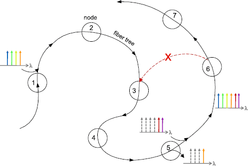
Physical layer architectural rules for filterless optical networks
-
2.
Fiber tree length constraint
The transmission system’s reach sets a maximum distance for any root-leaf combination in a fiber tree. The insertion loss of the passive splitters/combiners must also be taken into account in the link budget, as well as the optical signal-to-noise ratio (OSNR) degradation due to accumulated ASE noise in the optically amplified links. In this work, the maximum fiber-tree length was limited to 1,500 km, which is a realistic reach value for a long haul WDM transmission system. It is assumed that the tunable transceivers are equipped with FEC, as well as digital signal processing modules for CD/PMD/PDL compensation in the electronic domain.
-
3.
The wavelength utilization constraint
The “drop and continue” architecture of the filterless nodes enables multicast applications, but it also limits wavelength reuse. As illustrated in Fig. 4, if a channel has reached its destination and is dropped (channel 4), the signal from this channel (as well as the accumulated ASE noise from upstream) continues downstream. This means that, for wavelength assignment, filterless solutions that minimize the number of wavelengths used must be chosen.

3.2 Genetic and tabu search algorithms
Fiber connection and RWA algorithms have been developed for solving the filterless network design and planning problem. As shown in Fig. 3, the design problem can be solved in two steps: (1) Fiber link interconnection, using a genetic algorithm; (2) RWA, using a tabu search.
In the first step, a fiber connection algorithm is used to interconnect the nodes with optical splitters and combiners. Given the problem’s complexity, a genetic algorithm (GA) adapted from previous work [11] was used to explore the extremely large search space, in order to find optimal, or at least near-optimal, fiber-tree solutions among a population of candidates. Genetic algorithms are heuristics based on the theory of natural evolution. A set of initial feasible solutions of the problem (individuals) is generated by assigning arbitrary colors to the fiber links of the network, forming the initial population. Fitness values are attributed to these candidates, which are based on the network’s total connectivity and the average connection length. Individuals with better fitness are chosen for reproduction, with a mutation factor to randomly modify the genes of an individual, in order to develop the new generation. The primary optimization objective was to obtain network topologies with the desired number of fiber trees and 100 % connectivity between nodes. In this study, a population size varying from 50 to 100 individuals, a mutation ratio around 1 % with a minimum number of 100 generations up to a maximum of 100,000 generations were considered since the convergence is also dependent on the network topology (number of nodes, connectivity, etc.) as well as the secondary objective.
In the second step, routing is performed by selecting the shortest path for each connection. The wavelength assignment process is finally accomplished by considering it as a graph coloring problem with a tabu search metaheuristic adapted from previous work [11]. Routing results are transposed into a conflict graph, where nodes represent the network’s traffic demands. According to the wavelength singularity constraint, conflicts exist between connections when there is at least one common link in their paths, forcing an assignment of different colors (or wavelengths).
3.3 Filterless network design tool
The fiber connection and RWA algorithms developed for solving the filterless network design and planning problem were integrated into a Filterless Network Design and Simulation (FNDS) tool developed in a MATLAB environment. For a given network physical topology and traffic matrix, this tool makes it possible to determine a fiber connection matrix and to perform the RWA for all connection requests.
Various solutions can be obtained, depending on the specific optimization parameters (number of wavelengths, number of fiber trees, number of passive optical dividers, etc.). Table 1 details the optimization parameters considered in this work.
The main network characteristics can be further extracted from the simulation results and used for performance analysis. As a result, the FNDS tool provides filterless network solutions for performance and cost analysis, along with comparisons with other network architectures.
3.4 Filterless link engineering
One advantage of the filterless network architecture is the simplicity of its physical layer. As shown in Fig. 5, filterless nodes and optically amplified links are interconnected with passive power splitters/combiners only [8]. It is further assumed that the λ-tunable transceivers at the terminals are equipped with DSP modules that can offset CD, PMD, and PDL, which further simplifies the link engineering of filterless optical links.

Architecture of filterless links and nodes [8]
In high-speed, multispan, optically amplified links using such transceivers, the accumulated ASE noise generated by the use of inline optical amplifiers in the light trees will be the dominant transmission impairment. Interchannel crosstalk can be another important concern at high optical power levels in long multispan systems. Although linear crosstalk caused by leakage from optical filters and switches can be expected to be reduced in filterless optical links, nonlinear crosstalk due to crossphase modulation (XPM), four-wave mixing (FWM), and Raman crosstalk can affect the quality of the optical signal received [12].
In multispan, optically amplified transmission systems with electronic CD/PMD/PDL compensation, performance is limited by the optical signal-to-noise ratio (OSNR). ASE noise accumulation in optically amplified links (and therefore OSNR) can be easily predicted using an analytical model that could serve to validate the performance of filterless optical links as part of an impairment-aware RWA algorithm and control plane adapted to filterless networks.
Bit error rate (BER) is a fundamental measure of the transmission quality of a digital signal, and the system Q factor is a useful approximation for BER estimation. Waveform distortion and noise effects can be observed in the eye diagram and described using eye penalty factors [12]. Assuming that the thermal and dark current noise at the receiver can be neglected, the Q factor and BER at the end of a filterless optical link can be obtained from Eqs. (1) and (2):
where P ave is the average received power, ℜ is the photodiode responsivity, q is the electron charge, B e and B o are the electrical and optical filter bandwidths respectively, and A and B are the eye opening penalty factors [12]. The ASE noise spectral density ρ ASE can be expressed as:
where n sp is the spontaneous emission factor, h is the Planck constant, G is the optical gain of the amplifier at frequency ν, and the factor 2 indicates two orthogonal polarization states.
The total ASE noise spectral density ρ ASE-TOT at the end of an optically amplified link is given by the sum of the individual ASE contributions (Eq. 4):
A Filterless Link Validator (FLV) tool based on the proposed analytical link model was developed. The objective is to be able to predict the level of ASE noise and signal distortions of a filterless solution in a fast and efficient way by integrating the FLV tool into the Filterless Network Design and Simulation platform, as well as into a filterless control plane. Further details on the implementation are available in [8].
The analytical model was validated using the VPItransmissionMaker TM commercial software tool. Figure 6 shows the VPI model of a wavelength division multiplexing (WDM) optical link, as well as the calculated and simulated BER as a function of distance for a 1,400 km light tree with a 1×2 passive branching node at mid-distance (700 km) showing very good agreement between theoretical and simulated results with A=0.8 % and B=0.7 %.


(a) VPI model of a WDM optical link. (b) Calculated vs. simulated BER as a function of distance for a 1,400 km filterless light tree with 1×2 branching node at 700 km. Link/system parameters: 70 km (14 dB) spans, 8 WDM channels (50-GHz grid), −3 dBm/ch., 6-dB EDFA noise figure [8]
In this section, a filterless analytical link model was proposed as a fast and efficient way to validate the physical layer of filterless optical networks during network design and planning. A Filterless Link Validator prototype was developed in a MATLAB environment and validated with VPItransmissionMaker TM. The results obtained on typical light tree solutions show good agreement between the calculated and simulated BER. The analytical tool could be integrated into the control plane and provide useful performance metrics for network reconfiguration.
4 Proposed filterless solutions for regional and core networks
In this section, filterless network solutions are proposed for a number of physical network topologies as a function of various optimization parameters. The results are compared to active photonic network solutions, in terms of network cost, wavelength utilization, average demand length or average end-to-end path length of the demands (latency), and average number of fiber link segments per demand. These results complement the results presented in a previous study [7] and make it possible to draw interesting conclusions on the design of regional and core filterless networks.
The physical network topologies considered in this performance study are: the 10-node Italian network (15 links, 830 km diameter) [13]; the 17-node Californian network (20 links, 1,027 km diameter) [14]; a modified 8-node COST239 network (12 links, 1,393 km diameter) [15]; the 11-node US network (12 links, 1,924 km diameter).
Figure 7 shows three filterless solutions obtained for the Italian network topology (10 nodes, 15 links, 830 km network diameter), and Fig. 8 shows three filterless solutions for the Californian network topology (17 nodes, 20 links, and 1,027 km network diameter) respectively. The various filterless solutions were obtained by selecting different optimization parameters (see Table 1). Unprotected traffic demands and a uniform traffic matrix between nodes (e.g. one wavelength for every possible connection) were assumed in the simulations. The only physical layer impairment considered in these simulations was the basic system’s reach constraint (1,500 km).


Filterless solutions for the Italian network topology [13]. (a) Solutions (fiber trees represented by different colors). (b) Characteristics of the solutions proposed in (a)


Filterless solutions for the Californian network topology [14]. (a) Solutions (fiber trees represented by different colors). (b) Characteristics of the solutions proposed in (a). (c) Detailed view of solution 2
The three filterless solutions proposed for the 10-node Italian network topology with 2 and 5 fiber trees are shown in Fig. 7. The 2 fiber tree solution (solution 1) is interesting because of its design simplicity. The number of wavelengths required for a uniform traffic matrix (e.g. one wavelength per connection) is 25, which compares well with the number of wavelengths of a corresponding active photonic solution obtained by minimizing demand length (22 wavelengths). The 5 fiber tree solution (solution 2) is interesting, too. Although the wavelength consumption is relatively higher than for the other two solutions (31 wavelengths), this design is characterized by shorter demand lengths (with an average of 436 km), which would be of interest in low latency applications.
Three filterless solutions are proposed for the California network topology (Fig. 8). The 1 fiber tree solution (solution 2) is interesting because of its design simplicity, but at the expense of a greater wavelength consumption (129 wavelengths). The detailed view of solution 2 illustrated in Fig. 8(c) confirms that that the single fiber tree solution does not contain laser loops. The number of wavelengths required in filterless solution 1, for a uniform traffic matrix (e.g. one wavelength per connection), is 120, which is greater than the corresponding active photonic solutions (90 wavelengths, obtained by minimizing demand’s length; 76 wavelengths, by minimizing the number of fiber link segments). Filterless solution 3, with 7 fiber trees and a maximum demand length of 1,337 km, is an interesting solution in terms of latency.
The filterless solutions presented in this study assumed unprotected traffic demands. But, because of the broadcast nature of filterless networks, more than one path can intrinsically exist for routing the traffic between two nodes, which provides a protection path for some of the connection requests. It is interesting to note that the 1+1 protection level (defined here as the ratio of the number of protected demands to the total number of demands in the traffic matrix) was found to vary between 27 and 47 % in the proposed network solutions for the Italian network topology, which can be seen as another interesting attribute of filterless networks. For the Californian network, the 1+1 protection level is lower, with a maximum value of 22 % for the 1 fiber tree solution. Although this aspect has not been explored in this study, it can be assumed that extra traffic protection could be provided through complementary fiber trees, extra capacity built in at nodes or wavelength blockers [7].
Simulations were also performed on physical network topologies with larger diameter size: a modified 8-node COST239 network (1,393 km) [15] and the 11-node US network (1,924 km). The results are summarized in Table 2. As expected, as the network diameter increases, the minimum fiber tree length for ensuring 100 % connectivity between nodes increases to the point where it exceeds the system reach constraint, which means that filterless solutions cannot be found without using regenerator nodes.
The case of the 8-node COST239 network topology (1,393 km network diameter) was studied in more detail. Filterless solutions were obtained by relaxing the system’s reach constraint. The three filterless solutions presented in Fig. 9 are interesting, and compare well with an active photonic switching counterpart. For example, filterless solution 3 (2 fiber trees, 2,081 km maximum fiber tree length, 54 % protection ratio) requires the same number of wavelengths as the active photonic switching solution obtained by minimizing the number of fiber link segments (39 wavelengths) and a smaller number of wavelengths than the active photonic solution obtained by minimizing demand’s length (48 wavelengths).


Filterless solutions for a modified 8-node COST239 network topology [15]. (a) Solutions (fiber trees represented by different colors). (b) Characteristics of the solutions presented in (a)
For network sizes exceeding the system’s reach constraint, the filterless network design method needs to be modified. Figure 10 shows an example of a filterless network solution for a WAN network topology (53 nodes, 1,400 km network diameter) [10]. In this case, the WAN filterless network solution is composed of 3 filterless subnetworks and 4 regenerator nodes located at the boundary of the subnetworks. Details of the method used for designing WAN filterless networks are given in [16].

Example of a filterless network solution (3 filterless subnetworks, 4 regenerator nodes) for a WAN network topology (53 nodes, 1,400 km network diameter) [10]
5 Comparative performance and cost study
In this section, a performance and cost analysis of the filterless solutions proposed in the previous section is presented, along with a comparison with active photonic switching solutions.
Active photonic switching network solutions can be considered as a best-case scenario relative to opaque networks in terms of cost, switching capacity, and latency, as shown in [3, 7]. The active photonic network solutions considered in this study are based on WSS devices, which perform routing on a per wavelength routing basis in the optical domain. In order to achieve full switching capability, we assumed that a WSS was required for every fiber connected to nodes. So, a total of D WSSs were needed at nodes with a node degree D greater than two [17], as illustrated in Fig. 2 for an active photonic switching node of degree 5. Optical amplification (pre and post amplifiers) was also added to compensate for the WSS insertion loss.
A preliminary comparative cost analysis of 3 physical network topologies was presented in previous work [7]. In that exercise, only the passive routing cost (using passive optical splitters/combiners in the filterless case) or the active switching cost (using WSS and associated optical amplifiers in the active photonic solution) were considered in the calculation. The unit cost of the devices (indicated in arbitrary units) can be considered to be fairly representative of their relative cost. The total cost obtained for a network solution is referred to as the “added cost”. The results showed a significant cost advantage for the filterless solutions.
Similar cost calculations were performed on the 8-node COST239 and 17-node Californian network topologies. The results confirm the significant cost savings associated with filterless optical networking.
Table 3 summarizes the network parameters and costs of the filterless and active photonic solutions considered in this study. For this comparative exercise, routing was performed by selecting the shortest path for each demand. This procedure was not completely fair, as active photonic solutions with lower wavelength utilization could be obtained by minimizing the number of fiber link segments, as shown by the numbers in parentheses in Table 2. However, the results show that filterless network solutions compare well with active photonic switching solutions in terms of wavelength utilization.
Wavelength blockers can be added as extra components in a filterless solution, in order to reduce the number of wavelengths needed to meet traffic demands. Simulations carried out on the 7-node German network topology had already shown that the number of wavelengths could be decreased from 105 to 74 by adding 3 wavelength blockers to the network [7]. A similar exercise was performed with the 17-node Californian network topology. In this case, the number of wavelengths required to meet a traffic demand corresponding to a uniform traffic matrix (e.g. one wavelength per connection) could be decreased from 120 to 102 by adding 4 wavelength blockers to the network. These preliminary results are interesting, and show a possible way to decrease wavelength consumption in filterless networks. Further work is required to optimize the number of wavelength blockers and their placement in the network.
6 Conclusions and future work
In this paper, the concept of a filterless network based on advanced transmission technologies and passive optical interconnections between core nodes was presented and explored through a number of filterless optical solutions for different network topologies with diameters ranging from 690 to 1,924 km. The results were obtained using a filterless network design tool based on genetic and tabu search algorithms. Filterless solutions were proposed for a number of physical network topologies and compared with active photonic switching solutions in terms of cost and wavelength consumption. Our results confirm that filterless optical networks represent a cost-effective and reliable alternative to active optical switching network solutions, but at significantly lower cost. Although wavelength consumption in filterless networks is higher than in active photonic switching solutions, the number of wavelengths used in filterless networks can be kept within reasonable limits through optimization, and could potentially be lowered by using a few wavelength blockers. A preliminary filterless solution example based on WAN subdivision into 3 filterless subnetworks has also been proposed, as part of ongoing work on the design of filterless core networks.
Future activities include further study of long haul filterless networks, as well as the refinement of the filterless network design and link engineering tools and the experimental validation of the filterless network concept and its main attributes. Further simulations need to be performed using different traffic schemes and levels, as well as more complex network topologies. Traffic protection and multicast capability are important features of filterless optical networks that need to be further investigated. Network migration and growth, as well as the management requirements for filterless networks, are other aspects to be explored in order to fully demonstrate the robustness and real-world applicability of filterless networks.
References
Youssef, M., Al Zahr, S., & Gagnaire, M. (2011). Translucent network design from a CapEx/OpEx perspective. Photonic Network Communications, 22, 85–97.
Jarray, A., Jaumard, B., & Houle, A. C. (2010, online first). CAPEX/OPEX effective optical network design. Telecommunication Systems.
Tremblay, C., Gagnon, F., Châtelain, B., Bernier, É., & Bélanger, M. (2007). Filterless optical networks: a unique and novel passive WAN network solution. In 12th optoelectronic and communications conference–16th international conference on integrated optics & optical fiber communication (OECC–IOOC 2007) (pp. 466–467). Oxford: IEICE.
McNicol, J., O’Sullivan, M., Roberts, K., Comeau, A., McGhan, D., & Strawczynski, L. (2005). Electrical domain compensation of optical dispersion. In Optical fiber communication conference and exposition and nature fiber optic engineers conference (OFC/NFOEC 2005). Washington: Optical Society of America.
Roberts, K., O’Sullivan, M., Wu, K.-T., Awadalla, A., Krause, D. J., & Laperle, C. (2009). Performance of dual-polarization QPSK for optical transport systems. Journal of Lightwave Technology, 27(16), 3546–3559.
Gumaste, A., & Chlamtac, I. (2003). Light-trails: a novel conceptual framework for conducting optical communications. In Workshop on high performance switching and routing (HPSR 2003) (pp. 251–256).
Archambault, É., O’Brien, D., Tremblay, C., Gagnon, F., Bélanger, M. P., & Bernier, É. (2010). Design and simulation of filterless optical networks: problem definition and performance evaluation. Journal of Optical Communications and Networking, 2(8), 496–501.
Savoie, J.-P., Tremblay, C., Plant, D. V., & Bélanger, M. P. (2010). Physical layer validation of filterless optical networks. In 36th European conference on optical communication (ECOC 2010), Torino, Italy.
Basch, E. B., Egorov, R., Gringeri, S., & Elby, S. (2006). Architectural tradeoffs for reconfigurable dense wavelength-division multiplexing systems. IEEE Journal of Selected Topics in Quantum Electronics, 12(4), 615–626.
Betker, A., Gerlach, C., Hülsermann, R., Jäger, M., Barry, M., Bodamer, S., Späth, J., Gauger, C., & Köhn, M. (2003). Reference transport network scenarios (technical report). BMBF MultiTeraNet project. http://www.ikr.uni-stuttgart.de/IKRSimLib/Usage/Referenz_Netze_v14_full.pdf
O’Brien, D., Châtelain, B., Gagnon, F., Tremblay, C., Bélanger, M. P., & Bernier, É. (2008). A dual metaheuristic solution for the min-RWA problem. In Optical fiber communication conference and exposition and nature fiber optic engineers conference (OFC/NFOEC 2008). Washington: Optical Society of America.
Hui, R., & O’Sullivan, M. (2009). Fiber optic measurement techniques. New York: Academic Press (Chap. 5).
Ali, M. (2005). Routing of 40-Gb/s streams in wavelength-routed heterogeneous optical networks. IEEE Journal on Selected Areas in Communications, 23(8), 1632–1642.
Silvester, J., & Reese, D. (2002). CalREN: towards an optical network. Emeryville: CENIC.
Sinclair, M. C., & O’Mahony, M. J. (1993). COST 239: initial network design and analysis. In 36th RACE concertation meeting, Brussels (pp. 89–94).
Tremblay, C., Enriquez-Castillo, A., Bélanger, M. P., & Gagnon, F. (2011). Filterless WDM optical core networks based on coherent systems. In 13th international conference on transparent optical networks (ICTON 2011), Stockholm, Sweden, June 26–30.
Saleh, A. A. M., & Simmons, J. M. (2006). Evolution toward the next-generation core optical network. Journal of Lightwave Technology, 24(9), 3303–3321.
Acknowledgements
This work is supported by the Natural Sciences and Engineering Research Council (NSERC) of Canada and by Ciena Corporation. The authors acknowledge the contribution of Alfredo Enriquez-Castillo, Daniel O’Brien and Andrew Cassidy to long haul filterless network design algorithms.
Author information
Authors and Affiliations
Corresponding author
Additional information
É. Archambault and J.-P. Savoie were formerly with the École de technologie supérieure, 1100, Notre-Dame Ouest, Montréal, Québec H3P 1Y3, Canada.
Presented at the Asia Communications and Photonics Conference (ACP), Shanghai, China, December 8–12, 2010.
Rights and permissions
Open Access This article is distributed under the terms of the Creative Commons Attribution License which permits any use, distribution, and reproduction in any medium, provided the original author(s) and the source are credited.
About this article
Cite this article
Tremblay, C., Archambault, É., Bélanger, M.P. et al. Passive filterless core networks based on advanced modulation and electrical compensation technologies. Telecommun Syst 54, 167–181 (2013). https://doi.org/10.1007/s11235-013-9725-y
Published:
Issue Date:
DOI: https://doi.org/10.1007/s11235-013-9725-y