
Abstract
We review the surface flux transport model for the evolution of magnetic flux patterns on the Sun’s surface. Our underlying motivation is to understand the model’s prediction of the polar field (or axial dipole) strength at the end of the solar cycle. The main focus is on the “classical” model: namely, steady axisymmetric profiles for differential rotation and meridional flow, and uniform supergranular diffusion. Nevertheless, the review concentrates on recent advances, notably in understanding the roles of transport parameters and – in particular – the source term. We also discuss the physical justification for the surface flux transport model, along with efforts to incorporate radial diffusion, and conclude by summarizing the main directions where researchers have moved beyond the classical model.
1 Introduction
The surface flux transport (hereafter SFT) model is based on an elegant and simple idea, originally formulated by Leighton (1964): radial magnetic flux on the solar surface behaves like a passive scalar field. In other words, flux is carried around by horizontal plasma flows but with no back reaction on these flows.
Despite its simplicity, the SFT model has proven remarkably successful at replicating the magnetic flux patterns on the real solar surface (photosphere). Figure 1 shows an SFT simulation for Solar Cycle 24, where new active regions have been inserted based on magnetograph observations. With appropriate parameters, the time-latitude “magnetic butterfly diagram” in the SFT model (Fig. 1a) is a good match for the observed time-latitude plot (Fig. 1c) at all latitudes. In general, the success of the SFT model has led to important applications both as (i) an inner boundary condition for extrapolations of the magnetic field in the solar atmosphere, and (ii) an outer boundary constraint on models for the solar interior dynamo.

An SFT model for Solar Cycle 24 with emerging regions derived from SDO/HMI SHARPs data (following the method of Yeates 2020). Panel (a) shows the longitude-averaged field \(\langle B_{r}\rangle \) in the simulation, and (b) shows a snapshot of the two-dimensional field \(B_{r}\) on 31 December 2014. For comparison, (c) shows a magnetic butterfly diagram (or super-synoptic map) constructed from SDO/HMI pole-corrected synoptic maps (Sun 2018), smoothed to a comparable resolution to the simulation. The individual, unsmoothed synoptic map for Carrington rotation CR2158 is shown in (d). Red/blue denote positive/negative values, capped at \(\pm 10\,\mathrm{G}\) in (a,c) and \(\pm 50\,\mathrm{G}\) in (b,d)
In this review, our focus is on understanding the model itself: both its key ingredients and fundamental behaviour when applied in the solar regime. Details about applications, particularly to the solar atmosphere, may be found in previous review articles (Sheeley 2005; Mackay and Yeates 2012; Wang 2017). In the solar dynamo context, the SFT model has been used to constrain theories and models of the magnetic field in the solar interior (e.g., Cameron et al. 2012; Cameron and Schüssler 2015; Jiang et al. 2014b; Lemerle and Charbonneau 2017; Whitbread et al. 2019; Hazra 2021). But it is also a valuable practical tool for solar cycle prediction, enabling predictions to be made of the polar field at the end of the current solar cycle, and hence – through well-established correlations – the amplitude of the following solar activity cycle (e.g., Cameron et al. 2016; Iijima et al. 2017; Jiang et al. 2018; Upton and Hathaway 2018; Bhowmik and Nandy 2018; Jiang et al. 2023). Understanding the origin and limitations of such polar field predictions requires an understanding of the SFT model itself, which is what we seek to provide here.
The review is organised as follows. In Sect. 2, we present the basic equations of the “classical” SFT model. Section 3 discusses the imposed flows in the model, including the importance of including meridional flow and recent work on constraining the flow parameters. Section 4 discusses the source term representing new flux emergence, which is fundamental to the flux patterns that the model predicts. Section 5 examines the important question of whether the SFT model – usually seen as purely phenomenological – can be derived from physical principles. We conclude in Sect. 6 with an overview of model features beyond our “classical” version.
2 Fundamentals of the Classical Model
Denoting the radial magnetic field distribution by \(B_{r}(\theta ,\phi ,t)\), the equation for a passive scalar field is
where \({\mathbf{u}}_{h}\) is the imposed advection velocity, and \(\eta \) is the diffusivity. In the classical model, \(B_{r}\) represents the large-scale mean field; the model does not resolve the smaller-scale motions of supergranular convection, but rather models these with the turbulent diffusivity \(\eta \). This was introduced by Leighton (1964) to parameterise the “random walk” of individual magnetic flux elements due to the changing pattern of supergranular flows. For SFT it is necessary to include also a prescribed source term \(S(\theta ,\phi ,t)\) that describes the emergence of new magnetic flux, typically in the form of active regions. In a more complete physical model, \(S\) would arise self-consistently through Faraday’s induction equation (to be discussed in Sects. 5 and 6), but in the classical SFT model it is a prescribed model input. Throughout we will use subscript \(h\) to denote the “horizontal” components of a vector, meaning those tangential to the solar surface.
In the classical SFT model, the diffusivity \(\eta \) is uniform and constant, and most authors assume a steady, axisymmetric imposed velocity of the form
Thus \(\Omega (\theta )\) represents the angular velocity of solar differential rotation, and \(u_{\theta}(\theta )\) represents the meridional circulation. The choice of these flows is important and will be discussed further in Sect. 3. Relaxing the classical assumptions is considered in Sect. 6 (except for the addition of an exponential decay term which is discussed in Sect. 5).
2.1 Dimensionless Form
Ignoring \(S\), we can consider non-dimensionalization of equation (1) by defining dimensionless variables \({\mathbf{u}}'_{h} = {\mathbf{u}}_{h}/U_{0}\), \(\nabla _{h}'=R_{\odot}\nabla _{h}\) and \(t' = tU_{0}/R_{\odot}\), where \(U_{0}\) is a typical flow speed. Then (1) becomes
suggesting that the behaviour (in the absence of new emergence) is controlled by the dimensionless magnetic Reynolds number
In effect, it is only the relative speed of advective to diffusive transport that matters.
2.2 Explicit Form
Writing out (1) explicitly in spherical coordinates, and assuming (2), gives the standard SFT equation
In some applications it suffices to consider the longitude-averaged field,
Integrating (5), we find that \(\langle B_{r}\rangle \) obeys the one-dimensional equation
showing in particular that differential rotation has no effect on the evolution of \(\langle B_{r}\rangle \) (Leighton 1964). On the other hand, the differential rotation – being the fastest flow – plays an important role in determining the two-dimensional flux patterns seen on the solar surface. By increasing the length of the polarity inversion lines in and between active regions, it also speeds up the diffusive cancellation of non-axisymmetric components of \(B_{r}\) (Sheeley and DeVore 1986).
2.3 Implementation
Although some analytical analysis is possible (see Sheeley and DeVore 1986; DeVore 1987, and also Sect. 4 below), for most applications it is usual to solve (5) or (7) with numerical methods. This dates right back to the original paper of Leighton (1964). The most natural numerical approach would be a spectral method based on spherical harmonics, as implemented for example by Mackay et al. (2002) or Baumann et al. (2004) (see Baumann 2005, for more details). However, care is needed in treating the source term \(S\), since newly-emerging active regions are typically highly localized in space and usually require filtering in spectral space to avoid the Gibb’s phenomenon (“ringing”). A more straightforward approach is to use a simple explicit finite-volume method, provided that care is taken in both the discretization and the source term to conserve magnetic flux (i.e., preserve \(\int _{0}^{2\pi}\int _{0}^{\pi }B_{r}(\theta ,\phi ,t)\sin \theta \, \mathrm{d}\theta \mathrm{d}\phi = 0\)). The resulting time-step restriction is typically not a severe problem on modern machines, given the two-dimensional nature and modest resolutions typically used (for example, a \(360\times 180\) mesh). Much higher resolutions would not be consistent with the mean-field assumption of the classical model (alternatives are discussed in Sect. 6).
3 Flows
3.1 Differential Rotation
The solar surface differential rotation is well constrained observationally (see, e.g. Beck 2000) and usually treated as a fixed constraint. Typically, SFT models use a steady axisymmetric angular velocity profile such as
as determined by Snodgrass and Ulrich (1990). The constant term here is written in the Carrington frame that is usually adopted for SFT simulations. The resulting velocity profile is shown in Fig. 2(a). As mentioned above, the differential rotation affects only the non-axisymmetric component of \(B_{r}\), not the axisymmetric component \(\langle B_{r}\rangle \), and will not be discussed further.

Velocity profile of differential rotation in the Carrington frame (a), and some example optimized profiles of meridional flow velocity (b), including (i) the simulation shown in Fig. 1; (ii) the Cycle 21 simulation of Whitbread et al. (2017); and (iii) the Cycle 21 simulation of Lemerle et al. (2015). The corresponding values of \(\Delta _{u}\) are (i) \(0.7\times 10^{-7}\,\mathrm{s}^{-1}\), (ii) \(0.4\times 10^{-7}\,\mathrm{s}^{-1}\), and (iii) \(1.6\times 10^{-7}\,\mathrm{s}^{-1}\)
3.2 Meridional Flow
Although the only large-scale flow included by Leighton (1964) was the differential rotation, it became clear from subsequent investigation of the SFT model that adding a meridional flow gives more realistic magnetic flux distributions (DeVore et al. 1984). In particular, a poleward flow is needed in order to concentrate the magnetic field into polar caps at the end of the solar cycle – compare Figs. 3(a) and (b). Otherwise, once \(B_{r}\) has become approximately axisymmetric it will tend to the slowest decaying (\(\ell =1\)) eigenmode of the diffusion operator, which is the dipole \(B_{r}\sim \cos \theta \). (A pure dipole is not seen in Fig. 3c because it requires a few more years: the decay time for the next higher mode, \(l=2\), is \(R_{\odot}^{2}/[\eta l(l+1)] \approx 6\,\mathrm{yr}\).)

Effect of meridional flow in the simulation from Fig. 1, showing latitude-time plots of \(\langle B_{r}\rangle \) when the flow is included (a) or omitted (b). Panel (c) shows the latitudinal profiles of \(\langle B_{r}\rangle \) at the end of the simulation. The dashed curve shows the (near) steady-state profile (11) for the case with flow. (After Fig. 3 of Sheeley 2005)
Observational evidence now clearly supports the existence of a surface meridional flow (Hanasoge 2022) although it is much slower than the differential rotation and potentially more variable. As such, different modellers have used different flow profiles. Typical examples have a single peak in each hemisphere, but vary in their latitudinal profiles. Figure 2(b) illustrates three profiles: (i) and (ii) come from the simple two-parameter family
where \(\Delta _{u}\) is the flow divergence at the equator, and larger values of \(p\) lead to flows more concentrated near the equator (the speed peaks at \(\cos \theta = \pm (1+p)^{-1/2}\)). Profile (iii) in Fig. 2(b) has the more complex form
which allows the gradient to be concentrated nearer to the equator (see Wang 2017).
It is non-trivial to determine the precise eigenmodes of equation (7) when meridional flow is included (DeVore 1987), even with a simple flow profile such as (9). However, one can determine a useful approximation by seeking a perfectly axisymmetric steady state \(B_{r}(\theta )\) that balances the poleward advection with diffusion. For example, for the flow profile (9), equation (7) can be solved in an individual hemisphere to give the steady state solution
Here \(\mathrm{Rm}_{0} = R_{\odot}^{2}\Delta _{u}/\eta \), which is the magnetic Reynolds number \(\mathrm{Rm}\) from (4) with the specific choice \(U_{0} = R_{\odot}\Delta _{u}\), highlighting explicitly the dependence of the solution on the magnetic Reynolds number. The amplitude \(B_{r}(0)\) will depend on the initial condition and source term \(S\) and cannot be determined directly. The solution (11) can only be an approximation to the slowest-decaying eigenfunction because it is necessarily non-zero at the equator, and will therefore generate a discontinuity at the equator when applied in both hemispheres with opposite sign. However, this discontinuity is small for typical values of \(\mathrm{Rm}_{0}\) and will lead to diffusive cancellation only on a timescale much longer than the solar cycle (cf. Cameron et al. 2010). Indeed, Fig. 3(c) shows that (11) gives an excellent approximation to the latitudinal \(B_{r}\) profile at the end of the example simulation in Fig. 3(a), particularly in the Northern hemisphere. (In the Southern hemisphere there is a remnant active region at low latitude that modifies the profile.) This simulation used \(\eta =425\,\mathrm{km}^{2}\mathrm{s}^{-1}\), \(p=3.87\), \(\Delta _{u}=6.9\times 10^{-8}\,\mathrm{s}^{-1}\), and consequently \(\mathrm{Rm}_{0}\approx 79\).
3.3 Parameter Optimization
The primary flow parameters to choose are the meridional flow profile \(u_{\theta }(\theta )\) and the diffusivity coefficient \(\eta \). The basic effects of varying these parameters were investigated in the 1980s (DeVore et al. 1984; Wang et al. 1989). A more systematic parameter study was published by Baumann et al. (2004), who explored the results of varying both \(\eta \) and the meridional flow amplitude (in addition to properties of the source term), albeit varying only one parameter at a time and not the shape of the meridional flow profile.
More recent studies have explored the parameter space more widely, and have also attempted to optimize the parameters directly against synoptic magnetogram observations. The two most general studies are Lemerle et al. (2015) and Whitbread et al. (2017), who both allow the strength and shape of \(u_{\theta}(\theta )\) to vary, in addition to \(\eta \). For \(u_{\theta}\), Whitbread et al. (2017) allowed for profiles of the form (9), whereas Lemerle et al. (2015) allow for the more general (but still single-peaked) form (10). The optimal profiles from both studies for data from Cycle 21 are shown in Fig. 2. At present, it is not possible to select confidently between these solutions using observations, though helioseismic measurements of the plasma flow suggest equatorial slopes \(\Delta _{u}\) in the range \([0.6-1.2]\times 10^{-7}\,\mathrm{s}^{-1}\) – somewhere between profiles (i) and (iii) in Fig. 2. Measurements based on magnetic feature tracking give lower equatorial slopes more like that of profile (ii), but it has been suggested that these are contaminated by supergranular diffusion (Dikpati et al. 2010; Wang 2017). A recent list of observations is given in Jiang et al. (2023).
Both Lemerle et al. (2015) and Whitbread et al. (2017) used the same genetic optimization algorithm, PIKAIA (Charbonneau and Knapp 1995). These two studies differed in their chosen goodness-of-fit functions, although both were ultimately derived from comparing to observed \(B_{r}(\theta ,\phi )\) maps. Whitbread et al. (2017) gave more weight to lower latitudes (where magnetogram observations are more reliable), whereas Lemerle et al. (2015) gave additional weight to the mid-latitude “transport regions” (because they represent the result of the model evolution rather than only the active region emergence) and to the axial dipole strength. At the other extreme, a further parameter study by Petrovay and Talafha (2019) focused only on optimizing the high latitude (polar) field, albeit in the 1D model. This study used a synthetic (averaged) source term and fitted to average cycle properties from Wilcox Observatory polar field measurements, such as reversal time or width of the polar cap.
A robust finding in these optimization studies is a degeneracy between \(\eta \) and the amplitude of \(u_{\theta}\). This is illustrated by Fig. 4, which shows that there is a long ridge of near-optimal solutions in parameter space. Increasing both parameters together tends to lead to a equally (or nearly equally) well-matched solution, perhaps explaining why different groups have been able to use quite different values of \(\eta \) – for example, Cameron et al. (2010) use \(\eta =250\,\mathrm{km}^{2}\mathrm{s}^{-1}\) as their standard value whereas the simulation in Fig. 1 used \(\eta =425\,\mathrm{km}^{2}\,\mathrm{s}^{-1}\). This degeneracy makes sense given the appearance of the magnetic Reynolds number \(\mathrm{Rm}\) in equation (3), which is essentially the ratio of \(\eta \) to \(\lvert u_{\theta}\rvert \). It means that SFT simulations can not be used to constrain both the meridional flow and diffusion from magnetogram observations alone.

Fitness function \(\chi ^{-2}\) as a function of meridional flow amplitude \(u_{0}=\max _{\theta}\lvert u_{\theta}\rvert \) (horizontal axis) and diffusivity \(\eta _{\mathrm{R}}\equiv \eta \) (vertical axis), from the optimization study of Lemerle et al. (2015). Black lines show the optimum value and blue lines the limit of the acceptable region (\(\chi ^{-2}\geq 93 \%\chi ^{-2}_{ \mathrm{max}}\)). (© AAS. Reproduced with permission.)
When optimizing the model individually for different solar cycles, Whitbread et al. (2017) found some cycle-to-cycle variation in the optimal speeds and diffusivities. This is understandable given the phenomenological nature of the model (to be discussed further in Sect. 5). Indeed, when simulating multiple cycles, Wang et al. (2002) had previously varied the meridional flow speed from cycle to cycle so as to avoid unrealistic drift of the polar field over time. On the other hand, other authors have avoided this problem by varying instead the tilts of emerging active regions (Cameron et al. 2010, see also Sect. 4.3), or adding an addition decay term (to be discussed in Sect. 5). In reality it is likely that the effective mean-field meridional flow varies even over the course of a single Solar Cycle (see Sect. 6). Interestingly, Hung et al. (2017) have shown – in the context of a flux-transport (interior) dynamo model – that a time-dependent meridional flow may be recovered from surface magnetic data through variational data-assimilation, and in future this approach could also be applied to SFT.
4 The Source Term
The magnetic flux patterns in the SFT model are determined in large part by the source term \(S(\theta ,\phi ,t)\), which – in the classical mean-field model – represents the emergence of new macroscopic active regions on the solar surface. Since the classical SFT equation (1) is linear in \(B_{r}\), the solution is a superposition of solutions for each individual active region, so it is insightful to consider the evolution of one of these regions in isolation. Since most SFT simulations follow the evolution for periods of years, it is usual to emerge each active region instantaneously in time, so that
where \(B_{r}^{(i)}(\theta ,\phi )\) is the magnetic field of an individual active region emerging at \(t=t^{(i)}\).
Traditionally, SFT models treat each active region as a bipolar magnetic region (BMR). Figure 5 shows the shape used by Van Ballegooijen et al. (1998), with circular flux patches centred on the poles \((\theta _{-},\phi _{-})\) and \((\theta _{+},\phi _{+})\) and having the form
where
Thus \(\beta _{\pm}(\theta ,\phi )\) denote the heliocentric angles from each pole, and \(\rho _{0}\) the heliocentric angle between them. Van Ballegooijen et al. (1998) took \(b=0.4\). For some purposes, one can approximate (13) with a pair of Dirac-delta sources,
where \(\Phi _{0}\) gives the flux of each polarity, defined assuming flux balance as

Although the precise chosen shape for BMRs varies between implementations (see Yeates 2020, for another variation), the key properties are the magnetic flux, \(\Phi _{0}\), and pole locations, \((\theta _{-},\phi _{-})\) and \((\theta _{+},\phi _{+})\). The latter may equivalently be specified by giving the coordinates of the BMR centre \((\theta _{0},\phi _{0})\) along with the separation \(\rho _{0}\) as in (15) and tilt angle \(\gamma _{0}\), typically defined by
Together these BMR properties determine both the short-term and long-term evolution of the region.
After a new region emerges in the model, much of its magnetic flux cancels by supergranular diffusion. This models the observed process of flux cancellation at the polarity inversion line (PIL) between the positive and negative polarities. This cancellation rate is enhanced as the region is sheared by differential rotation and the PIL lengthened. On short-timescales (days) it is possible to approximate the solar surface as a Cartesian plane. Assuming a linear shear flow profile for the differential rotation, Lagrangian variables can be used to solve the Cartesian form of (1) for the exact evolution \(B_{r}(\theta ,\phi ,t)\) of a tilted BMR (we will see an example in Sect. 4.1). On longer timescales, it is necessary to follow the evolution numerically.
It takes approximately 2 years for the non-axisymmetric component of \(B_{r}\) to cancel completely (Wang and Sheeley 1991). Whether or not any axisymmetric \(B_{r}\) remains on a longer timescale depends on how much flux of one polarity escapes across the equator so that the two polarities are pushed to opposite poles by the meridional flow. An untilted region will send both polarities equally to each pole and so leave no asymptotic contribution at the end of the solar cycle. In a similar way, a (tilted) region that is nearer to the equator will produce a greater asymptotic contribution, because more flux escapes across the equator before being cancelled. This important effect is illustrated in Fig. 6, where the same BMR is inserted at three different latitudes.

Long term evolution of three identical BMRs emerged at different latitudes (\(\lambda _{0} = \pi /2 - \theta _{0}\)) in the SFT model. Left column shows the initial BMRs and right column the time-latitude plot of \(\langle B_{r}\rangle \) in each case
4.1 Dipole Amplification Factor of a BMR
A common way to measure the end-of-cycle contribution of an individual BMR is through its axial dipole strength, which is the axisymmetric spherical harmonic coefficient of \(B_{r}\) with lowest degree,
By linearity of the classical SFT model, the total axial dipole strength will be the sum of the individual contributions from all of the active regions.
At the time of emergence, a BMR with the simple form (16) has
Here we have defined the central colatitude \(\theta _{0}=(\theta _{+}+\theta _{-})/2\) and recognized that for tilt angle \(\gamma _{0}\) and heliocentric angle \(\rho _{0}\) between the poles, their latitudinal separation is \((\theta _{+}-\theta _{-})=\rho _{0}\sin \gamma _{0}\) (assuming \(\theta _{+}>\theta _{-}\)). Thus, as noted by Wang and Sheeley (1991), the axial dipole strength of a newly-emerged BMR depends on its flux, its latitudinal pole separation, and the cosine of its emergence latitude.
Importantly, the axial dipole strength of a BMR can change under the ensuing SFT evolution: it will be amplified if the BMR emerged near the equator, or will decay if the BMR emerged far from the equator. It was first recognized by Jiang et al. (2014a) that the “dipole amplification factor”
is well approximated by a Gaussian function of latitude, of the form
where \(\lambda _{0}=\pi /2 - \theta _{0}\) is the central latitude of the BMR. (It is convenient to work in terms of latitude \(\lambda =\pi /2 - \theta \) rather than colatitude \(\theta \).) Fig. 7 shows the functional form measured in several different numerical SFT models, where we note that both the amplitude \(A\) and width \(\lambda _{R}\) depend on the model. Once these parameters are known, equation (25) – coupled with the linearity of the SFT evolution equation (5) or (7) – allows the net axial dipole strength at the end of a solar cycle to be determined algebraically just by adding up the contributions of the individual BMRs, without the need to solve the evolution equation.

Latitude dependence of the dipole amplification factor for BMRs in different published SFT models. The solid lines show Gaussian fits. Reproduced from Petrovay et al. (2020)
The interpretation of Fig. 7 is that only BMRs that emerge with latitude \(\lvert \lambda _{0}\rvert <\lambda _{R}\) will contribute to the global dipole moment at the end of the solar cycle. Petrovay et al. (2020) call \(\lambda _{R}\) the “dynamo effectivity range”, and give the following simple physical derivation. To give a lasting contribution, a BMR must be close enough to the equator that some of its leading-polarity flux is able to cross the equator by diffusion, in opposition to the meridional flow. The timescale for advective separation at the equator is \(\Delta _{u}^{-1}\), where \(\Delta _{u}=R_{\odot}^{-1}u_{\theta}'(\pi /2)\) is the equatorial divergence of \(u_{\theta}(\theta )\). Equating this to the diffusion timescale \((\lambda R_{\odot})^{2}/\eta \) from latitude \(\lambda \) to the equator suggests that
Note the reappearance of the magnetic Reynolds number from Sect. 3.2. Petrovay et al. (2020) computed \(f_{\infty}(\lambda _{0})\) for numerical solutions with several different \(u_{\theta}\) profiles, and in most cases found that the Gaussian width \(\lambda _{R}\) was indeed well approximated by \(\mathrm{Rm}_{0}^{-1/2}\), the exception being a flow where \(u_{\theta}\) peaks at a very low latitude compared to observations.
Petrovay et al. (2020) went further and derived (25) analytically. (Readers not interested in the details may skip to Sect. 4.2.) The trick is to recognize that the final dipole moment – once the \(B_{r}\) distribution has become (near) axisymmetric – will be proportional to the remaining net magnetic flux in each hemisphere. (There will also be a coefficient depending on the latitudinal profile of the near-steady state as in (11).) Because it is determined purely by flux crossing the equator, the evolution of the net hemispheric flux can be quite well approximated by a Cartesian SFT model near the equator, which has the advantage of being analytically tractable. Thus Petrovay et al. (2020) consider the “low-latitude limit” of (7),
By choosing the linearised meridional flow \(u_{\lambda }= R_{\odot}\Delta _{u}\lambda \), we can define the Lagrangian coordinate \(\ell = \mathrm{e}^{-\Delta _{u} t}\lambda \) and new time variable \(\tau = \left (1 - \mathrm{e}^{-2\Delta _{u} t}\right )/(2\mathrm{Rm}_{0})\) to reduce Equation (27) to a standard diffusion equation
where \(\mathrm{D}/\mathrm{D}\tau \) denotes the partial derivative with \(\ell \) kept constant rather than \(\lambda \). Equation (28) may be solved for a variety of initial conditions using standard techniques.
If the initial condition consists of a single (monopole) point source,
then solving (28) gives
which for large \(t\) is approximately
In the approximation (31), the flux difference between the hemispheres is
valid for either sign of \(\lambda _{0}\).
For a BMR we must combine two point sources as in (16), each contributing half of the flux \(\Phi _{0}\), so
where we recognize the finite difference as an approximation of the derivative at \(\lambda _{0} = (\lambda _{-}+\lambda _{+})/2\). We therefore expect that, to a good approximation, \(b_{1,0}(t) \to a(\Phi _{\mathrm{N}} - \Phi _{\mathrm{S}})/R_{\odot}^{2}\) as \(t\to \infty \), for some constant \(a\) that depends on the (normalized) shape of the steady \(B_{r}\) profile (thus only on \(u_{\theta}\) and \(D\)). At the initial time, Equation (23) gives \(b_{1,0}(0) = 3\Phi _{0}(\lambda _{+} - \lambda _{-})\cos \lambda _{0}/(4 \pi R_{\odot}^{2})\). Approximating \(\cos \lambda _{0}\approx 1\), the ratio is therefore
Thus we recover (25) with \(\lambda _{R} = \mathrm{Rm}_{0}^{-1/2}\) as claimed. Moreover, for a known asymptotic profile of \(B_{r}(\theta )\), we can determine \(a\) and hence also predict the amplitude \(A\).
4.2 Non-bipolar Source Regions
Real solar active regions cannot always be represented as simple, symmetric BMRs. Even a region with two polarities will be effectively “multipolar” if the polarities are asymmetric in shape, and this will modify the evolution of \(b_{1,0}\) compared to a symmetric BMR. This was investigated by Iijima et al. (2019), who ran SFT simulations with Gaussian BMRs of the form (13), but where the leading polarity has a narrower width than the following polarity (controlled by the \(b\) parameter in (13)). When calibrated to the observed level of sunspot area asymmetry, their SFT simulation gave a more realistic evolution of both \(b_{1,0}\) and the magnetic butterfly diagram, as compared to a reference simulation with equally-sized polarities. In particular, they noted that a wider following polarity leads to more following polarity flux crossing the equator, cancelling some of the trans-equatorial leading polarity flux and weakening the asymptotic contribution of the region. Similarly, Wang et al. (2021) found for asymmetric BMRs with more diffuse following polarity, that \(f_{\infty}\) is systematically reduced (see their Fig. 4). As an illustration, Fig. 8 shows an example of the SFT evolution for an asymmetric region inserted directly with its observed shape; in this case, the effect is sufficiently extreme to reverse the sign of \(b_{1,0}\) altogether compared to a symmetric BMR.

Evolution of an active region with asymmetric bipolar shape, taken from the simulation in Fig. 1. The left column shows the region with its observed shape, with second row showing \(\langle B_{r}\rangle \) and third row the axial dipole strength \(b_{1,0}\). The right column shows the evolution of an “equivalent” symmetric BMR having the same initial flux and \(b_{1,0}\). The dashed line shows the final \(b_{1,0}\) predicted by equation (36) using the observed magnetogram
Jiang et al. (2019) considered the SFT evolution of a more complex “\(\delta \)-type” flux distribution. They showed that \(b_{1,0}\) changed sign during the SFT evolution, ending up with a completely different end-of-cycle contribution than would be expected for a BMR emerging at the same latitude with the same flux and same initial \(b_{1,0}\). Wang et al. (2021) showed further that the dipole amplification \(f_{\infty}\) is no longer a simple function of emergence latitude for such complex regions. However, the net effect of all of the real complex and asymmetric regions seems to be a reduction in the net end-of-cycle dipole, at least for Cycle 24. Evidence for this comes from Yeates (2020), who compared an SFT simulation of that cycle where all active regions emerged with their observed flux distributions to a simulation where they were all approximated by symmetric BMRs with the same flux and initial \(b_{1,0}\). The net \(b_{1,0}\) at the end of the cycle was overestimated by 24% when the regions were modelled with BMRs.
For predicting the dipole contributions of more complex regions, Wang et al. (2021) showed that (35) can be generalized to regions with non-bipolar shapes, by treating them as a superposition of point sources. In particular, for an active region with initial flux distribution \(B_{r}(\theta ,\phi ,0)\), combining the hemispheric flux differences (32) predicts that the axial dipole strength at the end of the cycle would be
where \(a\) is the coefficient in the relation \(b_{1,0}\approx a(\Phi _{\mathrm{N}}-\Phi _{\mathrm{S}})/R_{\odot}^{2}\). Wang et al. (2021) verified this prediction against SFT simulations for 84 regions during Cycle 24. It gives an accurate prediction for the region in Fig. 8.
4.3 Modelling the Source Term
It is not always viable to use observations of real individual active regions to construct the source term. This situation arises when working with historical data, when running SFT models into the future for forecasting purposes, or just in conceptual simulations studying the underlying physics. In such cases the source term \(S(\theta ,\phi ,t)\) needs to be modelled, either as a smooth function (e.g., Cameron and Schüssler 2007; Petrovay and Talafha 2019) or as random realizations of active regions drawn from a statistical distribution (e.g., Schrijver 2001; Mackay and Lockwood 2002; Baumann et al. 2004; Jiang et al. 2018; Wang and Lean 2021).
The smooth function approach has primarily been used in the 1D SFT model, (7), for example by Petrovay and Talafha (2019), who use a pair of flux rings in each hemisphere, shown in Fig. 9(a) and given by
This model incorporates a number of observed solar cycle features:
-
(i)
All polarities alternate according to the solar cycle number, \(n\).
-
(ii)
The cycle has an asymmetrical shape in time, shown in Fig. 9(b) and given by the Hathaway et al. (1994) observed fit
$$ A(t) = a(t-t_{\mathrm{min}})\left (\exp \left [ \frac{(t-t_{\mathrm{min}})^{2}}{b^{2}}\right ] - c\right )^{-1}, $$(38)where \(t_{\mathrm{min}}\) is the start of the cycle.
Fig. 9 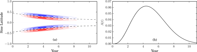
The smooth source term \(\langle S\rangle (\lambda ,t)\) used by Petrovay and Talafha (2019). In (a), red/blue contours show \(\langle S\rangle \), and dashed lines indicate \(\pm \sin [\lambda _{0}(t)]\) from (39). Panel (b) shows the overall cycle shape \(A(t)\) from (38) with \(a=0.00185\), \(b=4.058\), \(c=0.71\)
-
(iii)
The centres \(\pm \lambda _{0}\) of each pair of flux rings, i.e. \(\lambda _{0} = (\lambda _{+} + \lambda _{-})/2\) shown by dashed lines in Fig. 9(a), migrate equatorward at the rate
$$ \lambda _{0}(t) = 26.4 - 34.2\left (\frac{t}{T}\right ) + 16.1 \left ( \frac{t}{T}\right )^{2}\quad [^{\circ}] $$(39)fitted empirically by Jiang et al. (2011), where \(T\) is the cycle length (11 years).
-
(iv)
The separation \(\Delta _{\lambda }= \lambda _{-}-\lambda _{+}\) decreases as \(\lambda _{0}\) approaches the equator, according to
$$ \Delta _{\lambda}(t) = 0.5 \frac{\sin \lambda _{0}(t)}{\sin 20^{\circ}} \quad [^{\circ}]. $$(40)This models the longitude-averaged effect of the well-established Joy’s Law (van Driel-Gesztelyi and Green 2015), whereby BMRs emerging at lower latitude have (on average) smaller tilt angle \(\lvert \gamma _{0}\rvert \), defined in (18).

The statistical BMR approach is similar, except the functions above are treated as overall distributions from which discrete BMRs are chosen at random. For the longest historical simulations, which date back to 1700 (Jiang et al. 2018; Wang et al. 2021), the only observational input is the sunspot number time series – equivalent to emergence rate, \(A(t)\). For 20th Century simulations, data on the areas and locations of individual sunspot groups can be used (e.g., Cameron et al. 2010). However, even here the magnetic flux and tilt angle (equivalently axial dipole strength) must be chosen at random as they are not available observationally before the onset of routine magnetograms in the 1970s.
The tilt angle is problematic as Joy’s Law, as modelled in (40), holds only for the mean, and there is known to be very significant scatter (e.g., Wang and Sheeley 1989; Yeates 2020). Recent studies have shown that individual “rogue” active regions – defined as those with dipole moments significantly different from Joy’s Law expectation at their latitude – can have a significant effect on the overall polar field at the end of the cycle (Jiang et al. 2015; Nagy et al. 2017). In light of (35), such rogue regions must typically emerge near to the equator, although their relative contribution depends on \(\mathrm{Rm}_{0}\) and would be reduced if \(\mathrm{Rm}_{0}\) were large. Nevertheless, simulations based on statistical source terms without individual dipole moment data should be treated with caution, particularly for prediction.
The widely-accepted \(\alpha \Omega \) paradigm for the solar dynamo suggests a “self-consistent” way to build a fully synthetic SFT model: set the amount flux emerging through the source term in cycle \(n\) proportional to the axial dipole strength at the end of cycle \(n-1\). Talafha et al. (2022) modified the one-dimensional model of Petrovay and Talafha (2019) to use such an approach. They used this model to systematically study the impact of two possible nonlinearities in the source term: tilt quenching (where BMRs are less tilted in strong cycles) and latitude quenching (where BMRs emerge at higher latitudes in strong cycles). SFT simulations show that both effects act to reduce the axial dipole produced in strong cycles (Cameron et al. 2010; Jiang 2020). They are both therefore possible saturation mechanisms to explain why the solar dynamo doesn’t exhibit runaway exponential growth. Talafha et al. (2022) showed that the relative impact of tilt versus latitude quenching on the end-of-cycle axial dipole depends primarily on the dynamo effectivity range \(\lambda _{R}\) in equation (26). In particular, for small \(\lambda _{R}\), latitude quenching reduces the end-of-cycle dipole more than tilt quenching, and vice versa for large \(\lambda _{R}\). However, the amount of tilt and/or latitude quenching present on the real Sun remains under debate.
5 Physical Justification
As introduced by Leighton (1964), the SFT model is purely phenomenological. But can equation (1) be derived from known physical laws? The relevant law governing the evolution of the large-scale magnetic field is the mean-field MHD (magnetohydrodynamic) induction equation,
where \({\mathbf{u}}\) is the plasma velocity and – anticipating the form of (1) – we have made a simple approximation for the turbulent electromotive force of the form \(-\eta \nabla \times{\mathbf{B}}\) (cf. McCloughan and Durrant 2002). Thus \(\eta \) represents turbulent diffusivity, not ohmic resistivity (which is negligible in the highly conducting photosphere). This assumption of a turbulent diffusivity is discussed further in Sect. 5.3 below.
Consider the first term in (41). Decomposing \({\mathbf{u}}={\mathbf{u}}_{h} + u_{r}{\mathbf{e}}_{r}\), where \({\mathbf{e}}_{r}\cdot{\mathbf{u}}_{h}=0\), and similarly \({\mathbf{B}}={\mathbf{B}}_{h} + B_{r}{\mathbf{e}}_{r}\), we can write
The last term is precisely the advection term in the SFT equation (1), while the term \(\nabla \cdot \big(u_{r}{\mathbf{B}}_{h}\big)\) represents flux emergence, so corresponds to the source term \(S\) in (1). Thus the SFT model is incorporating the correct advection terms.
Now consider the diffusion term in (41). For simplicity, we will assume that \(\eta =\eta (r)\) only, in which case
This has the diffusion term from (1) plus an additional remainder term
Using \(\nabla \cdot{\mathbf{B}}=0\), this may be rewritten entirely in terms of \(B_{r}\), simplifying to
Thus in mean-field MHD there is an additional term representing the radial diffusion of magnetic flux that is missing from the original SFT equation (1). Physically, this incorporates the fact that the surface magnetic field is connected to the interior; for example, the decay of active regions can be slowed if they remain connected to deeper layers of the convection zone where the diffusivity is lower (Wilson et al. 1990; Whitbread et al. 2019).
One way to justify the classical SFT model is to assume that \(B_{\theta }, B_{\phi }\approx 0\) in the near-surface region of the solar convection zone. It then follows from (44) that \(R_{\eta }=0\). To some extent this is justified by vector magnetogram observations at the photosphere (for a recent discussion, see Virtanen et al. 2019; for a theoretical argument, see van Ballegooijen and Mackay 2007). If this radial-field approximation is not made, then self-consistent computation of the radial diffusion term \(R_{\eta}\) would require simulation of the three-dimensional magnetic field in the solar convection zone. However, two approaches have been used to parametrize (45) in SFT models without the need for three-dimensional simulations, and these will be considered next.
5.1 Exponential Decay Term
The most common parametrization for the radial diffusion term (45) is to assume that \(R_{\eta}\approx - B_{r}/\tau \), so that (1) becomes
Multiplying by \(\mathrm{e}^{t/\tau}\) shows that
Thus if \(B_{r}^{\infty}\) denotes the solution to the original equation (1), corresponding to \(\tau \to \infty \), then the solution with finite \(\tau \) but all other parameters the same is \(B_{r} = \mathrm{e}^{-t/\tau}B_{r}^{\infty}\). In other words, the solution decays exponentially at uniform rate \(\tau ^{-1}\). For example, the dipole amplification factor (35) for a BMR would become
reflecting continuing decay of the magnetic field due to the new term.
The first application of such a decay term was by Schrijver et al. (2002), who motivated it not by consideration of radial diffusion but purely as a necessary addition to reduce the “memory” of the polar field (equivalently \(b_{1,0}\)) over multiple solar cycles. Without it, the varying amount of polar field production caused by the differing sunspot numbers in different cycles led to an unrealistic drift in the polar field over time, rather than the regular reversals that are observed. This drift is illustrated (for another SFT model) in the top panel of Fig. 10.

Application of the radial diffusion term to reduce spurious cycle-to-cycle memory in the SFT model, from Baumann et al. (2006). The top row shows the north polar field (above \(75^{\circ}\) latitude) in a simulation with no radial diffusion, while the middle and bottom rows show the same simulation with \(\eta _{0}=50\,\mathrm{km}^{2}\mathrm{s}^{-1}\) and \(100\,\mathrm{km}^{2}\mathrm{s}^{-1}\) according to the prescription in Sect. 5.2. The simulation uses random emerging BMRs proportional to the observed sunspot numbers. The dashed line shows a simulation started in 1750, illustrating how the memory of the initial conditions persists. (© ESO. Reproduced with permission.)
The optimization studies discussed in Sect. 3 have also looked for the optimum \(\tau \) in shorter simulations where long-term memory is not an issue. With their simplified source term, Petrovay and Talafha (2019) found that a decay term (with \(\tau \) in the range 5–10 yr) was essential, otherwise \(b_{1,0}\) reversed too late for all of the flow profiles and parameters tried. And in simulations of Cycle 23 driven by idealised BMRs, Whitbread et al. (2017) found that a decay term with \(\tau < 5\text{ yr}\) helped to reduce unrealistically high values of \(b_{1,0}\). However, they found that emerging active regions with observed shapes reduced \(b_{1,0}\) in itself (as did Yeates 2020, for Cycle 24), and the optimization did not strongly select for a particular \(\tau \). Moreover, the fit of the optimum model did not improve significantly when the decay term was included in the model compared to when it was not. Lemerle et al. (2015) also found that \(\tau \) was not strongly constrained by the optimization process, with acceptable solutions found for suitable parameter combinations with \(\tau \) in the range from 7–32 yr. In summary, the presence of a decay term as required by Schrijver et al. (2002) does not seem to be ruled out by observations.
It should be noted that, in principle, an additional decay term is not the only way to reduce the cycle-to-cycle memory of \(b_{1,0}\) in the model. Alternatives that have been adopted include imposed cycle-to-cycle variations in either the meridional flow speed (Wang et al. 2002) or the tilt angles of emerging BMRs (Cameron et al. 2010). It is difficult to choose definitively between these options with only about four solar cycles of full magnetogram observations.
5.2 Diffusive Interior Model
An improved parametrization for (45) was suggested by Baumann et al. (2006). They observed that if one assumes a purely diffusive evolution with uniform diffusivity \(\eta =\eta _{0}\) throughout the convection zone, then the term \(R_{\eta}\) may be approximated using only \(B_{r}\) on the solar surface.
Specifically, Baumann et al. (2006) consider a purely poloidal field \({\mathbf{B}} = \nabla \times \nabla \times \big({\mathbf{r}}P\big)\) inside the convection zone \(R_{\mathrm{b}}< r< R_{\odot}\), with boundary conditions \(B_{r}(R_{\mathrm{b}},\theta ,\phi )=0\) and \(B_{\theta}(R_{\odot},\theta ,\phi )=B_{\phi}(R_{\odot},\theta ,\phi )=0\). Under a purely diffusive decay
with \(\eta _{0}\) constant, and a suitable gauge choice for \(P\), this reduces to the scalar problem
The solution, omitting the monopole term, may be written as an expansion
where \(Y_{l}^{m}\) are spherical harmonics and \(j_{l}\), \(y_{l}\) are spherical Bessel functions of the first and second kinds. Linearity of (50) allows Baumann et al. (2006) to set \(a_{l,n}=1\) without loss of generality, so the inner boundary condition fixes the other coefficient
The upper boundary condition then gives
This equation must be solved numerically for each \(l\) and \(n\) to determine the eigenvalues \(k_{l,n}\), which give the decay times \(\tau _{l,n} = (\eta _{0} k_{l,n}^{2})^{-1}\) for each component, where \(l\) is the spherical harmonic degree and \(n\) is the radial mode number. Since the SFT model does not give the subsurface radial structure, Baumann et al. (2006) propose to keep only the modes with \(n=0\), which are the slowest decaying modes for each \(l\). They modify the SFT equation (1) to
where \(b_{l,m}(t)\) are the spherical harmonic coefficients in the expansion of \(B_{r}\),
The interior diffusivity \(\eta _{0}\) that determines \(\tau _{l,0}\) is taken to be different from the coefficent \(\eta \) of the classical diffusion term.
Note that, since radial modes with \(n>0\) are neglected, the effect on \(b_{1,0}\) is identical to the simple exponential decay term, with \(\tau = \tau _{1,0} = (\eta _{0} k_{1,0}^{2})^{-1}\). Accordingly, Baumann et al. (2006) showed that their alternative form of the decay term can also reduce the spurious long-term memory of the SFT model, as illustrated in the middle and bottom rows of Fig. 10. They found that diffusivity values in the range \(\eta _{0}=50-100\,\mathrm{km}^{2}\mathrm{s}^{-1}\) gave polar field evolutions consistent with recent observations. For \(R_{\mathrm{b}}=0.7R_{\odot}\), and since \(k_{1,0}\approx 5.46\), this corresponds to decay times for \(b_{1,0}\) in the range \(\tau _{1,0}\approx 5-10\,\mathrm{yr}\). In their model driven by idealized BMRs, Whitbread et al. (2017) found an optimum \(\eta _{0}=190\,\mathrm{km}^{2}\mathrm{s}^{-1}\), giving a decay time \(\tau _{1,0}=2.7\,\mathrm{yr}\), in agreement with the \(\tau \) found by optimizing the simple exponential decay term. Virtanen et al. (2017) also adopted the Baumann et al. (2006) model, but in a simulation where active regions had observed shapes; they found a value \(\eta _{0}=100\,\mathrm{km}^{2}\mathrm{s}^{-1}\) to give reasonable results.
It is worth remarking that these implementations of (54) have used different diffusivities for \(\eta \) (the classical horizontal diffusion) and \(\eta _{0}\) (which determines \(\tau _{l,0}\)). Moreover, the extra term in (54) includes both radial and horizontal diffusion due to the interior diffusivity \(\eta _{0}\). If one evaluates the radial diffusion term (45) for a single mode of the interior solution (51), one obtains
giving a decay time \(\tau _{l,n}'= \eta _{0}^{-1}[k_{l,n}^{2} - l(l+1)/R_{\odot}^{2}]^{-1}\) for radial diffusion alone. However, for small \(l\) the difference from \(\tau _{l,n}\) is negligible.
5.3 Other Turbulent Transport Effects
If we drop the simple assumption of a turbulent diffusion in the mean-field induction equation (41), then there are a wealth of possible transport effects that could be explored in SFT models. One such effect – expected to be present from numerical convection simulations – is turbulent pumping (Petrovay 1994), which adds \(-\boldsymbol{\gamma}\times{\mathbf{B}}\) to the turbulent electromotive force (mathematically equivalent to \({\mathbf{u}}\)). Downward pumping (\(\gamma _{r}<0\)) in a region near the surface could reduce the aforementioned diffusive link of active regions to deeper layers (Cameron et al. 2012; Karak and Cameron 2016). This is because it will tend to make the magnetic field lines radial, and – as noted earlier – if \(B_{\theta},B_{\phi}\approx 0\) in some region near the surface then it follows from (44) that \(R_{\eta}=0\), so no additional radial diffusion term should be included in the SFT model. Latitudinal pumping (\(\gamma _{\theta}\neq 0\)) is also found to be very strong in convection simulations. However, this relies on a significant influence of rotation on the turbulence, which is weaker nearer the surface than in deeper layers.
6 Beyond the Classical Model
Several have sought to improve on the classical SFT model described in the previous sections. We therefore conclude this review by outlining some of these developments.
6.1 Improved Small-Scale Flows
The approximation of small-scale flows by a uniform supergranular diffusivity, \(D\), is perhaps the greatest simplification in the classical model. Three main approaches for improving the fidelity of the small-scale flow model have been applied.
Computationally cheapest is the method of Worden and Harvey (2000), whose primary aim was to improve the unobserved or poorly observed regions of synoptic maps. For this application, the classical diffusion model is not ideal because it does not reproduce the “clumping” of magnetic flux on supergranular network boundaries that is clearly evident in observed portions of the map. To better reproduce this, Worden and Harvey (2000) replaced the diffusion with a “random attractor” term added to each pixel in the map (without increasing the resolution compared to the classical SFT model). This is shown in Fig. 11(a). They also added a random emergence term to each pixel to sustain the small-scale background field. This background field was found not to affect the diffusion of large-scale flux patterns, but it gives a more accurate net flux in quiet regions (Fig. 11b). The technique was successful in improving the appearance of simulated maps, and continues to be used in the Air Force Data-Assimilative Photospheric flux Transport model (ADAPT; Arge et al. 2010; Hickmann et al. 2015).

Illustration of the “random attractor” model for flux dispersal, taken from several figures of Worden and Harvey (2000). Panels (a)-(c) show simulated maps after evolving for 27 days, all starting from a synoptic map for CR1928 but with successively more model components included. (Differential rotation and meridional flow were included in all three cases.) Panel (d) shows the “ground truth”: an observed synoptic map for CR1929. In all cases \(B_{r}\) is shown in greyscale (white positive, black negative). (© Springer. Reproduced with permission.)
A second approach is to dispense completely with parametrization of the small-scale flows, and model them directly through the advection term. This requires higher spatial and temporal resolution so as to resolve individual convective cells on the computational grid. Nevertheless, it has been applied successfully in the Advective Flux Transport (AFT) model (Upton and Hathaway 2014b, 2018). In this model, the small-scale flows are randomly imposed, based on a vector spherical harmonic decomposition of the form
where the complex amplitudes \(S_{l}^{m}\) and \(T_{l}^{m}\) determine the curl-free and divergence-free components of \({\mathbf{u}}_{h}\) and are chosen to match the spectrum to observations. Hathaway et al. (2000) found that observed Doppler flows could be well matched by a two-component spectrum, comprising a supergranular component centred on \(l=110\) and a granular component centered on \(l=4000\).
The third approach is to dispense with a computational grid altogether and model the magnetic flux by a discrete ensemble of individual flux “concentrations”. This was implemented by Schrijver (2001) whose main aim was to simulate cool stars other than the Sun, and who therefore wanted to include the mixed-polarity network of small-scale magnetic flux because of its contribution to chromospheric emission. The discrete model of Schrijver (2001) includes (i) emergence of both active regions and ephemeral regions as BMRs, (ii) a large-scale random walk dispersal as well as differential rotation and meridional flow, (iii) a model for fragmentation and coalescence of flux concentrations, and (iv) cancellation of flux between opposite polarity fragments. The model has been successfully applied over all latitudes (Schrijver and Title 2001) and over a full 11-year cycle (Schrijver and Liu 2008). A similar model in Cartesian geometry was applied by Martin-Belda and Cameron (2016) to study the dispersion of a single active region.
One notable new feature that all three of these models have in common is nonlinearity: the rate of magnetic flux dispersal is chosen to depend on the local magnetic field strength, \(\lvert B_{r}\rvert \). In particular, dispersal is suppressed in strong-field regions, compared to the classical diffusion model. This better represents real active regions which suppress shedding of the magnetic flux by supergranulation (Schrijver 1989). The effect is particularly important for more active stars (Schrijver 2001) but is still clearly observed on the Sun.
6.2 Fluctuating Large-Scale Flows
The classical model neglects fluctuations in the meridional flow and differential rotation, keeping them steady for periods of a solar cycle or longer. However, observations do suggest variations over the course of the cycle, particularly in the meridional flow. For example, Hathaway and Rightmire (2010) estimated the flow from cross-correlating latitudinal strips in magnetograms over Solar Cycle 23, and found that the dominant Legendre component, \(P_{2}^{1}\sim \sin (2\theta )\), reduced in amplitude from \(11.5-13\,\mathrm{m}\mathrm{s}^{-1}\) at cycle minimum to only \(8.5\,\mathrm{m}\mathrm{s}^{-1}\) at cycle maximum.
A plausible cause of meridional flow variations is the observed inflow toward active regions determined by helioseismology (Gizon et al. 2001). In SFT simulations, Jiang et al. (2010) showed that an axisymmetric meridional inflow toward the activity belts leads to a significant decrease of the polar field, suggesting that such meridional flow variations could be a significant ingredient in the SFT model. And Cameron et al. (2010) pointed out that the variations in \(P_{2}^{1}\) found by Hathaway and Rightmire (2010) could be explained by this inflow, without the need for an overall modulation of meridional flow speed.
Other studies have accounted for the observed dependence of inflow speed on the active region magnetic flux, through applying a nonlinear velocity that depends on \(\lvert B_{r}\rvert \). Whilst more detailed models for magnetic back-reaction on flows and transport coefficients have been introduced in dynamo models (Rempel 2006), SFT studies have so far been limited to simple parametrizations. De Rosa and Schrijver (2006) added a velocity of the form
to the discrete SFT model – where \(\overline{B_{r}}\) denotes a Gaussian smoothing of the original \(B_{r}\) with width \(15^{\circ}\) – but found that the observed flow speeds (\(~50\,\mathrm{m}\mathrm{s}^{-1}\)) prevented altogether the dispersal of active regions. However, Martin-Belda and Cameron (2016) did not find this problem and proposed that the original calculations of De Rosa and Schrijver (2006) were underestimating the flux dispersal because they continued to apply the nonlinear damping of dispersal within the active region, while the inflows alone could themselves account for the damping effect. Cameron and Schüssler (2012) proposed an axisymmetric parametrization
which corresponds to a Gaussian smoothing of the derivative in latitude (with \(\sigma \) chosen to give width \(20^{\circ}\)). The \(\sin (\theta ')\) factor suppresses unrealistically strong fluctuations at high latitudes, and an amplitude \(c_{0}=9.2\,\mathrm{m}\,\mathrm{s}^{-1}\mathrm{G}^{-1}\) gives comparable inflow speeds to Gizon et al. (2001). Again, the presence of inflows reduces the axial dipole at the end of the solar cycle, by about \(30\%\) in a moderate cycle (Martin-Belda and Cameron 2017), with about a \(9\%\) variation between cycles suggesting that this nonlinearity could conceivably help to saturate the Babcock-Leighton dynamo. Nagy et al. (2020) coupled an SFT model with flux-dependent inflows to such a dynamo model. They confirmed that inflows do indeed tend to have a stabilizing effect on cycle amplitudes, although they also greatly increase the probability of the dynamo entering a grand minimum of reduced activity – a nonlinear effect which is not apparent from SFT alone. On the other hand, Yeates (2014) found that the inflows in a BMR-driven SFT model for Cycle 23 gave poorer matches to the observed butterfly diagram and dipole reversal time.
A more pragmatic approach is to impose the observed flow variations directly, as in the AFT model (Upton and Hathaway 2014b), where the best-fit Legendre coefficients are extracted from 27-day averaged velocity fields derived from magnetogram cross-correlation. These then determine \({\mathbf{u}}_{h}(\theta ,t)\) in the model, allowing variations in both meridional flow and differential rotation. Using data from Solar Cycle 23, Upton and Hathaway (2014a) found that the fluctuating meridional flow in the AFT model actually increased the axial dipole strength by \(20\%\) compared to a simulation where the meridional flow was fixed to a steady latitudinal profile. Thus it is possible that meridional flow variations can increase the axial dipole as well as reduce it.
6.3 Observational Data Assimilation
In applications where the aim is to recreate as accurately as possible the real Sun at an observed time, it makes sense to construct magnetic maps that combine SFT model results with real observations. The role of the SFT model is then to fill in unobserved (or poorly observed) parts of the solar surface, such as high latitudes or the far side of the Sun. This approach is central to the model of Worden and Harvey (2000), as illustrated in Fig. 11(c) which shows the result of combining daily magnetogram observations with the simulation. The observations are weighted more highly near disk-centre and also eastward of Central Meridian (where the time since previous observation is greatest). Similar assimilation of observed magnetograms has been applied in the discrete SFT model (Schrijver and DeRosa 2003) and in the AFT model of Upton and Hathaway (2014b).
A more sophisticated approach to data assimilation has been implemented in the ADAPT model, which includes several different sequential data-assimilation methods such as ensemble Kalman filtering (Hickmann et al. 2015). The concept is to perform an ensemble of model runs. Each is adjusted at intervals using the observed magnetogram data, with observations being given greater weight in areas where the model runs disagree with one another.
Unfortunately, difficulties arise in driving time-dependent coronal magnetic field simulations from SFT models with data assimilation. In such simulations, the required photospheric boundary condition is the tangential electric field \({\mathbf{E}}_{h}\), not simply \(B_{r}\). In the classical SFT model, the natural electric field would be
where \({\mathbf{E}}_{S}\) accounts for the source term (i.e., \(-{\mathbf{e}}_{r}\cdot \nabla \times{\mathbf{E}}_{S} = S\)). When \(S\) comprises individual active regions that have no net magnetic flux, a well-behaved electric field can be determined (e.g., Yeates and Bhowmik 2022). But if the magnetic flux is unbalanced over a larger region then it is impossible to find a localized \({\mathbf{E}}_{S}\) as would be expected from Ohm’s Law (Yeates 2017). This can be a problem when observed magnetograms are incorporated directly, particularly when active regions straddle the edge of the assimilation region so that only one polarity is included. If the flux imbalance is corrected by spreading it over the full Sun, the resulting spurious electric fields lead to generation of significant spurious electric currents in time-dependent coronal simulations (Weinzierl et al. 2016). Of course, this problem is not restricted to data assimilation, but could arise from the use of any unbalanced source term.
In practice the simplest way to ensure flux balance is to rephrase the right-hand side of equation (5) as \(-{\mathbf{e}}_{r}\cdot \nabla \times{\mathbf{E}}_{h}\), then apply a “constrained transport” discretization with a staggered mesh (Yee 1966). Here \(E_{\theta}\) and \(E_{\phi}\) are defined at cell edges, and \(B_{r}\) at cell centres. Such a numerical scheme is used, for example, by Yeates (2014). When assimilating magnetograms into the SFT model in this framework, one would estimate \({\mathbf{E}}_{h}\) from the observed front-side evolution. In the case of a flux imbalance, this would automatically create a balancing polarity just outside the observed region, minimizing disruption to the global topology of the coronal magnetic field. However, it remains the case that systematic errors in observed magnetograms, especially centre-to-limb variations of the errors, are not well understood. A better understanding of these errors will require forward modelling with radiative MHD and Stokes polarimetric inversions.
A final remark is that the simplified decay term \(B_{r}/\tau \) from Sect. 5.1 may also be written as the curl of an electric field. In particular, we would need \({\mathbf{e}}_{r}\cdot \nabla \times{\mathbf{E}}=B_{r}/\tau \). For example, writing \({\mathbf{E}}=-\nabla \times (\Psi{\mathbf{e}}_{r})\), we could determine \(\Psi \) and hence \({\mathbf{E}}\) by solving the Poisson equation
which has a unique solution on the sphere since \(\int _{S}B_{r}\,\mathrm{d}S=0\). Of course, this does not mean that this approximation is a good representation of the real radial diffusion term (45); for example, this particular \({\mathbf{E}}\) will not be localized to the active region itself.
Change history
02 June 2023
Some previously missed corrections are made.
References
Arge CN, Henney CJ, Koller J et al. (2010) Air force data assimilative photospheric flux transport (ADAPT) model. In: Maksimovic M, Issautier K, Meyer-Vernet N et al. (eds) Twelfth international solar wind conference, pp 343–346. https://doi.org/10.1063/1.3395870
Baumann I (2005) Magnetic flux transport on the Sun. PhD thesis, Göttingen. https://www.sidc.be/users/evarob/Literature/PhDs/Baumann_magnetic%20flux%20transport%20on%20the%20sun.pdf
Baumann I, Schmitt D, Schüssler M et al. (2004) Evolution of the large-scale magnetic field on the solar surface: a parameter study. Astron Astrophys 426:1075–1091
Baumann I, Schmitt D, Schüssler M (2006) A necessary extension of the surface flux transport model. Astron Astrophys 446:307–314
Beck JG (2000) A comparison of differential rotation measurements - (invited review). Sol Phys 191:47–70
Bhowmik P, Nandy D (2018) Prediction of the strength and timing of sunspot cycle 25 reveal decadal-scale space environmental conditions. Nat Commun 9:5209
Cameron RH, Schüssler M (2007) Solar cycle prediction using precursors and flux transport models. Astrophys J 659:801–811
Cameron RH, Schüssler M (2012) Are the strengths of solar cycles determined by converging flows towards the activity belts? Astron Astrophys 548:A57
Cameron RH, Schüssler M (2015) The crucial role of surface magnetic fields for the solar dynamo. Science 347:1333–1335
Cameron RH, Jiang J, Schmitt D et al. (2010) Surface flux transport modeling for solar cycles 15–21: effects of cycle-dependent tilt angles of sunspot groups. Astrophys J 719:264–270
Cameron RH, Schmitt D, Jiang J et al. (2012) Surface flux evolution constraints for flux transport dynamos. Astron Astrophys 542:A127
Cameron RH, Jiang J, Schüssler M (2016) Solar cycle 25: another moderate cycle? Astrophys J Lett 823:L22
Charbonneau P, Knapp B (1995) Genetic algorithms in astronomy and astrophysics. Astrophys J Suppl Ser 101:309
De Rosa ML, Schrijver CJ (2006) Consequences of large-scale flows around active regions on the dispersal of magnetic field across the solar surface. In: Fletcher K, Thompson M (eds) Proceedings of SOHO 18/GONG 2006/HELAS I. Beyond the spherical Sun, p 12
DeVore CR (1987) The decay of the large-scale solar magnetic field. Sol Phys 112:17–35
DeVore CR, Sheeley NR Jr, Boris JP (1984) The concentration of the large-scale solar magnetic field by a meridional surface flow. Sol Phys 92:1–14
Dikpati M, Gilman PA, Ulrich RK (2010) Physical origin of differences among various measures of solar meridional circulation. Astrophys J 722:774–778
Gizon L, Duvall JTL, Larsen RM (2001) Probing surface flows and magnetic activity with time-distance helioseismology. In: Brekke P, Fleck B, Gurman JB (eds) Recent insights into the physics of the Sun and heliosphere: highlights from SOHO and other space missions, IAU Symposium, vol 203. p 189
Hanasoge SM (2022) Surface and interior meridional circulation in the Sun. Living Rev Sol Phys 19:3
Hathaway DH, Rightmire L (2010) Variations in the Sun’s meridional flow over a solar cycle. Science 327:1350–1352
Hathaway DH, Wilson RM, Reichmann EJ (1994) The shape of the sunspot cycle. Sol Phys 151:177–190
Hathaway DH, Beck JG, Bogart RS et al. (2000) The photospheric convection spectrum. Sol Phys 193:299
Hazra G (2021) Recent advances in the 3D kinematic Babcock-Leighton solar dynamo modeling. J Astrophys Astron 42:22
Hickmann KS, Godinez HC, Henney CJ et al. (2015) Data assimilation in the adapt photospheric flux transport model. Sol Phys 290:1105–1118
Hung CP, Brun AS, Fournier A et al. (2017) Variational estimation of the large-scale time-dependent meridional circulation in the Sun: proofs of concept with a solar mean field dynamo model. Astrophys J 849:160
Iijima H, Hotta H, Imada S et al. (2017) Improvement of solar-cycle prediction: plateau of solar axial dipole moment. Astron Astrophys 607:L2
Iijima H, Hotta H, Imada S (2019) Effect of morphological asymmetry between leading and following sunspots on the prediction of solar cycle activity. Astrophys J 883:24
Jiang J (2020) Nonlinear mechanisms that regulate the solar cycle amplitude. Astrophys J 900:19
Jiang J, Işik E, Cameron RH et al. (2010) The effect of activity-related meridional flow modulation on the strength of the solar polar magnetic field. Astrophys J 717:597–602
Jiang J, Cameron RH et al. (2011) The solar magnetic field since 1700. I. Characteristics of sunspot group emergence and reconstruction of the butterfly diagram. Astron Astrophys 528:A82
Jiang J, Cameron RH, Schüssler M (2014a) Effects of the scatter in sunspot group tilt angles on the large-scale magnetic field at the solar surface. Astrophys J 791:5
Jiang J, Hathaway DH, Cameron RH et al. (2014b) Magnetic flux transport at the solar surface. Space Sci Rev 186:491–523
Jiang J, Cameron RH, Schüssler M (2015) The cause of the weak solar cycle 24. Astrophys J Lett 808:L28
Jiang J, Wang JX, Jiao QR et al. (2018) Predictability of the solar cycle over one cycle. Astrophys J 863:159
Jiang J, Song Q, Wang JX et al (2019) Different contributions to space weather and space climate from different big solar active regions 871: 16
Jiang J, Zhang Z, Petrovay K (2023) Comparison of physics-based prediction models of solar cycle 25. J Atmos Sol-Terr Phys 243:106,018
Karak BB, Cameron R (2016) Babcock–Leighton solar dynamo: the role of downward pumping and the equatorward propagation of activity. Astrophys J 832:94
Leighton RB (1964) Transport of magnetic fields on the Sun. Astrophys J 140:1547–1562
Lemerle A, Charbonneau P (2017) A coupled 2 × 2D Babcock–Leighton solar dynamo model. II. Reference dynamo solutions. Astrophys J 834:133
Lemerle A, Charbonneau P, Carignan-Dugas A (2015) A coupled 2 × 2D Babcock–Leighton solar dynamo model. I. Surface magnetic flux evolution. Astrophys J 810:78
Mackay DH, Lockwood M (2002) The evolution of the Sun’s open magnetic flux. II. Full solar cycle simulations. Sol Phys 209:287–309
Mackay DH, Yeates AR (2012) The Sun’s global photospheric and coronal magnetic fields: observations and models. Living Rev Sol Phys 9:6
Mackay DH, Priest ER, Lockwood M (2002) The evolution of the Sun’s open magnetic flux. I. A single bipole. Sol Phys 207:291–308
Martin-Belda D, Cameron RH (2016) Surface flux transport simulations: effect of inflows toward active regions and random velocities on the evolution of the Sun’s large-scale magnetic field. Astron Astrophys 586:A73
Martin-Belda D, Cameron RH (2017) Inflows towards active regions and the modulation of the solar cycle: a parameter study. Astron Astrophys 597:A21
McCloughan J, Durrant CJ (2002) A method of evolving synoptic maps of the solar magnetic field. Sol Phys 211:53–76
Nagy M, Lemerle A, Labonville F et al. (2017) The effect of “rogue” active regions on the solar cycle. Sol Phys 292:167
Nagy M, Lemerle A, Charbonneau P (2020) Impact of nonlinear surface inflows into activity belts on the solar dynamo. J Space Weather Space Clim 10:62
Petrovay K (1994) Theory of passive magnetic field transport. In: Rutten RJ, Schrijver CJ (eds) Solar surface magnetism. NATO ASI Series C, vol 433. Springer, Dordrecht p 415
Petrovay K, Talafha M (2019) Optimization of surface flux transport models for the solar polar magnetic field. Astron Astrophys 632:A87
Petrovay K, Nagy M, Yeates AR (2020) Towards an algebraic method of solar cycle prediction. I. Calculating the ultimate dipole contributions of individual active regions. J Space Weather Space Clim 10:50
Rempel M (2006) Flux-transport dynamos with Lorentz force feedback on differential rotation and meridional flow: saturation mechanism and torsional oscillations. Astrophys J 647:662–675
Schrijver CJ (1989) The effect of an interaction of magnetic flux and supergranulation on the decay of magnetic plages. Sol Phys 122:193–208
Schrijver CJ (2001) Simulations of the photospheric magnetic activity and outer atmospheric radiative losses of cool stars based on characteristics of the solar magnetic field. Astrophys J 547:475–490
Schrijver CJ, DeRosa ML (2003) Photospheric and heliospheric magnetic fields. Sol Phys 212:165–200
Schrijver CJ, Liu Y (2008) The global solar magnetic field through a full sunspot cycle: observations and model results. Sol Phys 252:19–31
Schrijver CJ, Title AM (2001) On the formation of polar spots in Sun-like stars. Astrophys J 551:1099–1106
Schrijver CJ, DeRosa ML, Title AM (2002) What is missing from our understanding of long-term solar and heliospheric activity? Astrophys J 577:1006–1012
Sheeley NR Jr (2005) Surface evolution of the Sun’s magnetic field: a historical review of the flux-transport mechanism. Living Rev Sol Phys 2:5
Sheeley NR Jr, DeVore CR (1986) The decay of the mean solar magnetic field. Sol Phys 103:203–224
Snodgrass HB, Ulrich RK (1990) Rotation of Doppler features in the solar photosphere. Astrophys J 351:309
Sun X (2018) Polar field correction for HMI line-of-sight synoptic data. arXiv e-prints https://arxiv.org/abs/1801.04265
Talafha M, Nagy M, Lemerle A et al. (2022) Role of observable nonlinearities in solar cycle modulation. Astron Astrophys 660:A92
Upton LA, Hathaway DH (2014a) Effects of meridional flow variations on solar cycles 23 and 24. Astrophys J 792:142
Upton LA, Hathaway DH (2014b) Predicting the Sun’s polar magnetic fields with a surface flux transport model. Astrophys J 780:5
Upton LA, Hathaway DH (2018) An updated solar cycle 25 prediction with adt: the modern minimum. Geophys Res Lett 45:8091–8095
van Ballegooijen AA, Mackay DH (2007) Model for the coupled evolution of subsurface and coronal magnetic fields in solar active regions. Astrophys J 659:1713–1725
Van Ballegooijen AA, Cartledge NP Priest ER (1998) Magnetic flux transport and the formation of filament channels on the Sun. Astrophys J 501:866–881
van Driel-Gesztelyi L, Green LM (2015) Evolution of active regions. Living Rev Sol Phys 12:1
Virtanen IOI, Virtanen II, Pevtsov AA et al. (2017) Reconstructing solar magnetic fields from historical observations. II. Testing the surface flux transport model. Astron Astrophys 604:A8
Virtanen II, Pevtsov AA, Mursula K (2019) Structure and evolution of the photospheric magnetic field in 2010-2017: comparison of SOLIS/VSM vector field and BLOS potential field. Astron Astrophys 624:A73
Wang YM (2017) Surface flux transport and the evolution of the Sun’s polar fields. Space Sci Rev 210:351–365
Wang YM, Lean JL (2021) A new reconstruction of the Sun’s magnetic field and total irradiance since 1700. Astrophys J 920:100
Wang YM, Nash AG, Sheeley NR Jr (1989) Magnetic flux transport on the Sun. Science 245:712–718
Wang YM, Sheeley NR Jr (1989) Average properties of bipolar magnetic regions during sunspot cycle 21. Sol Phys 124:81–100
Wang YM, Sheeley NR Jr (1991) Magnetic flux transport and the Sun’s dipole moment: new twists to the Babcock–Leighton model. Astrophys J 375:761–770
Wang YM, Lean J, Sheeley NR Jr (2002) Role of a variable meridional flow in the secular evolution of the Sun’s polar fields and open flux. Astrophys J 577:L53–L57
Wang ZF, Jiang J, Wang JX (2021) Algebraic quantification of an active region contribution to the solar cycle. Astron Astrophys 650:A87
Weinzierl M, Yeates AR, Mackay DH et al. (2016) A new technique for the photospheric driving of non-potential solar coronal magnetic field simulations. Astrophys J 823:55
Whitbread T, Yeates AR, Muñoz Jaramillo A et al. (2017) Parameter optimization for surface flux transport models. Astron Astrophys 607:A76
Whitbread T, Yeates AR, Muñoz Jaramillo A (2019) The need for active region disconnection in 3d kinematic dynamo simulations. Astron Astrophys 627:A168
Wilson PR, McIntosh P, Snodgrass HB (1990) The reversal of the solar polar magnetic fields. I. The surface transport of magnetic flux. Sol Phys 127:1–9
Worden J, Harvey J (2000) An evolving synoptic magnetic flux map and implications for the distribution of photospheric magnetic flux. Sol Phys 195:247–268
Yeates AR (2014) Coronal magnetic field evolution from 1996 to 2012: continuous non-potential simulations. Sol Phys 289:631–648
Yeates AR (2017) Sparse reconstruction of electric fields from radial magnetic data. Astrophys J 836:131
Yeates AR (2020) How good is the bipolar approximation of active regions for surface flux transport? Sol Phys 295:119
Yeates AR, Bhowmik P (2022) Automated driving for global nonpotential simulations of the solar corona. Astrophys J 935:13
Yee K (1966) Numerical solution of inital boundary value problems involving Maxwell’s equations in isotropic media. IEEE Trans Antennas Propag 14:302–307
Acknowledgements
We thank the International Space Science Institute for supporting the workshop where this review originated. The collaboration of the authors was also facilitated by support from the International Space Science Institute through ISSI Team 474. The SDO data used in Figs. 1, 3 and 8 are courtesy of NASA and the SDO/HMI science team.
We thank the two anonymous reviewers for improving the article.
Funding
ARY was supported by STFC (UK) consortium grant ST/W00108X/1. JJ was supported by the National Natural Science Foundation of China (grant Nos. 12173005 and 11873023). KP acknowledges support by the European Union’s Horizon 2020 research and innovation programme under grant agreement No. 955620.
Author information
Authors and Affiliations
Corresponding author
Ethics declarations
Competing Interests
The authors have no competing interests to declare that are relevant to the content of this article.
Additional information
Publisher’s Note
Springer Nature remains neutral with regard to jurisdictional claims in published maps and institutional affiliations.
Solar and Stellar Dynamos: A New Era
Edited by Manfred Schüssler, Robert H. Cameron, Paul Charbonneau, Mausumi Dikpati, Hideyuki Hotta and Leonid Kitchatinov
Some previously missed corrections are made.
Rights and permissions
Open Access This article is licensed under a Creative Commons Attribution 4.0 International License, which permits use, sharing, adaptation, distribution and reproduction in any medium or format, as long as you give appropriate credit to the original author(s) and the source, provide a link to the Creative Commons licence, and indicate if changes were made. The images or other third party material in this article are included in the article’s Creative Commons licence, unless indicated otherwise in a credit line to the material. If material is not included in the article’s Creative Commons licence and your intended use is not permitted by statutory regulation or exceeds the permitted use, you will need to obtain permission directly from the copyright holder. To view a copy of this licence, visit http://creativecommons.org/licenses/by/4.0/.
About this article

Cite this article
Yeates, A.R., Cheung, M.C.M., Jiang, J. et al. Surface Flux Transport on the Sun. Space Sci Rev 219, 31 (2023). https://doi.org/10.1007/s11214-023-00978-8
Received:
Accepted:
Published:
DOI: https://doi.org/10.1007/s11214-023-00978-8