
Abstract
We describe the Intelligent Autopilot System (IAS), a fully autonomous autopilot capable of piloting large jets such as airliners by learning from experienced human pilots using Artificial Neural Networks. The IAS is capable of autonomously executing the required piloting tasks and handling the different flight phases to fly an aircraft from one airport to another including takeoff, climb, cruise, navigate, descent, approach, and land in simulation. In addition, the IAS is capable of autonomously landing large jets in the presence of extreme weather conditions including severe crosswind, gust, wind shear, and turbulence. The IAS is a potential solution to the limitations and robustness problems of modern autopilots such as the inability to execute complete flights, the inability to handle extreme weather conditions especially during approach and landing where the aircraft’s speed is relatively low, and the uncertainty factor is high, and the pilots shortage problem compared to the increasing aircraft demand. In this paper, we present the work done by collaborating with the aviation industry to provide training data for the IAS to learn from. The training data is used by Artificial Neural Networks to generate control models automatically. The control models imitate the skills of the human pilot when executing all the piloting tasks required to pilot an aircraft between two airports. In addition, we introduce new ANNs trained to control the aircraft’s elevators, elevators’ trim, throttle, flaps, and new ailerons and rudder ANNs to counter the effects of extreme weather conditions and land safely. Experiments show that small datasets containing single demonstrations are sufficient to train the IAS and achieve excellent performance by using clearly separable and traceable neural network modules which eliminate the black-box problem of large Artificial Intelligence methods such as Deep Learning. In addition, experiments show that the IAS can handle landing in extreme weather conditions beyond the capabilities of modern autopilots and even experienced human pilots. The proposed IAS is a novel approach towards achieving full control autonomy of large jets using ANN models that match the skills and abilities of experienced human pilots and beyond.
1 Introduction
Human pilots are trained to perform piloting tasks that are required during the different phases of the flight. Performing a complete flight cycle starts with a ground-run on the runway to gain speed, rotate after a certain airspeed is achieved, climb, cruise while navigating between waypoints, descend, prepare for final approach while intercepting the landing runway path line, touchdown, flare, and slowdown to taxi speed [1].
In contrast, Automatic Flight Control Systems (AFCS) or autopilots are highly limited, capable of performing minimal piloting tasks. Although modern autopilots can maintain or hold a desired heading, speed, altitude, and even perform auto-land, they cannot handle complete flight cycles automatically, and they must be engaged and operated manually by the human pilots to constantly change and update the desired parameters. In addition, modern autopilots cannot handle severe weather conditions, such as strong crosswind components combined with wind shear, gust, and turbulence especially during final approach and landing. The reason for such limitations of conventional AFCS is that it is not feasible to anticipate all the potential uncertainties such as weather conditions and incorporate all of that into the set of rules or control models “hardcoded” in an AFCS, and the robustness issues of PID controllers which modern autopilots rely on.
This work aims to address this problem by creating an Intelligent Autopilot System (IAS) with the capability to perform complete flights autonomously using Artificial Neural Networks. The IAS is a novel approach which introduces the possibility to transfer human intelligence and intuitions required to pilot an aircraft to an autonomous system. By using this approach, we aim to extend the capabilities of modern autopilots and enable them to autonomously perform all the necessary piloting tasks to complete full flight cycles.
The work in this paper builds on previous work by the authors [2,3,4,5] which describe previous versions of the IAS that learned from training data provided by the first author who does not have piloting experience. Although the latter work presented cockpit autonomy capabilities, the IAS did not fully behave like an experienced human pilot of an airliner especially when manipulating the different control surfaces to maintain desired parameters such as altitude and the final approach glideslope. In addition, the previous versions did not have the ability to maintain desired speeds, climb/sink rates, and correctly control the flaps settings. Therefore, the work in this paper describe the effort conducted to alter and enhance the behaviour of the IAS to mimic the behaviour of experienced human pilots of airliners by redesigning the system’s Artificial Neural Networks to learn from new training data collected from demonstrations performed by an experienced captain through a joint training project. Furthermore, this work aims to equip the IAS with the ability to surpass the current limits and abilities of landing in extreme weather conditions.
The main contribution in this paper is the introduction of an intelligent control approach the uses multiple neural networks working in combination, and sharing the tasks of flying an airliner in simulation, which results in the ability to handle more extreme conditions than conventional PID controllers that are used in modern autopilots, while still being practical for the industry because each component is separable and verifiable - unlike Deep Learning models.
This paper is structured as follows: part (II) reviews related literature on autonomous flight control systems. Part (III) explains the Intelligent Autopilot System (IAS). Part (IV) describes the experiments, the results by comparing the behaviour of IAS with the behaviour of the human pilot and the behaviour of the standard PID-based autopilot as well, and an analysis of the results. Finally, we provide conclusions and future work.
2 Literature review
The concept of introducing intelligent autonomy to the cockpit is gaining significant interest due to multiple factors such as the robustness issues of current automation technology, human error, and the shortage of pilots compared to the increasing aircraft demand. Selecting the suitable intelligent autonomy technology for such safety-critical domain is a subject of interest and debate. In [6], an active disturbance rejection control (ADRC) strategy based on fuzzy control is proposed, which is designed to improve the ability of anti-interference, meanwhile, fuzzy control is adopted to adjust the ADRC parameters online, which makes control performance better. Simulation results show that compared with conventional PID the Fuzzy-ADRC strategy can suppress the disturbances quickly and efficiently, with higher control accuracy, stronger robustness and so on [6]. In [7], a fuzzy self-tuning PID (FSPID) controller to tackle the disadvantages of conventional PID controllers in aircraft autopilots is proposed where fuzzy self-tuning PID tunes the PID parameters to achieve the optimal performance, which based on the results in simulation, the proposed controller can adaptively improve the system response by on-line setting of PID parameters. Other methods were used to enhance the pitch control performance such as Linear Quadratic Regulator (LQR) [8], and Fuzzy Logic Controllers (FLC) [9].
For altitude control, a non-minimum phase (NMP) dynamic control systems is proposed in [10] where an invert closed loop system performed better than conventional Linear Quadratic Gaussian (LQG) when holding a given altitude. In [11], Artificial Neural Network’s direct inverse control (DIC-ANN) with the PID control system is proposed where the linearization simplified the solving process for such mathematical based model, omitting the nonlinear and the coupling terms is unsuitable for the dynamics of the multirotor vehicle.
Applying intelligent control methods to aircraft speed control is investigated in [12] where a speed command controller is enhanced by applying a command filter as well as an additional feed forward command.
For flaps control, [13] proposes a dynamic flaps controller that continuously adjusts the flaps settings based on speed to achieve optimal flight dynamics throughout the flight. In addition, [14], the controllability of a flap-controlled system is analysed based on nonlinear controllability theory.
Autonomous landing is a subject that is being covered extensively in research due to the need to introduce intelligent control systems that can handle the difficult problem of landing safely especially in severe weather conditions such as crosswind and low visibility. In [15], a vision-based method for determination of the position of a fixed-wing aircraft approaching a runway is proposed where the method determines the location of an aircraft based on positions of precision approach path indicator lights and approach light system with sequenced flashing lights in the image captured by an on-board camera. In [16], A comprehensive Autoland design for a representative model of a twin-engine commercial aircraft is proposed where a cascaded control structure is selected which resembles integrator chains. The classical loop shaping is used to design the individual control loops where the emphasis is on providing a complete and comprehensive qualitative design strategy [16]. In [17], a control system architecture with strong disturbance rejection characteristics for Unmanned Aircraft is presented where the primary objective is to accurately land a fixed-wing aircraft under adverse weather conditions. A synergistic controller architecture is presented, where the aim is to design a structure capable of executing one of three landing techniques, or combination thereof, by simply activating various controllers at different stages of the landing phase [17]. An acceleration-based controller architecture is used for the inner-loop controllers to reject disturbances at the acceleration level before they manifest as deviations in inertial position and velocity [17]. Zhang et al. [18] proposes an autonomous approach and landing navigation method whose accuracy is comparable to Inertial/Differential GPS (DGPS) integration. The method integrates inertial data, forward-looking infrared (FLIR) images, and runway geographic information to estimate kinetics states of aircraft during approach and landing [18]. An existing method is enhanced to robustly detect runway, accurately extract three vertexes of runway contour from FLIR images and synthesize the virtual runway features by runway geo-information and aircraft’s pose parameters [18]. Then, real and synthetic runway features are used to create vision cues and integrate them with inertial data in square-root unscented Kalman filter to estimate the motion errors [18]. Bian et al. [19] proposes an improved multi-group swarm-based optimization method that can not only optimize the parameters of the lateral flight control system, but also find diversity solutions of the underlying optimization problem. During the optimizing process, several swarm groups are generated to search potential areas for the optimal solution [19]. These groups exchange information with each other during the searching process and focus on their different but continuous spaces [19].
Controlling the aircraft’s roll by using the ailerons is in the heart of navigation and path interception. In [20], an autopilot system that uses sliding mode control (SMC) method is proposed. The results show enhanced performance using MATLAB/Simulink environment [20]. A variant of the sliding technique used in [20] is used in [21] as well. The proposed SMC algorithm-based on nonlinear sliding surface is derived using the kinematic equations for bank-to-turn vehicles [21].
In addition, utilizing the rudder ensures the interception of the runway’s centreline during takeoff and landing in the presence of crosswind. In [22], a grid method for computing the value function and optimal feedback strategies for the control and disturbance is used to optimize the control of the rudder by handling nonlinear and linearized model of the aircraft on the ground.
During final approach, maintaining a desired glideslope ensures safe and soft landings. In [23], controllers that modify the reference model associated with aircraft pitch angle are proposed. The control of the pitch angle and longitudinal velocity is performed by a neural network adaptive control system, based on the dynamic inversion concept [23]. In [24], a network model optimization algorithm based on onboard flight recorder data is suggested.
In general, using Artificial Neural Networks as an intelligent layer on top of conventual control methods such as PID controllers, or as the sole controllers of unmanned aerial systems has been providing desirable results in various recent research effort when compared to relying on the conventional control methods. In [25], a neural network controller performed better than a conventional controller, and introduced enhanced dynamic capabilities when testing using the same flight scenario. The implementation of Machine Learning methods such as non-linear regression and Reinforcement Learning were combined with neural networks to learn the system dynamics, the prediction of future states, and adapt to uncertainties, which are not possible using conventional control methods such as PID controllers [26,27,28]. In addition, using intelligent control methods introduces the ability to have a comprehensive level of situational awareness such as in [29]. Even if the control method still relies on the conventional PID controllers, just by adding an intelligent control layer using methods such neural networks and fuzzy logic, the performance is significantly enhanced such as in [30].
In a report [31] prepared for NASA by Honeywell Aerospace and Defence, the Intelligent Autopilot System (IAS) described in this paper is briefly evaluated with the emphasis on the problem-breakdown approach of the IAS where multiple and independent small components designed to handle specific tasks are managed by a high-level component, which is in line with the recommendations of the report. However, [31] mistakenly claims that the IAS uses Inverse Reinforcement Learning where capturing a sequence of sub-tasks or reward functions that makeup a high-level task becomes quite challenging [32]; in fact, our system uses Supervised Learning by applying fully connected single-layer Artificial Neural Networks (ANNs), which is a method that can undergo Verification and Validation (V&V) given the absence of a black-box. Zhai et al. [31] emphasizes the need for assuring that the intelligent control system must not behave unexpectedly and must have a certain level of situational awareness where the behaviour is altered to handle an emergency for example. Although the IAS is a proof-of-concept designed to prove the possibility of introducing intelligent autonomy to the cockpit, not a fully developed mature autopilot, we have already paid attention to the assurance points by making sure the training datasets contain specific patterns that guarantee the elimination of unexpected behaviour. In addition, the IAS is capable of detecting several unusual conditions such as emergency situations where the behaviour is altered to cope with the situation.
It is clear that intelligent autonomy is covered in the literature in many recent research papers, however, the work is dedicated to tackling specific flight automation problems such as maintaining speed or altitude rather than proposing comprehensive cockpit autonomy solutions such as the IAS. In most papers, the authors tackle the robustness issues of PID controllers that modern autopilots rely on by applying a layer of intelligent control to those conventional controllers such as adding Artificial Neural Networks or Fuzzy Logic to the PID controllers closed loop to enhance performance and accuracy [7, 11] instead of fully replacing them with intelligent control solutions, which increases the complexity of the proposed solution rather than attempting to simplify it. In addition, most of the work effort is focused on solutions for small to medium Unmanned Aerial System with few attention to large airplanes such as airliners.
3 The intelligent autopilot system
As section II (Literature Review) suggests, relying on intelligent control approaches tackles the robustness issues of PID controllers which are used in modern autopilots. In addition, it introduces better adaptation capabilities compared to PID controllers which often require back and forth tuning to achieve better results. The proposed Intelligent Autopilot System (IAS) relies fully on an intelligent control approach which utilizes Artificial Neural Networks to provide the necessary set of control components that are required to pilot an aircraft, which as the next section (IV Experiments & Results) shows, provides high level of accuracy and adaptation capabilities compared to conventional control methods used in modern autopilots especially during extreme conditions represented by weather.
The proposed Intelligent Autopilot System (IAS) in this paper can be viewed as an apprentice that observes the demonstration of a new task by the experienced human teacher, and then performs the same task autonomously. A successful generalization of learning should take into consideration the capturing of low-level models and high-level models which can be viewed as rapid and dynamic sub-actions that occur in fractions of a second, and actions governing the whole process and how it should be performed strategically. It is important to capture and imitate both levels to handle different piloting tasks successfully. The IAS is made of the following components: a flight simulator, an interface, flight control hardware, a database, a flight manager program, and Artificial Neural Networks. The IAS implementation method has three steps: A. Data Collection, B. Training, and C. Autonomous Control. In each step, different IAS components are used. The following sections describe each step and the components used in turn.
-
A.
Data Collection
Figure 1 illustrates the IAS components used during the data collection step.
-
1.
Flight Simulator

Block diagram illustrating the IAS components used during the pilot data collection step
Before the IAS can be trained or can take control, in most cases, we must collect data from a human pilot. This is performed using X-Plane which is an advanced flight simulator that has been used as the simulator of choice in many research papers such as [33,34,35]. X-Plane is used by multiple organizations and industries such as NASA, Boeing, Cirrus, Cessna, Piper, Precession Flight Controls Incorporated, Japan Airlines, and the American Federal Aviation Administration. X-Plane can communicate with external applications by sending and receiving flight data and control commands data over a network through User Datagram Protocol (UDP) packets. For this work, the simulator is set up to send and receive packets comprising desired data every 0.1 s.
-
2.
The IAS Interface
The IAS interface is responsible for data flow between the flight simulator and the system in both directions. It provides a Graphical User Interface (GUI) for the user to select pre-flight options such as the destination airport, altitude, speed, and climb-rate. The interface displays flight data received from the simulator, and control command data sent back to the simulator. In addition, the interface provides data collection options through the GUI, which sends the collected data to the database. After selecting the desired data collection options, the human teacher uses the flight control hardware to perform the piloting task to be learned. The interface collects data from X-Plane over the network using UDP packets including current flight data and the pilot’s actions while piloting the aircraft which are organized into vectors of inputs and mapped outputs, and sent to the database to be stored as training data.
-
3.
Flight Control Hardware
In this work, we use a HOTAS (Hands On Throttle-And-Stick) system by Logitech called G Saitek X52 Pro Flight Control System which provides a comprehensive set of hardware interface for the human pilot to use including a stick to control the aircraft’s roll, yaw, and pitch, in addition to a throttle handle to control the engines’ thrust, and a group of buttons and switches to control brakes, gear, speed-brakes, flaps, etc.
-
4.
Database
An SQL Server database stores the data captured from X-Plane and the pilot’s demonstrations which are received from the interface. The database contains tables designed to store: 1. Flight data as inputs, and 2. Pilot’s actions as outputs. These tables are then used as training datasets to train the Artificial Neural Networks of the IAS.
-
B.
Training
-
1.
Artificial Neural Networks
After the human pilot data collection step is completed, Artificial Neural Networks are used to generate learning models from the captured datasets through offline training. Figure 2 illustrates the training step. Twenty-two feedforward Artificial Neural Networks comprise the core of the IAS. Each ANN is designed and trained to handle specific control or task. The ANNs that are relevant to this work are listed in Table 1 which describes the inputs and outputs of the ANNs that represent the gathered data and relevant actions, and the flight phase in which each ANN is used. The topologies of the ANNs are illustrated in Fig. 3. The remaining ANNs that handle other tasks such as brakes control, gear control, and emergency situations are discussed in our previous work [2,3,4,5]. Choosing the hyper parameters in this work follows the commonly used options for the Supervised Learning approach which applies to the IAS. First of all, choosing the ANN topologies in this work is based on an implication [36] which indicates that direct mapping problems requiring more than one hidden layer are rarely encountered, and compared to Deep Learning, this approach means that the system is more understandable and easier to test and verify compared to single deep solutions which are black-boxes unsuited for safety critical applications. Next, the learning rate is set at 0.1, and the momentum is set at 0.9, which are commonly used settings in feed-forward ANNs for Supervised Learning problems [36]. These settings lead to better results of model conversions in such problems [36]. The hyper parameters options are set uniformly to train all the ANNs of the IAS. Before training, the datasets are retrieved from the database. Then, the datasets are fed to the ANNs. Next, Hyperbolic Tangent (Tanh) (1) [37] function is used for the neuron activation step where x is the neuron output. The Hyperbolic Tangent (Tanh) (1) is selected because it can handle negative values compared to the Sigmoid function [37].

Block diagram illustrating the IAS components used during training

Inputs, outputs, and the topologies of the ANNs relevant to this work. Each ANN is designed and trained to handle a specific task
Next, Backpropagation is applied as follows:
where phi (Φ) of x is the result of the activation function. Then, coefficients of models (weights and biases) are updated using (3) [36].
where ϵ is the learning rate, \( \frac{\partial E}{\partial {w}_{(t)}} \) is the gradient, α is the momentum, and Δw(t − 1) is the change in the previous weight.
After training is completed, the learning models are generated, and the free parameters or coefficients represented by weights and biases of the models are stored in the database.
-
3
Autonomous Control
Once trained, the IAS can now be used for autonomous control. Figure 4 illustrates the components used during the autonomous control step.
-
1.
The IAS Interface
Fig. 4 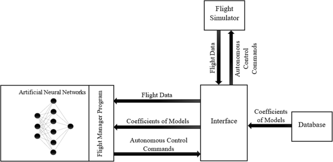
Block diagram illustrating the IAS components used during autonomous control

Here, the interface retrieves the coefficients of the models from the database for each trained ANN, and receives flight data from the flight simulator every 0.1 s. The interface organizes the coefficients into sets of weights and biases, and organizes data received from the simulator into sets of inputs for each ANN. The relevant coefficients, and flight data input sets are then fed to the Flight Manager and the ANNs of the IAS to produce outputs. The outputs of the ANNs are sent to the interface which sends them to the flight simulator as autonomous control commands using UDP packets every 0.1 s.
-
2.
The Flight Manager Program
The Flight Manager is a program which resembles a Behaviour Tree [38]. The purpose of the Flight Manager is to manage the transition between the different flight phases and their desired speed and altitude if not already selected by the user, generate and set the navigation course, and manage all the ANNs of the IAS by deciding which ANNs are to be used simultaneously at each moment. Figure 5 illustrates how the Flight Manager manages the flight phases shown in Fig. 6 by continuously examining the speed and altitude of the aircraft, and the distance to the next waypoint to detect the transition points between the different flight phases. In addition, the Flight Manager detects the Top of Descent (TOD) point where the IAS starts the descent towards the destination airport by applying (4) [39]. The Flight Manager receives the required data from the interface of the IAS as Fig. 4 shows. The methods used by the Flight Manager to manage the ANNs and the navigation course are explained in our previous work [3,4,5].

A Flowchart illustrating the process which the Flight Manager program follows to handle the transmission between the different flight phases

The different flight phases followed and managed by the Flight Manager
-
3.
Artificial Neural Networks
The relevant set of flight data inputs received through the interface is used by the ANNs’ input neurons along with the relevant coefficients to predict control commands or other data given the flight status by applying (1). The values of the output layers are sent to the interface which sends them to the flight simulator as autonomous control commands. The design approach of the ANNs intends to breakdown the different tasks required to pilot an aircraft during the multiple flight phases to small components. Following the problem breakdown approach, it is possible to achieve a composition of small multiple control units represented by the task-dedicated ANNs that can be designed, integrated, and traced effortlessly compared to systems that rely on a single or few large ANNs designed to handle multiple tasks. In addition, when following the breakdown approach, it is possible to achieve higher levels of accuracy since each ANN is dedicated towards a single task such as specific control mapping.
The design approach of the Intelligent Autopilot System breaks down the different tasks required for flying, which take place during the multiple flight phases. The break-down approach methodology identifies each control interface or surface of the aircraft, and assigns a dedicated ANN to manipulate it. For example, to control the aircraft’s pitch, the control surfaces of the aircraft that are used for this purpose are the elevators, therefore, a dedicated ANN is designed and trained to manipulate the elevators for the purpose of controlling the aircraft’s pitch. Another example is designing and training a dedicated ANN for the purpose of controlling the aircraft’s gear. The alternative for the proposed break-down approach is designing and training a single or few large ANNs that manipulate all the required interface and control surfaces of the aircraft, however, this would yield a large ANN that could represent a black-box which is difficult to design, train, and interpret. In addition, if a single control component requires redesigning or further enhancement, the single large ANN which controls all the other control components must be redesigned and retrained, which could affect the overall performance and hinder progress. Therefore, the proposed break-down approach allows for the ability to isolate any single control component for the purpose of achieving high accuracy, ease of maintenance, and introducing enhancements without affecting the overall system. Choosing the inputs and outputs of each ANN is dictated by the control problem the ANN is assigned to. For example, the ground-run phase, where the pilot attempts to gain speed required for takeoff, is done by releasing brakes (output) and pushing to full throttle (output) while monitoring airspeed (input), and the task of keeping the aircraft on the centreline of the runway is done by using the ruder (output) based on the heading (input). For these tasks, two ANNs can be designed. The first would control the brakes and throttle based on airspeed (task 1), and the second would control the rudder (task 2) based on heading, by predicting the appropriate control commands based on the relevant flight data inputs. Using Supervised Learning on these small and multiple ANNs provides the possibility to trace the complete learning and operation processes, which overcomes the black-box problem associated with some Artificial Intelligence methods such as Deep Learning that has been the main obstacle of introducing AI to the cockpit.
4 Experiments & results
Although the previous versions of the Intelligent Autopilot System (IAS) that learned from training data provided by the first author who does not have piloting experience presented cockpit autonomy capabilities [2,3,4,5], the IAS did not fully behave like an experienced human pilot of an airliner, therefore, the latest version of the Intelligent Autopilot System (IAS) was redesigned and trained with the aviation industry to achieve the desired autonomous behaviour that can be compared to the behaviour of experienced human pilots of airliners. This section discusses the experiments conducted on the latest version of the IAS.
The human teacher who provided the demonstrations is Captain Khalid Al Hashmi, a senior Oman Air pilot with more than 9000 h of flying, and the co-founder of Sahab Aviation Services which provides the necessary training for the IAS. The simulated aircraft used for the experiments is a certified Boeing B787 Dreamliner model as we want to experiment using a complex and large model with more than one engine rather than a light single-engine model. Since the design approach of the IAS which utilizes Supervised Learning and many small single-hidden-layer ANNs requires single demonstrations of the tasks to be learned, the pilot provided one demonstration of a short flight from one airport to another in X-Plane. The pilot took off from London Heathrow (EGLL), cruised at 10,000 ft., then landed in Birmingham (EGBB). The pilot followed the standard piloting procedures where he started the ground-run phase on the takeoff runway, rotated, and maintained a 15 degrees pitch angle during takeoff. Then, he engaged the aircraft’s autopilot to climb to the cruise altitude of 10,000 ft., to maintain a cruise speed of 240 knots, and to follow the preloaded flight path using GPS waypoints. Immediately after reaching the Top of Descent (TOD) point, the pilot initiated the approach flight phase by updating the speed parameter in the aircraft’s autopilot to 205 knots and starting the decent to follow the standard 3 degrees glide slope. Then, he updated the speed parameter to reach the landing speed of 150 knots before reaching the final approach flight phase. During the latter flight phases, he engaged the flaps at different altitudes to extend them to certain degrees accordingly. Finally, after the speed reached 150 knots, and at around 1500 ft., he disengaged the autopilot, and took full control of the aircraft to continue maintaining the landing speed and the 3 degrees glideslope until touchdown.
The data of interest that was collected and used to train the IAS are the inputs and outputs of the different ANNs discussed in this work and illustrated in Fig. 3. The experiments were conducted on the Elevators ANN to test the ability of maintaining the desired takeoff pitch angle, the new Elevators Trim ANNs to test the ability of maintaining different altitudes, climb rates, and the glideslope during approach and final approach, the new Throttle ANN to test the ability of maintaining different desired speeds, and the modified Flaps ANN to test the ability of extending the flaps correctly. The latter capabilities were not available in the previous versions of the IAS. Furthermore, additional experiments were conducted on the enhanced Ailerons, Rudder, and Roll ANN which replaced the Bearing Adjustment ANN from our previous work [4] to handle runway centreline maintenance during the final approach and landing flight phases in extreme weather conditions beyond the capability of the previous version of the IAS [4] and the capabilities of modern autopilots and even human pilots, as well as the Glideslope Elevators Trim ANN to test its ability to maintain the desired 3 degrees glideslope in the same extreme weather conditions. Our previous work [2,3,4,5] provide detailed explanations of the experiments of autonomous ground-run, navigation, landing procedures after touchdown, and handling emergency situations.
To assess the effectiveness of the proposed approach in this paper, the Intelligent Autopilot System (IAS) was tested in eight experiments: A. Takeoff Pitch Maintenance, B. Altitude Maintenance, C. Climb Rate Maintenance, D. Speed Maintenance, E. Flaps Setting, F. Final Approach Glideslope Maintenance, and G. Runway Centreline Maintenance. The experiments are as follows:
-
A.
Takeoff Pitch Maintenance
The purpose of this experiment is to assess the behaviour of the IAS when maintaining the 15 degrees pitch angle during the takeoff phase, and compare it to the demonstration provided by the human pilot. Since no standard modern autopilot is capable of performing autonomous takeoff, no comparison with the standard autopilot is provided.
-
1.
Training
For this experiment, the Elevators ANN and the Pitch Rate of Change ANN were trained until a low Mean Squared Error (MSE) value was achieved (below 0. 01).
-
2.
Autonomous Control
For this experiment, the aircraft was reset to the runway in the flight simulator, and the IAS was engaged to test the ability of maintaining the standard takeoff pitch angle of 15 degrees. After the IAS completed the ground-run flight phase on the runway, the output of the Elevators ANN and the Pitch Rate of Change ANN were used to hold and maintain the desired pitch angle.
-
B.
Altitude Maintenance
The purpose of this experiment is to assess the behaviour of the IAS compared to the standard autopilot of the model aircraft when maintaining a given altitude since the human pilot used the standard autopilot to handle this task.
-
1.
Training
For this experiment, the Elevators Trim ANN and the Climb Rate ANN were trained until a low Mean Squared Error (MSE) value was achieved (below 0. 01).
-
2.
Autonomous Control
After training the ANNs, the aircraft was reset to the runway in the flight simulator, and the IAS was engaged to test the ability of maintaining different altitudes selected manually by the user. After the IAS took the aircraft airborne and reached the cruise flight phase, the output of the Altitude Rate of Change ANN and the Elevators Trim ANN were used to hold and maintain three different altitudes at three different speeds, and maintain three different altitudes while speed is increasing from one speed to another and decreasing from one speed to another.
-
3
Climb Rate Maintenance
The purpose of this experiment is to assess the behaviour of the IAS compared to the standard autopilot of the model aircraft when maintaining a given climb or sink rate while changing altitude since the human pilot used the standard autopilot to handle this task.
-
1.
Training
For this experiment, the same models generated after training the Elevators Trim ANN and the Climb Rate ANN in the previous experiments (A. Altitude Maintenance) were used without having to provide additional training.
-
2.
Autonomous Control
For this experiment, the aircraft was reset to the runway in the flight simulator, and the IAS was engaged to test the ability of maintaining different climb rates selected manually by the user. After the IAS took the aircraft airborne and reached the cruise flight phase, the output of the Altitude Rate of Change ANN and the Elevators Trim ANN were used to hold and maintain six different climb or sink rates.
-
4
Speed Maintenance
The purpose of this experiment is to assess the behaviour of the IAS compared to the standard autopilot of the model aircraft when maintaining a given speed since the human pilot used the standard autopilot to handle this task.
-
1.
Training
For this experiment, the Throttle ANN and the Speed Rate of Change ANN were trained until a low Mean Squared Error (MSE) value was achieved (below 0. 01).
-
2.
Autonomous Control
After training the ANNs, the aircraft was reset to the runway in the flight simulator, and the IAS was engaged to test the ability of maintaining different speeds selected manually by the user. After the IAS took the aircraft airborne and reached the cruise flight phase, the output of the Throttle ANN and the Speed Rate of Change ANN were used to hold and maintain three different speeds at three different altitudes.
-
E.
Flaps Setting
The purpose of this experiment is to assess the behaviour of the IAS compared to the human pilot when extending and retracting the flaps given the altitude during the different flight phases.
-
1.
Training
For this experiment, the Flaps ANN was trained until a low Mean Squared Error (MSE) value was achieved (below 0. 01).
-
2.
Autonomous Control
After training the ANN, the aircraft was reset to the runway in the flight simulator, and the IAS was engaged to test the ability of correctly deploying and retracting the flaps using different settings during the ground-run phase, takeoff, approach, and final approach. The output of the Flaps ANN was used to select the different flaps settings.
-
F.
Final Approach Glideslope Maintenance
The purpose of this experiment is to assess the behaviour of the IAS compared to the standard autopilot of the model aircraft and the human pilot as well (during the last moments of final approach after disengaging the standard autopilot and taking full control) when maintaining the standard 3 degrees glideslope during the approach and the final approach flight phases in calm weather. In addition, this experiment assesses the behaviour of the IAS compared to the standard autopilot (Autoland) when maintaining the standard 3 degrees glideslope during the approach and the final approach flight phases in extreme weather conditions.
-
1.
Training
For this experiment, the Glideslope Rate of Change ANN and the Glideslope Elevators Trim ANN were trained until a low Mean Squared Error (MSE) value was achieved (below 0. 01).
-
2.
Autonomous Control
After training the ANNs, the aircraft was reset to the runway in the flight simulator, and the IAS was engaged to test the ability of maintaining the standard 3 degrees glideslope during approach and final approach in calm and extreme weather conditions. After the IAS took the aircraft airborne reached the approach flight phase, the output of the Glideslope Rate of Change ANN and the Glideslope Elevators Trim ANN were used to maintain the desired glideslope. The extreme weather conditions provided strong crosswind, gust, shear, and turbulence. The extreme weather attributes are mentioned in the next section.
-
G.
Runway Centreline Maintenance
The purpose of this experiment is to assess the behaviour of the IAS compared to the standard autopilot of the model aircraft and the human pilot as well (during the last moments of final approach after disengaging the standard autopilot and taking full control) when maintaining the centreline of the runway during the approach, final approach, and landing flight phases in calm weather. In addition, this experiment assesses the behaviour of the IAS compared to the standard autopilot (Autoland) when maintaining the centreline of the runway during the approach, final approach, and landing flight phases in extreme weather conditions. The extreme weather attributes are mentioned in the next section.
-
1.
Training
For this experiment, the Roll ANN and the Ailerons ANN were trained until a low Mean Squared Error (MSE) value was achieved (below 0. 01).
-
2.
Autonomous Control
After training the ANNs, the aircraft was reset to the runway in the flight simulator, and the IAS was engaged to test the ability of maintaining the centreline of the landing runway in calm and extreme weather conditions. After the IAS took the aircraft airborne and reached the approach flight phase, the output of the Roll ANN, the Ailerons ANN, and the Rudder ANNs were used to maintain the centreline of the landing runway. The extreme weather conditions provided strong wind including crosswind, gust, shear, and turbulence.
The following section describes the results of the conducted tests.
-
A.
Takeoff Pitch Maintenance
Two models were generated for the Elevators ANN and the Pitch Rate of Change ANN with Mean Squared Error (MSE) values of 0.004 and 0.001 consecutively. Figure 7 shows the pitch degree over time during ten different takeoffs where the IAS is controlling the elevators to maintain the standard 15 degrees pitch angle (the lines in different shades of blue) compared to the demonstration of the human pilot (the green line). Since the standard autopilot is not capable of performing takeoff autonomously, no comparison is provided. Table 2 shows the result of applying the Two One-Sided Test (TOST) [40] to examine the equivalence of the pitch degrees held by the IAS to the desired 15 degrees takeoff pitch.
-
B.
Altitude Maintenance
Fig. 7 
The pitch degrees held by the IAS over time during 15 different takeoffs (the lines in different shades of blue) compared to the demonstration of the human pilot (the green line) when maintaining a 15 degrees pitch
Table 2 Results of applying the equivalence test to examine the performance of the IAS compared to the standard autopilot when maintaining an altitude of 14,000 ft

Two models were generated for the Elevators Trim ANN and the Climb Rate ANN with MSE values of 0.01 and 0.0003 consecutively. Figures 8, 9, and 10 illustrate a comparison between the IAS and the standard autopilot when maintaining three different altitudes over time. Since the human pilot used the standard autopilot to maintain the altitude, the comparison is done between the IAS and the standard autopilot. Figure 11 illustrates a comparison between the latest version of the IAS and the previous version when holding an altitude. The previous version used the throttle to maintain a given altitude, while the latest version uses the correct flight control surface (elevators trim) to maintain a given altitude. Tables 3, 4, and 5 show the results of applying TOST to examine the equivalence between the altitude hold performance of the IAS and the standard autopilot.

A comparison between the IAS and the standard autopilot when maintaining an altitude of 14,000 ft. (speed is 250 knots)

A comparison between the IAS and the standard autopilot when maintaining an altitude of 32,000 ft. (speed is 340 knots)

A comparison between the IAS and the standard autopilot when maintaining an altitude of 4000 ft. (speed is 220 knots)

A comparison between the latest version and the previous version of the IAS when maintaining an altitude of 14,000 ft. The previous version used the throttle, while the latest version uses the elevators trim to maintain a given altitude
-
C
Climb Rate Maintenance
The same models generated for altitude maintenance (B. Altitude Maintenance) were used to maintain a given climb rate without having to retrain the models. Figures 12, 13, 14, 15, 16, and 17 illustrate a comparison between the IAS and the standard autopilot when maintaining six different climb rates over time. Since the human pilot used the standard autopilot to maintain the climb rates, the comparison is done between the IAS and the standard autopilot. No comparison with the previous version of the IAS is presented since the previous version did not have the ability to maintain climb rates. Tables 6, 7, 8, 9, 10, and 11 show the results of applying TOST to examine the equivalence between the climb rate hold performance of the IAS and the standard autopilot.

A comparison between the IAS and the standard autopilot when maintaining a climb rate of 500 ft./min (speed is 250 knots)

A comparison between the IAS and the standard autopilot when maintaining a climb rate of 1500 ft./min (speed is 280 knots)

A comparison between the IAS and the standard autopilot when maintaining a climb rate of 2500 ft./min (speed is 310 knots)

A comparison between the IAS and the standard autopilot when maintaining a climb (sink) rate of −500 ft./min (speed is 230 knots)

A comparison between the IAS and the standard autopilot when maintaining a climb (sink) rate of −1000 ft./min (speed is 240 knots)

A comparison between the IAS and the standard autopilot when maintaining a climb (sink) rate of −2000 ft./min (speed is 270 knots)
-
D
Speed Maintenance
Two models were generated for the Throttle ANN and the Speed Rate of Change ANN with MSE values of 0.0009 and 0.0006 consecutively. Figures 18, 19, and 20 illustrate a comparison between the IAS and the standard autopilot when maintaining three different speeds over time. Since the human pilot used the standard autopilot to maintain speed, the comparison is done between the IAS and the standard autopilot, however, Fig. 21 illustrates a comparison between the IAS and the human pilot when managing the different speeds throughout the complete flight from takeoff to landing. No comparison with the previous version of the IAS is presented since the previous version did not have the ability to maintain a given speed. Tables 12, 13, and 14 show the results of applying TOST to examine the equivalence between the speed hold performance of the IAS and the standard autopilot.

A comparison between the IAS and the standard autopilot when maintaining a speed of 320 knots (altitude is 22,000 ft.)

A comparison between the IAS and the standard autopilot when maintaining a speed of 350 knots (altitude is 30,000 ft.)

A comparison between the IAS and the standard autopilot when maintaining a speed of 230 knots (altitude is 10,000 ft.)

A comparison between the IAS (10 flights represented by the overlapping lines in different blue shades) and the human pilot (1 demonstration represented by the green line) when managing the different speeds over time throughout the complete flight from takeoff to landing (London Heathrow to Birmingham). As can be seen, both the IAS and the human pilot accelerated sharply until the cruise speed of 240 knots was achieved, then, decelerated gradually until the landing speed of 150 knots was achieved before coming to a full stop on the landing runway
-
E.
Flaps Setting
One model was generated for the Flaps ANN with an MSE value of 0.006. Figures 22 and 23 show the flaps setting over altitude where Fig. 22 shows the flaps setting during the ground-run, takeoff, level-up, climb, and cruise flight phases, while Fig. 23 shows the flaps setting during the cruise, approach, final approach and landing flight phases. Since the standard autopilot is not capable of controlling the flaps autonomously, the provided comparison is between the IAS and the human pilot. Table 15 shows the corresponding flaps settings given the deflection value. Table 16 shows the mean, minimum, and maximum altitudes that correlate to each flaps setting in addition to the standard deviation.

A comparison between the IAS (10 flights represented by the overlapping lines in different blue shades) and the human pilot (1 demonstration represented by the green line) when managing the different flaps settings over altitude from takeoff to cruise

A comparison between the IAS (10 flights represented by the overlapping lines in different blue shades) and the human pilot (1 demonstration represented by the green line) when managing the different flaps settings over altitude from cruise to landing
-
F.
Final Approach Glideslope Maintenance
Two models were generated for the Glideslope Rate of Change ANN and the Glideslope Elevators Trim ANN with MSE values of 0.0006 and 0.0008 consecutively. Figure 24 illustrates a comparison between the IAS, the standard autopilot, and the human pilot (the final moments of final approach after the human pilot disengaged the autopilot and took full control of the aircraft) when attempting to maintain the standard 3 degrees glideslope during final approach in calm weather. Figures 25 and 26 illustrate a comparison between the IAS and the standard autopilot (Autoland) when attempting to maintain the standard 3 degrees glideslope during final approach in extreme weather conditions with the presence of strong wind at a speed of 50 knots with gust up to 70 knots, wind shear direction of 70 degrees (around 360 degrees), and turbulence. Table 17 shows the result of applying the Two One-Sided Test (TOST) to examine the equivalence of the glideslope degrees held by the IAS, the standard autopilot, and the human pilot in calm weather. Table 18 shows the result of applying the Two One-Sided Test (TOST) to examine the equivalence of the glideslope degrees held by the IAS and the standard autopilot (Autoland) in extreme weather.

A comparison between the IAS (10 flights represented by the overlapping lines in different blue shades), the standard autopilot, and the human pilot after he took full control of the aircraft during the last moments of final approach (1 demonstration represented by the green line) when maintaining the three degrees glideslope angle from final approach to landing in calm weather

The glideslope angle of the aircraft (flown by the IAS) from final approach to landing. The goal is to try to maintain the standard 3 degrees glideslope. The weather conditions include 360 degrees wind at a speed of 50 knots with gust up to 70 knots, wind shear direction of 70 degrees, and minor turbulence

The glideslope angle of the aircraft (flown by the standard autopilot) from final approach to landing. The goal is to try to maintain the standard 3 degrees glideslope. The weather conditions include 360 degrees wind at a speed of 50 knots with gust up to 70 knots, wind shear direction of 70 degrees, and minor turbulence
-
G.
Runway Centreline Maintenance
Four models were generated for the Roll ANN, the Ailerons ANN, the Heading ANN, and the Rudder ANN with MSE values of 0.0002, 0.001, 0.003, and 0.002 consecutively. Figure 27 illustrates a comparison between the IAS, the standard autopilot of the aircraft model, and the human pilot (the final moments of final approach after the human pilot disengaged the autopilot and took full control of the aircraft) when attempting to maintain the centreline of the landing runway in calm weather. Table 19 shows the result of applying the Two One-Sided Test (TOST) to examine the equivalence of the angle between the aircraft and the landing runway held by the IAS, the standard autopilot, and the human pilot in calm weather. Figure 28 shows the angle between the aircraft’s location and the centreline of the landing runway before landing in extreme weather conditions with the presence of 90 degrees crosswind at a speed of 50 knots with gust up to 70 knots, wind shear direction of 70 degrees, and strong turbulence. In the latter weather conditions, the standard autopilot kept disengaging every time, therefore, the comparison is given between the current and the old versions of the IAS. The previous version of the IAS was able to handle severe weather conditions with wind speed up to 50 knots, and a maximum wind shear of around 22 degrees [4].

A comparison between the IAS (10 flights represented by the overlapping lines in different blue shades), the standard autopilot, and the human pilot after he took full control of the aircraft during the last moments of final approach (1 demonstration represented by the green line) when maintaining the centreline of the landing runway (0 degrees) during final approach (airborne) and landing (on the ground after touchdown) in calm weather. The angle must be between 0.05 and −0.05 degrees especially during the last moments of the final approach to ensure landing within the safe touchdown zone of the landing runway as the two dashed black lines show (right part of the chart)

A comparison between the current version of the IAS (represented by the overlapping lines in different blue shades) and the previous version of the IAS (represented by the lines in different green shades) during 10 flights each when maintaining the centreline of the landing runway (0 degrees) during final approach (airborne). The angle must be between 0.05 and −0.05 degrees especially during the last moments of the final approach to ensure landing within the safe touchdown zone of the landing runway as the two dashed black lines show (right part of the chart). The extreme weather conditions include 90 degrees crosswind at a speed of 50 knots with gust up to 70 knots, wind shear direction of 70 degrees, and strong turbulence
However, to perform a comparison between the IAS and the Autoland feature of the standard autopilot without facing the disengagement issue, the weather conditions were slightly modified by replacing the 90 degrees crosswind direction with 360 degrees, and lowering the intensity of turbulence. Figures 29 and 30 illustrate a comparison between the IAS and the standard autopilot when attempting to intercept the centreline of the landing runway (airborne) in the slightly modified weather conditions. Table 20 shows the number of successful and unsuccessful attempts to keep the aircraft within the safe zone (angle between 0.05 and −0.05 degrees) during final approach while airborne. Figures 31 and 32 illustrate a comparison between the IAS and the standard autopilot when attempting to intercept the centreline of the landing runway after touchdown in extreme weather conditions with the presence of strong wind at a speed of 50 knots with gust up to 70 knots, wind shear direction of 70 degrees (around 0 degrees), turbulence, and high precipitation (wet runway). Table 21 shows the number of successful and unsuccessful attempts to keep the aircraft within the safe zone of the runway (angle between 0.05 and −0.05 degrees) after touchdown while attempting to decrease the speed to taxi speed.

The angle between the aircraft (flown by the IAS) and the centreline of the runway (0) during ten different final approach attempts (airborne). The angle must be between 0.05 and −0.05 degrees especially during the last moments of the final approach to ensure landing within the safe touchdown zone of the landing runway as the two dashed black lines show (right part of the chart). The weather conditions include 360 degrees wind at a speed of 50 knots with gust up to 70 knots, wind shear direction of 70 degrees, and minor turbulence

The angle between the aircraft (flown by the standard autopilot) and the centreline of the runway (0) during ten different final approach attempts (airborne). The angle must be between 0.05 and −0.05 degrees especially during the last moments of the final approach to ensure landing within the safe touchdown zone of the landing runway as the two dashed black lines show (right part of the chart). The weather conditions include 360 degrees wind at a speed of 50 knots with gust up to 70 knots, wind shear direction of 70 degrees, and minor turbulence

The angle between the aircraft (flown by the IAS) and the centreline of the runway (0 degrees) during ten different landing attempts. The angle must be between 0.05 and −0.05 degrees during touchdown to ensure landing within the safe touchdown zone of the landing runway as the two dashed black lines show (right part of the chart), and during the attempt to decrease the aircraft’s speed on the runway to taxi speed. The weather conditions include 360 degrees wind at a speed of 50 knots with gust up to 70 knots, wind shear direction of 70 degrees, and minor turbulence

The angle between the aircraft (flown by the standard autopilot) and the centreline of the runway (0 degrees) during ten different landing attempts. The angle must be between 0.05 and −0.05 degrees during touchdown to ensure landing within the safe touchdown zone of the landing runway as the two dashed black lines show (right part of the chart), and during the attempt to decrease the aircraft’s speed to taxi speed. The weather conditions include 360 degrees wind at a speed of 50 knots with gust up to 70 knots, wind shear direction of 70 degrees, and minor turbulence
As can be seen in Fig. 7 (A. Takeoff Pitch Maintenance), the IAS was able to maintain the standard pitch angle of 15 degrees during the takeoff phase. Table 2 shows that the IAS was able to maintain a pitch angle mean of 15.24 degrees which is equivalent to the 15.17 degrees mean maintained by the human pilot as the equivalence test shows.
Figures 8, 9, and 10 (B. Altitude Maintenance) show that the IAS was able to maintain three different altitudes at three different speeds as did the standard autopilot. Tables 3, 4, and 5 show that the performance of the IAS when maintaining a given altitude at a given speed is equivalent to the performance of the standard autopilot. Figure 11 shows the significant improvement in the ability of maintaining a given altitude by comparing the previous version of the IAS which was not able to accurately maintain altitudes with the current version which now have the ability to handle this task precisely. However, Figs. 8, 9 and 10 show that the performance of the IAS showed oscillations.
Figures 12, 13, 14, 15, 16, and 17 (C. Climb Rate Maintenance), and Tables 6, 7, 8, 9, 10, and 11 show that although the performance of the IAS showed oscillations when maintaining climb rates, it performed better than the standard autopilot when maintaining six different climb/sink rates at six different speeds. Figures 18, 19, and 20 illustrate the equivalent performances of the IAS and the standard autopilot when maintaining three different speeds at three different altitudes. Tables 12, 13, and 14 confirm the equivalence between the performances of the IAS and the standard autopilot when handling this task. Figure 21 shows that the IAS was able to manage and maintain the different speeds in the different flight phases from takeoff to landing in a manner that is identical to the human pilot throughout the same flight.
It is clear that the oscillations are recurrent in both experiments (B. Altitude Maintenance and C. Climb Rate Maintenance), and they can only be seen when controlling the elevators trim control surfaces using the Elevators Trim ANN. This ANN was trained to handle two different tasks which are maintaining climb/sink rates and maintaining altitudes. The reason for having just one ANN for both tasks is because these tasks are handled using the same control surfaces of the aircraft (the elevators trim). However, it is clear that following the general approach in this work of designing and training dedicated ANNs that handle specific tasks showed excellent results in all the previous chapters and most of the work in this chapter, therefore, based on the results of using dedicated ANNs for specific tasks, it is likely that segregating the tasks could improve or eliminate the oscillations, which can be explored in future work.
Figures 22 and 23 (E. Flaps Setting) illustrate the consistent behaviour of the IAS when extending and retracting the flaps given the flight phase and altitude, which is identical to the behaviour of the human pilot when handling this task. The minor differences shown in Table 16 are due to the terrain variation below the aircraft since the applied altitude here is feet above ground level instead of sea level
Figure 24 (F. Final Approach Glideslope Maintenance) shows the identical performance of the IAS, the standard autopilot, and the human pilot when maintaining the standard 3 degrees glideslope angle during final approach and landing in calm weather. Table 17 confirms the equivalence between the performance of the IAS, the standard autopilot, and the human pilot when handling this task. Figures 25 and 26 show the similar performance of the IAS and the standard autopilot (Autoland) while maintaining the standard 3 degrees glideslope angle in extreme weather conditions including 360 degrees wind at a speed of 50 knots with gust up to 70 knots, wind shear direction of 70 degrees, and minor turbulence. Table 18 shows that the means of the glideslope angle maintained by the IAS and the standard autopilot are equivalent, however, the IAS performed better since the glideslope mean is 3.01 which is significantly closer to the desired 3 degrees glideslope compared to the 2.93 mean achieved by the standard autopilot
As can be seen in Fig. 27 (G. Runway Centreline Maintenance), the IAS was able to maintain the centreline of the landing runway as did the human pilot and the standard autopilot in calm weather. Table 19 confirms the equivalence between the performance of the IAS, the human pilot, and the standard autopilot when handling this task. Figures 28 and 29 show that the IAS was able to keep the aircraft within the safe zone (between 0.05 and −0.05 degrees from the centreline of the runway) in extreme weather conditions including 90 degrees crosswind at a speed of 50 knots with gust up to 70 knots, wind shear direction of 70 degrees, and strong turbulence, while the standard autopilot kept disengaging every time in the latter weather conditions. Compared to the previous version of the IAS which achieved a success rate of 40% (4 successful attempts out of 10 trials), the current version achieved a success rate of 100% (10 successful attempts out of 10 trials) as Table 20 and Fig. 28 show when intercepting the centreline of the landing runway in such extreme weather conditions. After altering the weather conditions by replacing the 90 degrees crosswind with 360 degrees wind and lowering the intensity of turbulence, the standard autopilot was able to land, however, as Fig. 30 shows, the standard autopilot struggled to keep the aircraft within the safe zone (between 0.05 and −0.05 degrees from the centreline of the runway). Table 21 shows that the IAS was able to achieve a success rate of 100% (20 successful attempts out of 20 trials), while the standard autopilot achieved a success rate of 25% (5 successful attempts out of 20 trials) which confirms that the IAS can perform significantly beyond the capabilities of modern standard autopilots in extreme weather conditions. In addition, Fig. 31 illustrates the excellent performance of the IAS while trying to keep the aircraft within the safe zone of the landing runway (between 0.05 and −0.05 degrees from the centreline of the runway) after touchdown while decreasing the speed of the aircraft on the runway to taxi speed, while Fig. 32 illustrates the poor performance of the standard autopilot when attempting to handle the same task in the same extreme weather conditions. In addition, Table 21 shows that the IAS was able to achieve a success rate of 100% (10 successful attempts out of 10 trials), while the standard autopilot achieved a success rate of 20% (2 successful attempts out of 10 trials) while maintaining the centreline of the landing runway after landing, which further confirms the superior performance of the IAS which is beyond the capabilities of standard autopilots.
Overall, the distinct performance of the IAS, which shows a natural and dynamic behaviour when handling the different tasks by manipulating the different control surfaces especially in extreme weather conditions proved its superiority compared to the mechanical-precision-like performance of the standard autopilot, which according to the literature, suffers from robustness issues when facing uncertainty, which hinders the reaction time, and the ability to cope with such extreme and sometimes sudden conditions. Figure 33 shows the moment of touchdown on the landing runway in the presence of extreme crosswind conditions where the wind speed is 64 knots, and the wind direction is around 270 degrees as the weather values show on the IAS interface (near bottom left corner).Footnote 1

The moment of touchdown on the landing runway by the IAS in the presence of extreme crosswind conditions beyond the current limits and capabilities
5 Evaluating the IAS by the aviation industry
To involve the aviation industry in evaluating the performance of the IAS, and in addition to providing training data for the IAS, the experienced pilot provided his feedback after being presented with complete (airport to airport) flight demonstrations of the IAS, and landings in calm and extreme weather conditions as the experiments above show. We asked him the following questions, and he answered as follows:
-
1.
Compared to the standard modern autopilot, what is your impression of the performance of the IAS when executing complete flights in calm and severe weather conditions? “Good. I Wish we can try the IAS in a 6-axis full motion flight simulator to evaluate it further.”
-
2.
Although flying in such conditions is probably against regulations, but for testing purposes, is the IAS capable of preforming crosswind landings beyond the current limits and capabilities of modern autopilots? What about experienced human pilots? “Yes. It is always a challenge, human pilots are allowed to land in crosswind conditions up to the demonstrated limit such as 38 knots, whereas the autopilots limit is less. I Hope that the IAS can help in increasing the crosswind limit which is sometimes limited due to flight controllability rather than pure capability.”
-
3.
Is the current performance of the IAS in general comparable with human pilots? If yes, as an experienced captain and instructor, how would you rate its performance if it were human? novice, intermediate, or experienced? “Yes, I would say intermediate although I suggest comparing it more with other autopilot.”
-
4.
Do you agree that the IAS has the potential to introduce new advantages to the aviation industry such as enhancing safety as a dependable autopilot compared to the modern ones? “Yes, it does. It just needs to be trained more on scenarios and various conditions and malfunctions.”
6 Conclusion
In this work, a novel and robust approach is proposed, which provides an intelligent control methodology that tackles the robustness issues of modern autopilots of airliners such as handling severe weather conditions throughout the flight especially during crosswind landing. The main contributions of this work are:
-
1.
Proving the ability of Artificial Neural Networks and the learning from demonstration concept to learn piloting tasks by generating learning models from training datasets containing demonstrations performed by a human teacher in a flight simulator. The learning models capture low-level and high-level skills and abilities that enabled the IAS to perform basic flights under calm and severe weather conditions.
-
2.
Teaching ANNs complex flying tasks including the ability to takeoff from airport A, navigate to airport B, and land safely.
-
3.
Proving the ability of Artificial Neural Networks and the learning from demonstration concept to not only learn how to fly an aircraft, but to learn how to fly and execute the necessary piloting tasks like experienced human pilots of airliners, and to handle landings in extreme weather conditions that are beyond the current limits and abilities of modern autopilots and experienced human teachers as well.
The proposed approach “teaches” the Intelligent Autopilot System (IAS) how to perform the necessary set of piloting tasks while flying from one airport to another in a manner that is comparable to experienced human pilots of airliners, and beyond. Compared to the previous versions of the IAS, the newly designed and trained ANNs can now handle tasks including maintaining the desired pitch angle during takeoff, maintaining different altitudes, climb/sink rates, speeds, and controlling the flaps by manipulating the appropriate control surfaces. This approach introduces the possibility to have an autopilot that behaves like a skilled human pilot rather than a machine with limited capabilities. In addition, the newly acquired abilities include performing landings in extreme weather conditions with extreme crosswind, gust, shear, and turbulence beyond the current limits and abilities, which increases safety significantly. Exploiting Supervised Learning, and applying Artificial Neural Networks proved to be an effective approach to train the IAS how to handle such conditions as parts of the overall ability of the IAS to perform complete flights from takeoff to landing autonomously with minimum effort. The experiments were strong indicators towards the ability of Supervised Learning with Artificial Neural Networks to capture low-level piloting tasks such as the rapid manipulation of the elevators and the elevators trim to maintain the required takeoff pitch angle, different altitudes, different climb/sink rates, and the rapid manipulation of the ailerons, rudder, and the elevators trim to intercept the centreline of the landing runway, and to maintain the required three degrees glideslope during final approach. Furthermore, the experiments were strong indicators towards the ability of the proposed approach to capture high-level tasks as well such as extracting and retracting the flaps according to the flight phase and altitude.
Breaking down the piloting tasks and adding more Artificial Neural Networks allows the system to overcome the black-box problem by having multiple small ANNs with single-hidden-layers that learn from small labelled datasets which have clear patterns. In addition, this approach enhanced performance and accuracy, and allowed the coverage of a wider spectrum of tasks.
The aviation industry is currently working on solutions which would lead to decreasing the dependence on human pilots. The reason behind this is to lower the workload, human error, stress, and handle the pilots’ shortage problem compared to the high demand for new airplanes, by developing autopilots capable of performing complete flights without human intervention. We anticipate that future autopilot systems which make of methods proposed here could improve safety and handle the challenges faced by the industry.
Notes
For more videos showing the capabilities of the IAS in calm and extreme weather conditions: http://www0.cs.ucl.ac.uk/staff/H.Baomar/
References
R. Khan-Persaud (2013) ECCAIRS aviation 1.3.0.12 (VL for ATTrID 391 – event phases). ICAO Safety, [online]. The International Civil Aviation Organization (ICAO). Available: https://www.icao.int/safety/airnavigation/AIG/Documents
H. Baomar and P. J. Bentley (2016) An intelligent autopilot system that learns piloting skills from human pilots by imitation. 2016 international conference on unmanned aircraft systems (ICUAS). Arlington, VA, USA, pp. 1023–1031
H. Baomar and P. J. Bentley (2016) An Intelligent Autopilot System that learns piloting skills from human pilots by imitation, 2016 International Conference on Unmanned Aircraft Systems (ICUAS), Arlington, VA, 2016, pp. 1023–1031. https://doi.org/10.1109/ICUAS.2016.7502578.
H. Baomar and P. J. Bentley (2017) Autonomous landing and go-around of airliners under severe weather conditions using Artificial Neural Networks, 2017 Workshop on Research, Education and Development of Unmanned Aerial Systems (RED-UAS), Linköping, Sweden, 2017, pp. 162–167. https://doi.org/10.1109/RED-UAS.2017.8101661.
H. Baomar and P. J. Bentley (2017) Autonomous navigation and landing of large jets using artificial neural networks and learning by imitation. 2017 IEEE symposium series on computational intelligence (SSCI). Honolulu, HI, pp. 1–10
D. We, H. Xiong and J. Fu (2015) Aircraft autopilot pitch control based on fuzzy active disturbance rejection control. 2015 international conference on industrial informatics – computing technology, intelligent technology, industrial information integration. Wuhan, pp. 144–147
Beygi, Nima, Beigy, Maani and Siahi, Mehdi. (2015) Design Of Fuzzy Self-Tuning PID Controller For Pitch Control System Of Aircraft Autopilot. [online]. Available at: arXiv.org. Accessed 11 Apr 2017.
H. L. Jeevan, H. K. Narahari and A. T. Sriram (2018) Development of pitch control subsystem of autopilot for a fixed wing unmanned aerial vehicle. 2018 2nd international conference on inventive systems and control (ICISC). Coimbatore, pp. 1233–1238
Motea Z, Wahid H, Zahid J, Lwin S, Hassan A (2018) A comparative analysis of intelligent and PID controllers for an aircraft pitch control system. Appl Model Simul (AMS) 2(1):17–25
J. Qiu, I. S. Delshad, Q. Zhu, M. Nibouche and Y. Yao (2017) A U-model based controller design for non-minimum phase systems: application to Boeing 747 altitude-hold autopilot. 2017 9th international conference on modelling, identification and control (ICMIC). Kunming, pp. 122–127
Muliadi J, Kusumoputro B (2018) Neural network control system of UAV altitude dynamics and its comparison with the PID control system. J Adv Transp 2018:1–18
N. C. Mumm and F. Holzapfel (2017) Vertical speed command performance improvement of a load factor command based autopilot for automatic landing by shaping the desired command during flare. 2017 IEEE conference on control technology and applications (CCTA). Mauna Lani, HI, pp. 1117–1122
Stukenborg P, Luckner R (2018) Evaluating the influence of continuous flap settings on the take-off performance of an airliner using flight simulation. CEAS Aeronaut J 9(4):671–681
Dong J, Zhou D, Shao C, Wu S (2018) Nonlinear system controllability analysis and autopilot design for bank-to-turn aircraft with two flaps. Proc Inst Mech Eng Part G: J Aerosp Eng 233(5):1772–1783
Oszust M, Kapuscinski T, Warchol D, Wysocki M, Rogalski T, Pieniazek J, Kopecki G, Ciecinski P, Rzucidlo P (2018) A vision-based method for supporting autonomous aircraft landing. Aircr Eng Aerosp Technol 90(6):973–982
Theis J, Ossmann D, Thielecke F, Pfifer H (2018) Robust autopilot design for landing a large civil aircraft in crosswind. Control Eng Pract 76:54–64
de Bruin A, Jones T (2016) Accurate autonomous landing of a fixed-wing unmanned aircraft under crosswind conditions. IFAC-PapersOnLine 49(17):170–175
Zhang L, Zhai Z, He L, Niu W (2019) Infrared-based autonomous navigation for civil aircraft precision approach and landing. IEEE Access 7:28684–28695
Bian Q, Nener B, Wang X (2018) Control parameter tuning for aircraft crosswind landing via multi-solution particle swarm optimization. Eng Optim 50(11):1914–1925
Viswanathan R, Lakshmi P (2017) A novel method for controlling the roll angle of aircraft using sliding mode control methodology. J Inst Eng (India): Ser C 99(4):369–372
S. U. Ali, R. Samar and M. Z. Shah (2017) UAV lateral path following: nonlinear sliding manifold for limited actuation. 2017 36th Chinese control conference (CCC). Dalian, pp. 1348–1353
Nikolai Botkin, Varvara Turova (2015) Aircraft runway acceleration in the presence of severe wind gusts. 27th IFIP conference on system modeling and optimization (CSMO). Sophia Antipolis, France, pp. 147–158
Lungu R, Lungu M (2017) Automatic landing system using neural networks and radio-technical subsystems. Chin J Aeronaut 30(1):399–411
Evdokimenkov V., Kim R., Krasilshchikov M., Sebrjakov G. (2016) Individually adapted neural network for pilot’s final approach actions modeling. In: Cheng L., Liu Q., Ronzhin A. (eds) Advances in neural networks – ISNN 2016. ISNN 2016
A. Altun and M. Önder Efe (2019) Aircraft control with neural networks. 2019 6th international conference on control, decision and information technologies (CoDIT). Paris, France, pp. 429–433
Y.S Mandloi, Y. Inada (2019) Machine Learning Approach for Drone Perception and Control. https://doi.org/10.1007/978-3-030-20257-6_36.
Bai W, Zhou Q, Li T, Li H (2020) Adaptive reinforcement learning neural network control for uncertain nonlinear system with input saturation. IEEE Trans Cybern 50(8):3433–3443
D. Shukla, S. Keshmiri and N. Beckage (2020) Imitation learning for neural network autopilot in fixed-wing unmanned aerial systems. 2020 international conference on unmanned aircraft systems (ICUAS). Athens, Greece, pp. 1508–1517
A. Elbatal, M. M. Elkhatib and A. M. Youssef (2020) Intelligent autopilot design based on adaptive neuro -fuzzy technique and genetic algorithm. 2020 12th international conference on electrical engineering (ICEENG). Cairo, Egypt, pp. 377–382
X. Zhai, K. Liu, W.Nash, & D. Castineira, (2020, January 13) Smart autopilot drone system for surface surveillance and anomaly detection via customizable deep neural network. International Petroleum Technology Conference
E. Alvis, D. Bhatt, B. Hall, K. Driscoll, A. Murugesan Aerospace Advanced Technology Labs, Honeywell International, Inc (2018) Final technical report for NASA project. Assurance reasoning for increasingly autonomous systems (ARIAS). [online] Available at: https://ntrs.nasa.gov/archive/nasa/casi.ntrs.nasa.gov/20180006312.pdf
Abbeel, P., & Ng, A. Y. (2004) Apprenticeship learning via inverse reinforcement learning. In: Proc of the twenty-first international conference on machine learning (p. 1)
F. Wei, A. Bower, L. Gates, A. Rose, and D. T. Vasko (2016) The full-scale helicopter flight simulator design and fabrication at CCSU. 57th AIAA/ASCE/AHS/ASC structures, structural dynamics, and materials conference
M. Jirgl, J. Boril, and R. Jalovecky (2015) The identification possibilities of the measured parameters of an aircraft model and pilot behavior model on the flight simulator, pp. 1–5. https://doi.org/10.1109/MILTECHS.2015.7153726.
Kaviyarasu A, Kumar S (2014) Simulation of flapping-wing unmanned aerial vehicle using X-plane and Matlab/Simulink. Def Sci J 64(4):327–331
J. McCaffrey (2014) Understanding neural networks using .NET, [Presentation]. The microsoft 2014 build conference. San Francisco, USA
Heaton J (2015) Artificial intelligence for humans, volume 3: deep learning and neural networks. Heaton Research, Inc., St. Louis
K. Winter, I. J. Hayes, and R. Colvin (2010) Integrating requirements: the behavior tree philosophy. 2010 8th IEEE international conference on software engineering and formal methods, Pisa, pp. 41–50
E. L’hotellier and J. Salzmann (2017) Top of descent calculation. [online] the international virtual aviation organisation, IVAO. Available at: https://www.ivao.aero/training/documentation/books/SPP_APC_Top_of_descent.pdf
Schuirmann DJ (1987) A comparison of the two one-sided tests procedure and the power approach for assessing the equivalence of average bioavailability. J Pharmacokinet Biopharm 15(6):657–680
Acknowledgements
We wish to acknowledge Captain Khalid Al Hashmi and Sahab Aviation Services for providing us with their valuable time, facilities, and support which allowed for the collection of the necessary training data to train the Intelligent Autopilot System (IAS) as well as evaluating it. This collaboration contributed to the preparation of this research paper.
Author information
Authors and Affiliations
Corresponding author
Additional information
Publisher’s note
Springer Nature remains neutral with regard to jurisdictional claims in published maps and institutional affiliations.
Rights and permissions
Open Access This article is licensed under a Creative Commons Attribution 4.0 International License, which permits use, sharing, adaptation, distribution and reproduction in any medium or format, as long as you give appropriate credit to the original author(s) and the source, provide a link to the Creative Commons licence, and indicate if changes were made. The images or other third party material in this article are included in the article's Creative Commons licence, unless indicated otherwise in a credit line to the material. If material is not included in the article's Creative Commons licence and your intended use is not permitted by statutory regulation or exceeds the permitted use, you will need to obtain permission directly from the copyright holder. To view a copy of this licence, visit http://creativecommons.org/licenses/by/4.0/.
About this article

Cite this article
Baomar, H., Bentley, P.J. Autonomous flight cycles and extreme landings of airliners beyond the current limits and capabilities using artificial neural networks. Appl Intell 51, 6349–6375 (2021). https://doi.org/10.1007/s10489-021-02202-y
Accepted:
Published:
Issue Date:
DOI: https://doi.org/10.1007/s10489-021-02202-y