
Abstract
Muography is a novel imaging method using natural cosmic-ray radiation for characterising and monitoring variation in average material density in a diverse range of objects that cannot be imaged by conventional imaging techniques. Muography includes muon radiography and muon tomography. Cosmic-ray-induced muons were discovered in the 1930’s, but rapid development of both muographic techniques has only occurred in the last two decades. With this rapid development, muography has been applied or tested in many fields such as volcano imaging, archaeology, underground structure and tunnel detection, rock mass density measurements, cargo scanning, imaging of nuclear waste and reactors, and monitoring of historical buildings and the inside of blast furnaces. Although applications of muography have already touched mining and rock engineering, such applications are still rare and they are just beginning to enter the market. Based on this background, this paper aims to introduce muography into the fields of mining and rock engineering. First, the basic properties of muons are summarized briefly. Second, potential applications of muography to mining and rock engineering are described. These applications include (1) monitoring temporal changes in the average material density of fracturing and deforming rock mass; (2) detecting geological structures and isolated ore bodies or weak zones in mines; (3) detecting a reservoir or boulders during tunnelling or drifting; (4) monitoring caving bodies to search remaining ore; (5) evaluating and classifying rock masses; (6) exploring new mineral deposits in operating underground mines and their surrounding brownfields. Finally, some issues such as maximum depth muons can reach are discussed.
1 Introduction
For a long time, it has been a great dream for scientists and engineers in mining and rock engineering to “see” the inside of a rock mass since the rock mass is a complex and opaque natural solid that cannot be deeply penetrated by common techniques such as X-rays. One operationally feasible method to collect information from the inside of rock mass is to use core-drilling to take out cores from the rock mass. However, to know the inside of rock mass very well, the drilling cost will be extremely high since a great number of drill holes will be needed in a specific rock project. Therefore, the drilling method is very limited and it cannot be used widely and sufficiently. In addition to the drilling method, there are many conventional geophysical methods available for characterisation of rock masses, such as seismic imaging, electromagnetic, magnetic, ground-penetrating radar and gravity methods (Takahashi 2004; Takahashi et al. 2006). Each of these methods has its shortcomings in terms of usefulness or usability in mining and rock engineering applications (e.g., inadequate coverage, lack of required resolution for the task, high logistical costs, difficulties in availability, and need for specifically trained or even outsourced professional personnel). In summary, as the information of inside rock mass is often lacking, mining engineering and other types of rock engineering often face various challenges and problems in natural resources recovery, mining production, tunnelling, underground construction, productivity, cost of rock support, safety, and impact on the environment.
Some shortcomings of the traditional methods mentioned above can be overcome by a relatively new remote mapping method called muography. This method is conceptually similar to X-ray imaging and hence is sensitive to density. However, unlike X-ray based methods, muography does not require the transmission of any form of artificial radiation or radioactive sources. Instead, it relies on natural muon flux that originates from the Earth’s atmosphere. The benefits of applying muography in mining and rock engineering are inherently both technical and economic. With muography one can investigate density contrasts in much larger rock volumes than using expensive and time-consuming drilling, and create notable savings in money (e.g., less unnecessary drilling), time (e.g., less drilling) and human resources (e.g., less drill logging). Using the density contrasts, one may find an undiscovered small ore body in an operating mine, the location of remained ore left in an underground mine, and a structurally weak zone or a fractured volume of the rock mass. In addition, muography has other potential applications such as evaluating rock mass in mining and rock engineering.
Muons are sub-atomic particles created in the upper layers of the atmosphere. Muons are secondary products of cosmic-rays and they are extremely penetrating particles. Only the most energetic muons can travel from the ground surface down to more than 2000 m deep until stopped or decaying to other particles (Jillings 2016; Wu et al. 2013). Muons were discovered in 1936 by Neddermeyer and Anderson (1937). The earliest tests on how muons could be used in sciences were conducted by George (1955) and Alvarez et al. (1970). The former measured the rock overburden of a hydroelectric plant tunnel in Australia, while the latter surveyed a pyramid in Egypt. The imaging method based on muon detection is nowadays referred to as muography (for example, see Tanaka et al. 2009).
Up till now muography has been applied to or tested in many fields. For example, muography has been used in the imaging of volcanoes (Nagamine et al. 1995; Tanaka et al. 2007, 2009, 2014; Okubo and Tanaka 2012; Lesparre et al. 2012; Marteau et al. 2012, 2015; Shinohara and Tanaka 2012; Carlôganu et al. 2013; Tanaka and Yokoyama 2013; Nishiyama et al. 2014; Ambrosino et al. 2015b; Jourde et al. 2016; Tioukov et al. 2017; Noli et al. 2017; Kaiser 2019; D’Alessandro et al. 2019; Oláh et al. 2019; Tanaka 2019; Barnoud et al. 2019; Lelièvre et al. 2019), in mining exploration (Schouten 2019), in the imaging of underground structures (Bonneville et al. 2019; Saracino et al. 2019), in archaeology and tunnel detection (Basset et al. 2006; Menichelli et al. 2007; Levy et al. 1988; Celmins 1990; Caffau et al.1997; Morishima et al. 2017), in the monitoring of carbon capture storage sites (Kudryavtsev et al. 2012; Jiang et al. 2013; Klinger et al. 2015; Gluyas et al. 2019), in scanning old mining sites to detect the possible presence of unknown cavities (Baccani et al. 2019; Mitrica et al. 2019), in investigation of mineral deposits and rock density measurements (Malmqvist et al. 1979; Guardincerri et al. 2017; Bryman et al. 2014; Kaiser 2019), in cargo scanning and imaging of nuclear waste and reactors (Gnanvo et al. 2010; Lo Presti et al. 2012; Jonkmans et al. 2013; Miyadera et al. 2013; Perry et al. 2013; Clarkson et al. 2014; Morris et al. 2014; Ambrosino et al. 2015a; Thomay et al. 2016; Dobrowolska et al. 2018; He et al. 2018; Riggi et al. 2018; Frazão et al. 2019; Mahon et al. 2019), and in civil engineering such as the monitoring of historical buildings and the inside of blast furnaces (Zenoni et al. 2014; Guardincerri et al. 2016; Saracino et al. 2019; Vanini et al. 2019). In principle, all large structures such as bridges, wind turbines, dams, etc., can be monitored using muon radiography. Muon fluxes have been measured in all deep underground laboratories of astroparticle physics. For example, in the Pyhäsalmi mine, Finland (Enqvist et al. 2005), approximately 1200 muons/m2 were detected at the depth of 1390 m below the ground in about 100 days; in the Canfranc Underground Laboratory, Spain (Trzaska et al. 2019) the shapes of the mountain overburden were scanned; in JinPing Underground Laboratory, China (Wu et al. 2013) and in Vale Creighton Mine, Canada (Jillings 2016) muons were monitored at depths of 2400 m and 2000 m below the ground surfaces, respectively.
The rapidly growing applications of muography in the fields mentioned above have opened a door for mining and rock engineering in which muography has a large potential to play a great positive role. Although muography has been tried in or applied to many fields mentioned above, its applications to mining engineering and rock engineering are still scarce. Therefore, it is necessary to introduce muography to mining and rock engineering so that this relatively new technology can be applied to solve problems in these fields. Accordingly, this paper will briefly introduce the basic properties and characteristics of muons before describing the potential applications of muography to mining and rock engineering.
2 Muons and Muography
2.1 Characteristics of Muons
Properties and characteristics of muons can be found in many publications (e.g., Tanaka 2013; Holma et al. 2019; Kaiser 2019; Yang et al. 2019) and their main physical properties and other characteristics can be summarized, as follows:
-
(1)
Muons Are Natural, Abundant and Free to Use
Muons are generated within a rather broad distribution of 10–20 km in the atmosphere resulting from interactions between atmospheric nuclei and high-energy cosmic particles (cosmic rays), as illustrated in Fig. 1. The production of the cosmic-ray-induced muon is a random process. Therefore, the muon trajectory and its production position are randomly distributed. This process is continuous and offers a never-ending reservoir of muons which impact on and, as they are very penetrative particles, beneath the ground.
Fig. 1 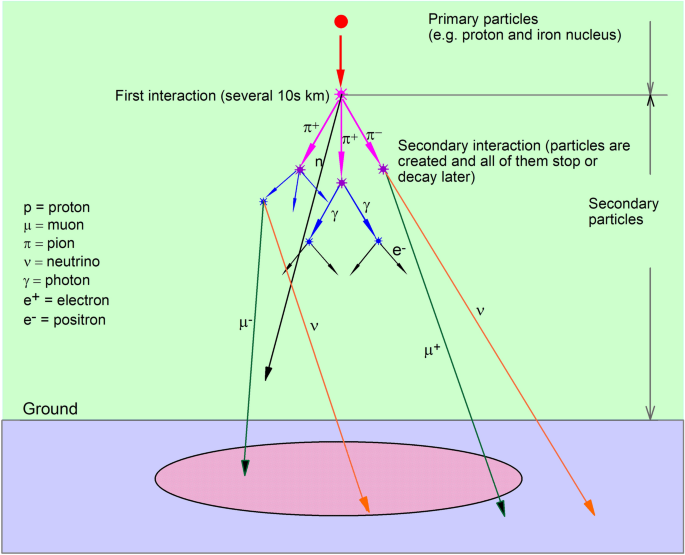
Diagram of primary and secondary particles. Secondary particles are produced by the interaction of primary particles with the atmospheric nuclei in tens of kilometres above the surface of the earth. The secondary particles include many particles such as muon, pion, neutrino, photon, electron, etc. Among these secondary particles, only muon and neutrino can penetrate deep into the ground. However, detection of neutrinos requires large instruments because of their very weak interaction with any matter and presently it is not practical to detect neutrinos for geological or mining engineering purposes. Note that the angles of produced particles are exaggerated for clarity and, for example, the produced muons are parallel within approximately 1°
-
(2)
Muons Have High Energy, Heavy Mass and Constant Flux
Muons are produced in the Earth’s atmosphere with known angular (i.e., direction) and energy distributions with an average energy of 3 GeV, approximately 10,000 times the energy of a typical X-ray, and with the practically constant flux of the order of 150–200 muons/m2 per second at sea level, or 1 muon/(cm2 min) (Beringer et al. 2012; Schouten 2019). In addition, compared with other similar particles muons are notably heavy. Muons have a mass of 105.66 MeV/c2, which is approximately 207 times that of the electron (Yang et al. 2019).
The high energy and heavy mass lead to straight and longer tracks in the Earth’s magnetic field and in rock, and their scattering and other such effects have a negligible impact on their track, no matter in which matter the muons travel, as illustrated in Fig. 2. However, multiple scattering cannot be neglected for muons that have only little energy at the time of detection. Regarding rock and mining engineering applications, such muons are more common on surface (e.g., open pit mines) applications of muography due to an excess of low-energy muons on the ground level.
Fig. 2 
Diagram of muon travel and detector. A detector can monitor a large area shown by angle α. The maximum α may be up to 90°
While the muon flux is constant day and night this rather low flux is not a challenge for any data acquisition system, but sufficient to take some useful data. This together with their good penetrability means that muons are well suited to image objects that are behind or inside of shielding material that is too thick to be imaged by any other imaging methods.
Notice that although the muon flux is almost constant, many factors such as atmospheric pressure and/or solar activity can affect the muon flux rate. These factors should be taken into account in corresponding applications of muon imaging.
-
(3)
Muons Are Highly Penetrating, Absorbable and Detectable
Muons suffer less energy losses than any other particles (except for neutrinos) while passing through matter (e.g., Tanabashi et al. 2018) mainly due to their heavy mass and high energy. Therefore, they can penetrate into a very deep rock mass. For example, at depths of 1390 m, 2000 m and 2400 m below the ground surface muons were detected in Finland (Enqvist et al. 2005), Canada (Jillings 2016) and China (Wu et al. 2013), respectively, indicating that muons can penetrate into hard rock mass with at least a thickness of 2400 m. In addition, the measurements clearly show that the muon flux density (counts/m2s) decreases rapidly with increasing depth.
Moreover, the measurements demonstrate that muons are absorbed during their travel. The muon absorption rate is utterly independent on the chemical composition of the rock (Tanaka 2013). Hence, the attenuation of cosmic-ray muons passing through any matter can be used to estimate the density of the matter. The denser the matter, the more muons it absorbs before they ever reach the muon detector. Therefore, the attenuation of muons in various directions can be associated with the density variations in the media.
As electrically charged and fast-moving particles, muons are relatively easy to detect with several different types of detectors. For example, plastic scintillator detectors with a 1–5 cm thick plastic are generally used to detect muons.
-
(4)
Muons Are Safe to Use
It has not been found that muons expose any health risks (in contrast to, e.g., X-rays) and they harm environment in any notable way up till now. Therefore, their usage is not governed by safety regulations.
-
(5)
Muons Have a Lifetime of 2.2 µs
The 2.2 µs lifetime of muons is much longer than many other subatomic particles. Furthermore, cosmic-ray-induced muons are relativistic particles and their relativistic speed results in time dilatation (according to Einstein’s theory of relativity). Therefore, fast-moving muons live in much longer than their counterparts at rest, allowing them to travel very deep underground.
-
(6)
Utilization of Muons Requires No Radiological Sources
As muons are a component of natural radiation background their utilization requires no radiological sources.


2.2 Muography and Muon Detectors
This section introduces the concept of muography and different types of muon detectors, while the principles of muography are introduced in the next section.
-
(1)
Muography
Muography is an umbrella term combining two different overlapping muon-based imaging techniques within its scope, namely muon radiography (2D muon imaging) and muon tomography (3D muon imaging). Muography has been developed rapidly in recent years. The methods using muography are based on the energy loss of high-energy cosmic-ray-induced muons in the matter. Using muography, the positions and/or directions of individual muons traversing the object under investigation can be recorded before and after they enter and exit the object. The observed muon data can then be inverted by dedicated algorithms to 2D or 3D density contrast maps. In the Earth sciences, the only requirement of imaging is that the detector is positioned behind the object of interest. In some applications, like in long-range volcano imaging, the detector can be set on the slope of the volcano. In other applications, the detector must be positioned in underground tunnels to generate a 2D or 3D density contrast map of the volume of rock between the sky and the detector. In many applications, we must know the muon distributions (both angular and energy) entering into the object of interest. However, in muon radiography there is sometimes no need to record the direction of the incoming muon but the measured muon rates are sufficient.
-
(2)
Muon Detectors
There are currently three main types of detectors used for muography applications: mobile radiography detectors, static tomography detectors and borehole detectors (see e.g., Fig. 3 in Marteau et al. 2015, and Figs. 5, 6 in Kaiser 2019). All these detectors are so-called tracking detectors, i.e., they are used to extract interaction or hit positions of muons, and the trajectory of each muon is constructed from these measured hit positions. As an example, a dedicated instrument for muon radiography applications, the MIMA project, is described in Baccani et al. (2018). However, there can be large differences in the angular resolution between different detectors. In principle, it is also possible to use a simple muon counter to extract temporal changes in the media of interest but those detectors are beyond the scope of the present work.
The non-cylindrical mobile radiography detectors are also called portable muon detectors or muon telescopes. They can be transported to the place where monitoring is to be performed (Holma et al 2019). A typical size of these mobile detectors is in the order of one cubic metre, but they can also have smaller dimensions such as the above mentioned MIMA detector (Baccani et al. 2018). Such detectors can be handled by one or two persons and transported by car or by helicopter (or similar means). Because mobile detectors are movable and limited to a certain size, they can be placed at and moved to any underground space for temporal imaging.
The static tomography detectors are installed in a station like a small house, as the stations in Pyhäsalmi mine, Finland, i.e., they require relatively large underground caverns (Fig. 3). However, a static station can detect much more muons than the two other types of detectors in a certain period of time. Accordingly, static detectors are suitable for a long time or permanent imaging. For example, they can be permanently placed at a very deep underground place (tunnel or room) for detecting an unknown small ore body, a cavity, a fault and a weak zone all of which are of interest to mining engineers and mine geologists. Although rock mass properties can be investigated in a relatively short time in open-pit mines and the relatively shallow parts of underground mines using portable muon detectors or borehole detectors, it may take a considerable time to accomplish the same task in deep mines or deep underground spaces. In fact, the only applicable solution for the very deep parts of underground mines (e.g., for depths over 1.5 km) may be to use static tomography detectors as these are typically large and hence compensate for the extremely reduced muon flux. In addition, the detectors for long-term monitoring purposes can be of any size and many such detectors can be placed next to each other in the same place for a long time.

Muon tracking station. a One of the three tracking stations of cosmic-ray experiment EMMA at the depth of 75 m in the Pyhäsalmi mine. b A schematic drawing of the detector layout inside the tracking stations and the principle of tracking
The borehole detectors are relatively new and they are by far the smallest detectors. The borehole detectors currently developed are cylindrical in shape and specifically designed to fit most boreholes used in rock drilling. In other words, borehole muography can be applied anywhere if boreholes are available. Borehole muography is applicable even at a depth of over 1 km below the ground surface, but at such a depth the survey duration will be very long (e.g. months or years). However, the advantage of very deep survey is very attractive since (1) greater volume of rock mass can be detected, and (2) survey of muography can be applied to many deep construction projects such as deep mining and deep rock excavation. Because borehole detectors are very small they can be installed in an excavation machine such as a TBM (tunnel boring machine), a boring machine and a drill rig. Due to their small sizes, the borehole muon detectors are not as practical in their applications as two other larger muon detectors. Thus, a combined use of both borehole detectors and other large detectors should produce a significantly better imaging result.
2.3 Principles of Muography Techniques
In the following, the basic principles of muography are introduced. A more detailed description on the principles of muography can be found from previous publications such as Yang et al. (2019), Saracino et al. (2019) and Bonechi et al. (2019).
As cosmic-ray induced muons pass through different objects with different densities and/or volumes, their attenuation is not constant. In practice, an object with greater density results in more attenuation, and vice versa. Muography employs this principle to estimate the relative densities of the objects. If one density of imaged volume is known, the other densities in the imaged volume can be determined (if proper tools are available the total muon rates in different pixels (from different directions) may be enough for the full density analysis).
Muography includes two methods: muon transmission radiography using muon absorption imaging technique and muon scattering tomography using muon multiple scattering imaging. Muon transmission radiography, based on energy loss, may also be called muon absorption muography and it is often shortened as muon radiography. Muon scattering tomography, based on multiple scattering, is often named muon tomography. The muon radiography can be used to image either very large objects or relatively smaller ones down to a depth of over one kilometre below the surface of the earth, while the muon tomography can be used to image relatively small objects. Obviously, in mining applications, the muon radiography is desirable.
Muon tomography requires at least two detector planes above and two below the object that is to be imaged (Kaiser 2019). The upper detectors define the radiation source, similar to the X-ray source in a CT system, while the lower detectors detect the presence, absence and scattering of the muons that were defined by the upper detectors. The maximum active volume of muon tomography system can reach tens of m3. Compared with muon tomography, muon radiography requires at least two detector planes to define the tracks of the detected cosmic muons to produce a two-dimensional density image. More detector planes can be used to increase the resolution and efficiency (to a small extent) of muon radiography.
In muon radiography, material density can be inferred from the attenuation of muon flux, while in muon tomography, the scattering density, which is the inverse of the material radiation length and closely related to the atomic number of the materials, can be reconstructed from the muon scattering angle and displacement (Yang et al. 2019). In both muon radiography and muon tomography, muon tracks are measured on an event-by-event basis. Therefore, it is possible to form muon quasi-beams (i.e., reconstructed muon trajectories for each muon separately) using the measured muon tracks. The attenuation of muon flux is caused by the energy loss the muons suffer while passing through the matter. The energy loss is approximately linear at high energies but nonlinear at low energies. However, this loss can be estimated rather accurately and taken into account, for example, in simulation. By counting the number of muons registered on the tracking detectors, it is possible to find out the threshold energy if the energy spectrum of the muon source is known. The threshold energy is defined as the energy of a muon that is just sufficient to let the muon pass through the matter. Inversely, if the threshold energy and the energy spectrum of the muons are known, by integrating from the threshold energy to infinity we will be able to predict the muon number that can be detected in a certain period of time. Further, the threshold energy can be related to the stopping power and the thickness of the matter, because if the stopping power and the thickness of matter under study are known, the threshold can be calculated as an integral along the muon path.
Because cosmic-ray-induced muons are secondary particles produced in interactions with other cosmic-ray particles in the atmosphere, simulation is often used to obtain the properties, energies and angular distributions of the muons landing on the ground. The energy loss of muons in a given media depends on the density of the media, the energy of muons, and to a lesser extent the electron density (e.g., the ratio of Z/A where Z is the atomic number and A is the atomic mass of medium) and other factors. This material property is called the muon stopping power and it determines the ranges of muons in different materials. The stopping power of a material can be determined accurately by modern simulation tools. As a muon hits a detector it produces an electronic signal (either directly or indirectly) which can be registered. The muon events can also be recorded using chemical nuclear emulsions (Tanaka et al. 2007; Hernández et al. 2013; Nakamura et al. 2016; Tioukov et al. 2017). In muography, both the detection system and simulation require extensive calibrations. In the simulation of muography, for example, the extensive air-shower (EAS) simulation code CORSIKA (see Yang et al. 2019; Heck et al. 1998) can be used to obtain the surface flux of muons while stopping powers and detector response can be simulated, for instance, with GEANT4 (Agostinelli et al. 2003). These simulations require a significant amount of computing power.
3 Applications in Mining and Rock Engineering
Because of rapid development, muography has been applied to many fields including mining engineering in recent years. In the first part of this section, the applications of muography that have already tested in mining or rock engineering are introduced, and in the second part, the potential future applications of muography in mining engineering are described.
3.1 State-of-the-art of Muography in Mining and Rock Engineering
3.1.1 Underground Cosmic-ray Experiment in the Pyhäsalmi Mine
The Pyhäsalmi mine is located at the Pyhäjärvi municipality in the central Finland, and is owned by First Quantum Minerals Ltd. The Pyhäsalmi deposit is a volcanogenic massive sulphide deposit of which main products include zinc, copper and pyrite. This type of deposits typically has a large density contrast relative to their surroundings. This mine is a typical hard rock underground mine. In the Pyhäsalmi mine, three muon tracking stations, being part of the cosmic-ray experiment EMMA, are located at the depth of 75 m (Kuusiniemi et al. 2018). One station (see Fig. 3) covers an area of 15 m2 and consists of position-sensitive detectors in three layers separated by 1.1 m and of one layer of fast timing detectors. Approximately 10 muon tracks per second are observed in one tracking station. However, EMMA is designed for the studies of origins of cosmic rays, not for muon imaging.
3.1.2 Muons Detected at Levels of 1390 m, 2000 m and 2400 m Underground
Prior the present work, a portable muon detector was placed at different levels in the Pyhäsalmi mine related to underground physics experiments for measuring the muon flux as a function of the depth (Enqvist et al. 2005). At the deepest level of 1390 m below the ground a total flux of 0.4 muons/m2/h was measured. The result from all levels is shown in Fig. 4 based on the data detected by Enqvist et al. (2005). In addition, in two other underground physics facilities muon data were measured at depths of 2000 m and 2400 m below the ground surface in Canada (Jillings 2016) and China (Wu et al. 2013) as shown in Fig. 4. This indicates that muons can penetrate into hard rock mass with at least a thickness of 2400 m, but the muon flux decreases with increasing depth. In all these three very deep sites muon flux measurements are conducted to understand background conditions, which is an essential parameter for all underground physics experiments.

Muons flux measured versus depth H below the ground surface
3.1.3 Muon Telescopes Tested in Tunnel Boring Machine
Similar to borehole detectors, small-size muon non-cylindrical telescopes can be mounted in a boring machine or a drill rig. During boring or drilling, a nearest disorder such as a weak zone and a water reservoir in the area a telescope is facing can be found. As soon as the disorder is detected, a premeasure can be taken to handle the disorder. According to Sloowere et al. (2018), a muon telescope was mounted on a tunnel boring machine (TBM) to detect disorders in excavating the galleries in France and Switzerland, especially in the Croix-Rousse tunnel in Lyon. Similarly, Chevalier et al. (2019) reported that during excavating a new subway in the suburbs of Paris (line 15), a muon telescope was attached to a Tunnel Boring Machine (TBM) to collect a vast amount of data related to the density of the ground around the tunnel. The captured muon data were split into a sequence of short-period 2D photographs to reconstruct a 3D density model of the ground, aiming to predict changes in the density of the ground in front of the TBM and detect geological heterogeneities or man-made buried objects. One of their experiments involved the detection of a 1-m-wide sewer above and besides the path of the TBM. Their simulation results suggested that it was possible to detect and reconstruct the sewer.
3.1.4 Trials of Muography Techniques in Other Underground Mines
Muography has already been tried in rock and mining engineering as mentioned before. Some investigations have been conducted and reported, e.g., by Schouten (2019) who presented a few case studies in which three ore bodies in three mines were detected by muon tomography. In the Myra Falls study, British Columbia, Canada, a single muon detector was exposed for 15–20 days at seven locations inside a mine tunnel in a depth of approximately 70 m below the surface. Like Pyhäsalmi, this deposit falls into the VMS class of dense ore deposits. Muon flux data were inverted to a 3-D density image of the deposit. The inverted data were in good agreement with drill core data (Bryman et al. 2014). Schouten (2019) presented also results of a muon tomography test carried out in the Pend Oreille Zn–Pb mine, Washington, USA, at a depth of 540 m. This deposit belongs to the Mississippi Valley-type (MVT) polymetallic deposit class and like the VMS deposits provides an ideal high average density target for testing density detection power of muography. In this test, which was carried out as blind, four detectors operated for 68–153 days in their respective locations. As a result, the muon geotomography measurements were found to be consistent with a simulation of the expected muon tomography data (Bryman et al. 2015). The third case study described by Schouten (2019) was conducted in the McArthur River uranium mine, Saskatchewan, Canada. The McArthur River represents yet another deposit class, namely unconformity-related uranium deposit class. The survey was carried out at 500 m depth. The results indicated a good overall agreement between the muon tomography measurements and an expected anomaly of a simulated deposit with known density properties. It was concluded that differences between the simulated and measured data likely arose from the discrepancy between a simulated one-density ore model and the highly variable true densities in the ore deposit. Although muography has been tried successfully in a number of mines, as mentioned above, many potential and important applications have not been touched yet in mining and rock engineering.
3.2 Potential Applications of Muography in Mining and Rock Engineering
Optimistically, there are many more potential applications than those reported in mining engineering and rock construction. The following is a summary of these applications.
3.2.1 Imaging of Geological Structures and Isolated Bodies in Rock Mass
A planar geological structure may be a fault in which filling materials often have different densities from its surrounding mass. An isolated body may be an ore body with different density from its surrounding rock mass, a cavity in a rock mass, a water or fluid reservoir within a rock mass, or hard-rock boulders in the unconsolidated sedimentary cover above the crystalline bedrock or in a consolidated sedimentary rock sequence made up of originally loose sedimentary materials of similar nature, as shown in Fig. 5. In theory, all these structures and isolated bodies can be detected by muography as long as their densities differ from the average density of their background. Taking the boulders (or erratics) as an example, they are often located in some sedimentary rock masses where boulders have much higher strengths than their surrounding masses. If a tunnel must go through such a rock mass and the tunnel is excavated by a TBM, the TBM machine often faces problems such as faster-wearing in cutters, frequently damages to the cutters, lower excavation speed, and higher costs of tunnelling. To find such boulders, geological core drilling is often used. However, the core drilling is very expensive and time consuming. In this case, muography can be a good option for detecting the boulders before the TBM excavation reaches them. For example, a muon telescope can be mounted on the TBM machine and the boulders close to the machine can be found before the machine approaches them. Alternatively, a borehole muon detector can be placed in a much fewer number of holes than in ordinary geological drilling method mentioned above. If so, the cost of geological drilling can be markedly reduced using muography. As soon as the boulders are found, they can be preconditioned by special blasting in the field (Zhang et al. 2019).

Diagram of imaging of geological structures such as a low-density reservoir (or weak zones), an ore body with either low- or high-density, and a fractured over-burden by muon detection. Note that muon tracks are not all vertical, but they have an angular distribution. For the sake of simplicity, loose sedimentary cover is omitted from the figure and only vertical muon tracks are shown
3.2.2 Rock Excavation and Support
Rock mass may contain water reservoirs and cavities with various sizes. For example, the low-density body in Fig. 5 may be a water reservoir, for example a particularly tectonic zone in a crystalline bedrock or a previously unknown cave in a limestone terrain. During excavation or tunnelling, an undetected reservoir may suddenly be touched and a lot of water may spout to the tunnel. This may result in an accident and economic loss. If muography imaging is used during the excavation, such an accident can be avoided since the reservoir can be detected before the excavation reaches it. In addition, using muography, a weak zone located in the immediate vicinity of an excavated tunnel or an underground space can be found during excavation. In this case, a particular rock support design can be made on the basis of the detected information of the zone.
3.2.3 Monitoring of Fracturing and Deforming Rock Mass
By developing simulation algorithms it is possible that muography can be used to monitor a rock mass vulnerable to fracturing and deformation. When the technology is mature, many challenging problems in underground mining and tunnelling can be handled. For example, since an ore mass in a certain region may always be in a process of fracturing and deforming due to mining activity and/or increasing mining depth, many blastholes in deep mines are prone to damage, fracture and deform (Ghosh et al. 2015; Zhang 2016). The displacement of the rock in the walls of production blastholes with a diameter of 115 mm was found to be up to 70–80 mm (Ghosh et al. 2015). A severely damaged or deformed hole makes it difficult or even impossible to load with explosives. As a result, rock fragmentation will be worse and even ore recovery ratio be lower for some mining methods, such as sublevel caving. In addition, fracture and deformation in a rock mass may be caused by a moving fault. For instance, as mining production was approaching an inclined fault, it was found that the ore mass in and near the fault was broken and the ore mass above the fault slid down (Zhang 2014), indicating that rock fracture had happened within the rock mass. This type of rock fracture in an ore mass to be mined often causes a problem in ore recovery and increases mining cost. By means of muography, it is possible to find such a fractured or damaged region at an early stage after the fracturing process starts. If so, some measures can be taken to prevent poor fragmentation and low ore recovery.
In an underground mine, no matter which mining method is used, the rock and ore mass in and close to a mining area are continuously deforming or moving as long as the mine is in operation. With an increasing mining depth, extensive deformation may occur inside of the overburden rock. A worse or the worst result is that large-scale deformation may trigger the formation of multiple large fractures or reactivation of the pre-existing ones. Such a process progresses gradually unless the worsening situation is recognised and taken care of. If the situation is not handled, the risk for a cave in increases, for example, in the roof of a stope or in the overburden of a production level, as indicated in Fig. 5. Such large fractures inside a rock mass are usually difficult to find unless there is sufficient and effective deformation (or displacement) monitoring in the locations of the fractures. However, it is possible to detect such fractures using muography since the density of a fractured mass must be different from its initial density.
3.2.4 Imaging of Caving Body
In sublevel caving, a mass mining method used in many underground mines, the ore loss in a mining operation can be up to 20%. If a mine using this mining method has, for example, an annual crude ore production of 20 Mt, the crude ore loss in mining per year can be up to 5 Mt. This lost or remained ore is mixed in the caved waste rocks, as shown in Fig. 6. These caved rocks always move or flow, as long as the blasted ores are extracted. The lost crude ores within the caved waste rocks will move together with the surrounding waste rocks. However, it has not been clear how the lost ores move in the caved rocks and where the remained ores are. If the locations of the remained ores are known, it is possible to extract them out of the caved rocks through the finished production drifts in the footwall. To find the locations, muography can be a suitable technique to use.

Diagram of ores remained in caved waste rocks in sublevel caving mining
3.2.5 Non-destructive Evaluation and Classification of Rock Masses
Up to now, it has been a challenging issue to evaluate and classify rock masses, although many classification methods have been developed. These methods include rock quality designation (RQD) (Deere and Miller 1966), tunnelling quality index (Q) (Barton et al. 1974), rock mass rating system (RMR) (Bieniawski 1973), geological strength index (GSI) (Hoek et al. 1995), rock mass index (RMI) (Palmstrøm 1996), etc. In addition, it has been tried to classify rocks using sonic velocity (e.g. Rawlings and Barton 1995; Zhao and Wu 2000; Nourani et al. 2017; Chawre 2018). However, most of the methods such as RQD, Q, RMI and RMR require specimen collection, tests of intact rock properties and extensive field work for identifying the frequency and nature of the discontinuities, and the methods using sonic velocity have significant variability in measured values of properties of rock for a given velocity, even though they are convenient to implement (Butel et al. 2014; Karakus et al. 2005). Therefore, a classification method that is simple, reliable and easy to use is needed.
Zhang (2016) proposed to use characteristic impedance (product of sonic velocity and density) to evaluate the quality of a rock mass and classify rocks since the characteristic impedance of rock can to a large extent represent the actual state of the rock mass. For example, sonic velocity must be dependent on geological structures such as joints, faults, bedding, etc., while density relies on mineral composition, etc. Thus, the characteristic impedance is a more reasonable parameter than the sonic velocity in evaluating and classifying rock masses. Since the sonic velocity of a rock mass can be determined by non-destructive methods such as a seismic system or vibration monitors in a mine or a rock construction site, we only need to determine the density of the rock mass. If a muography monitoring system exists in the mine or the construction site, the densities of different rock masses can be determined by the non-destructive method.
3.2.6 Exploration in Operating Underground and Open Pit Mines
In operating underground mines, some small ore bodies either close to or isolated from a large ore body may not be found in initial or earlier geological exploration due to sparse exploration. For example, in the Malmberget iron mine, Northern Sweden, a small ore body close to a large ore body was occasionally found after the planned ore was completely mined out in the large ore body. To prevent ore resource in such small ore bodies from loss due to insufficient exploration, different muography techniques can be used to detect such ore bodies in an operating mine. In addition, muography can be used to largely reduce the quantity of exploration holes in an operating mine because a muon detector in the underground can cover a large area, as shown in Fig. 2.
Compared to other types of detectors, borehole muon detectors can be used in most standard-size drill holes. This makes it possible for muography to be applied to open-pit mining. For example, by drilling a few deep holes in an open-pit mine, borehole detectors can be placed in the holes to search weak zones and structures in the slope areas and the ores in the surrounding areas of the mine.
In both open pit and underground mining both muography and conventional geological drilling can be used together. For example, muography can be used to image a large area that has the potential to contain ores or geological structures. If an ore body or a structure is detected by muography, geological drilling can be used to drill some necessary holes in the ore body or the structure to determine its boundaries in more detail. In this way, the quantity of geological drill holes, and the cost and the time of the exploration can be reduced, compared with that only conventional geological drilling is used in the exploration.
4 Discussion
With the recent rapid development in the fields of muon detectors, electronics and the inversion and simulation algorithms, it can be anticipated that muography will have more applications in mining and rock engineering in the future. This is because the number of the methods available for imaging internal structures of large-scale geological bodies is very limited. However, the muon flux decreases quickly with an increasing depth from the surface of the Earth, as shown in Fig. 4. An interesting question arises: what is a realistic maximum depth where muography can be applied? Based on the measured muon fluxes shown in Fig. 4, we can see that at the depth between 2000 and 2500 m, approximately 1 year is needed with a detector having the area of approximately 10 m2 to collect statistically significant data at one location. The measurements are needed to be repeated at other locations nearby for obtaining the directional information. The depth between 2000 and 2500 m is already good for the applications of muography to underground mining since this depth has not been reached yet by most underground mines over the world. In other words, muography can be safely used in most underground mines.
As muography is applied to exploration, mining and rock engineering, different muon detectors can be placed in several different places and depths around and/or below the presumed target enabling 3D imaging. The detectors should be selected to fit the purpose, especially to fit the available space for the detector which may sometimes be very limited. Borehole muon detectors, for example, allow studies at the fringes of the known deposit and outside the present tunnel network. They can be used for delineating known ore bodies and exploring new ones, while many problems dealing with rock mechanics can also be studied or monitored by borehole detectors. Mobile radiography detectors and static tomography detectors can be used in the places where large devices can be installed (e.g. open pits and tunnels). Whereas the former are applicable to relatively short-term projects, the latter is suitable for meeting the needs of long-term density monitoring and very deep tunnel-based exploration.
A combined use of all three types of detectors may provide the best result for some applications. Furthermore, if an array of muography detectors are combined with other sensor systems, more data can be collected for a wide range of purposes. 2D radiographic and 3D tomographic muography data can be used as separate data sources for 2D and 3D visualisation software used at a mine. Hence, the mine may benefit from muography if it applies different muography techniques (each time by selecting the technique that is best suitable for solving the given task) and/or combine their usage with other sensor systems. For example, if an underground mine has a seismic monitoring system, the sonic velocities of all rock and ore masses in the areas covered by the seismic system can be determined. In this case, muography can be used to determine the densities of the rock and ore masses, and the characteristic impedances of the masses can be determined. On the basis of these data, a 3D impedance model can be constructed. As proposed by Zhang (2016), the impedance could be used to classify and evaluate rock masses. Since both sonic velocity and density of rock mass can be determined in the field by non-destructive methods—muography and seismic system—the classification and evaluation of rock masses can be performed in an underground mine and even online. This will be very useful for future mining planning, mining production, rock support and mining safety. This is yet another new area to be studied.
The future of muography as an imaging method capable of resolving internal structures of rock masses appears to be promising, in particular for the structures such as faults and weak zones. Since a seismic event may be initiated at a fault, detecting as many faults as possible is very beneficial for both open pit and underground mines. However, as faults are usually narrow, it could be a challenge for muography to detect them.
5 Concluding Remarks
Muography has already been proved to be applicable in many fields such as volcano imaging, archaeology, underground structure and tunnel detection, monitoring of carbon capture storage sites, rock mass density measurements, cargo scanning, imaging of nuclear waste and reactors, and monitoring of historical buildings and the inside of blast furnaces. In principle, any large structures such as bridges, wind turbines and dams. can be monitored using muon radiography.
Cosmic-ray-induced muons have the following characteristics: (1) muons are natural and free to use; (2) muons have a broad energy spectrum; (3) muons are heavy and highly penetrating particles; (4) muons are safe to use; (5) muons have a constant flux; (6) muons have a lifetime of 2.2 microseconds; (7) muons can be attenuated or absorbed; (8) the total muon flux from all angles on the surface of the Earth is about 1 muon per square centimetre per minute; (9) muons travel with different angles or directions in atmosphere and underground rock (i.e., muons have known angular and energy distributions); (10) many cosmic-ray-induced muons have high energy and thus suffer very little from scattering effects even in high-density materials.
Muography has a great potential to be used in mining and rock engineering, for example: (1) monitor temporal changes in the density of fracturing and deforming rock mass; (2) detect geological structures and isolated ore bodies or weak zones in mines; (3) detect a reservoir or boulders during tunnelling or drifting; (4) monitor a caving body and find remained ore; (5) evaluate and classify rock masses; (6) explore new mineral deposits in operating underground mines and their surrounding brownfields.
It is very difficult to provide an exact value of the required time or obtained image resolution of muography measurements, because they depend a lot, for example, on the depth, the size (acceptance) of the detector, and the size of the object. At the depth of 100 m, for example, the muon flux is approximately 1 muon/m2/s. Depending on the density differences, measurement times ranging from a couple of weeks to a couple of months are needed at that depth.
References
Agostinelli S et al (2003) GEANT4—a simulation toolkit. Nucl Instrum Methods Phys Res A 506:250–303. https://doi.org/10.1016/S0168-9002(03)01368-8
Alvarez LW et al (1970) Search for hidden chambers in the pyramids. Sci New Ser 167:832–839. https://doi.org/10.1126/science.167.3919.832
Ambrosino F et al (2015a) Assessing the feasibility of interrogating nuclear waste storage silos using cosmic-ray muons. J Instrum 10:T06005. https://doi.org/10.1088/1748-0221/10/06/t06005
Ambrosino F et al (2015b) Joint measurement of the atmospheric muon flux through the Puy de Dôme volcano with plastic scintillators and resistive plate chambers detectors. J Geophys Res B Solid Earth 20:7290–7307. https://doi.org/10.1002/2015JB011969
Baccani G et al (2018) The MIMA project. Design, construction and performances of a compact hodoscope for muon radiography applications in the context of archaeology and geophysical prospections. J Instrum 13:P11001. https://doi.org/10.1088/1748-0221/13/11/P11001
Baccani G, Bonechi L, Bongi M, Brocchini D, Casagli N et al (2019) Muon radiography of ancient mines: the San Silvestro Archaeo-Mining Park (Campiglia Marittima, Tuscany). Universe 5:34. https://doi.org/10.3390/universe5010034
Barnoud A, Cayol V, Niess V, Cârloganu C, Lelièvre P, Labazuy P, Le Ménédeu E (2019) Bayesian joint muographic and gravimetric inversion applied to volcanoes. Geophys J Int 218:2179–2194. https://doi.org/10.1093/gji/ggz300
Barton N, Lien R, Lunde J (1974) Engineering classification of rock masses for the design of tunnel support. Rock Mech 6(4):189–236. https://doi.org/10.1007/BF01239496
Basset M et al (2006) MGR: an innovative, low cost and compact cosmic-ray detector. Nucl Instrum Methods A 567:298–301. https://doi.org/10.1016/j.nima.2006.05.099
Beringer J et al (2012) Review of particle physics. Phys Rev D 86:010001. https://doi.org/10.1103/PhysRevD.86.010001
Bieniawski ZT (1973) Engineering classification of jointed rock masses. Trans S Afr Inst Civ Eng 15:335–344
Bonechi L, D’Alessandro R, Giammanco A (2019) Atmospheric muons as an imaging tool. arXiv:1906.03934
Bonneville A et al (2019) Borehole muography of subsurface reservoirs. Philos Trans R Soc A 377:20180060. https://doi.org/10.1098/rsta.2018.0060
Bryman D et al (2014) Chapter 11: muon geotomography—bringing new physics to orebody imaging. Soc Econ Geol Spec Publ 18:235–241. https://doi.org/10.5382/SP.18.11
Bryman D, Bueno J, Jansen J (2015) Blind test of muon geotomography for mineral exploration. In: ASEG Extended Abstracts 2015: 24th International Geophysical Conference and Exhibition, pp 1–3. https://doi.org/10.1071/ASEG2015ab054
Butel N, Hossack A, Kizil MS (2014) Prediction of in situ rock strength using sonic velocity. In: Coal operators conference, pp 89–102. https://ro.uow.edu.au/coal/502/. Accessed 10–15 Jan 2020
Caffau E, Coren F, Giannini G (1997) Underground cosmic-ray measurement for morphological reconstruction of the ‘Grotta Gigante’ natural cave. Nucl Instrum Methods A 385:480–488. https://doi.org/10.1016/S0168-9002(96)01041-8
Carlôganu C et al (2013) Towards a muon radiography of the Puy de Dôme. Geosci Instrum Method Data Syst 2:55–60. https://doi.org/10.5194/gi-2-55-2013
Celmins A (1990) Feasibility of cosmic-muon intensity measurement for tunnel detection. Technical report BRL-TR-3110
Chawre B (2018) Correlations between ultrasonic pulse wave velocities and rock properties of quartz-mica schist. J Rock Mech Geotech Eng 10(3):594–602
Chevalier A et al. (2019) Using mobile muography on board a Tunnel boring machine to detect man-made structures. American Geophysical Union, Fall Meeting 2019. https://ui.adsabs.harvard.edu/abs/2019AGUFMNS43B0839C/abstract. Accessed 10–15 Jan 2020
Clarkson A et al (2014) GEANT4 simulation of a scintillating-fibre tracker for the cosmic-ray muon tomography of legacy nuclear waste containers. Nucl Instrum Methods Phys Res A Accel Spectrom Detect Assoc Equip 746:64–73. https://doi.org/10.1016/j.nima.2014.02.019
D’Alessandro R et al (2019) Volcanoes in Italy and the role of muon radiography. Philos Trans R Soc A 377:20180050. https://doi.org/10.1098/rsta.2018.0050
Deere DU, Miller RP (1966) Engineering classification and index properties for intact rock. Technical report no. AFWL-TR-65-116, Air Force Weapons Lab., Kirtland Air Force Base, New Mexico
Dobrowolska M, Velthuis J, Frazão L, Kikoła D (2018) A novel technique for finding gas bubbles in the nuclear waste containers using muon scattering tomography. J Instrum 13:P05015–P05015. https://doi.org/10.1088/1748-0221/13/05/p05015
Enqvist T et al (2005) Measurements of muon flux in the Pyhäsalmi underground laboratory. Nucl Instrum Methods Phys Res A 554:286–290
Frazão L, Velthuis JJ, Maddrell-Mander S, Thomay C (2019) High-resolution imaging of nuclear waste containers with muon scattering tomography. J Instrum 14:P08005–P08005. https://doi.org/10.1088/1748-0221/14/08/p08005
George EP (1955) Cosmic rays measure overburden of tunnel. Commonwealth Eng 43:455–457
Ghosh R, Zhang ZX, Nyberg U (2015) Borehole instability in Malmberget underground mine. Rock Mech Rock Eng 48:1731–1736. https://doi.org/10.1007/s00603-014-0638-1
Gluyas J et al (2019) Passive, continuous monitoring of carbon dioxide geostorage using muon tomography. Philos Trans R Soc A 377:20180059. https://doi.org/10.1098/rsta.2018.0059
Gnanvo K, Grasso III LV, Hohlmann M, Locke JB, Quintero AS, Mitra D (2010) Imaging of high-Z material for nuclear contraband detection with a minimal prototype of a Muon Tomography station based on GEM detectors. In: IEEE nuclear science symposium & medical imaging conference, Knoxwille, TN, USA, 30 October–6 November 2010. https://doi.org/10.1109/NSSMIC.2010.5873822
Guardincerri E et al (2016) Imaging the inside of thick structures using cosmic rays. AIP Adv 6:015213. https://doi.org/10.1063/1.4940897
Guardincerri E et al (2017) 3D cosmic ray muon tomography from an underground tunnel. Pure Appl Geophys 174:2133–2141. https://doi.org/10.1007/s00024-017-1526-x
He W, Xiao S, Li Y, Chen Y, Shuai M, Wu L, Wei M, Ai Q, Lai X (2018) Discrimination of high-Z materials in sealed containers with cosmic ray muons. J Instrum 13:P10017–P10017. https://doi.org/10.1088/1748-0221/13/10/p10017
Heck D, Knapp J, Capdevielle JN, Schatz G, Thouw T (1998) CORSIKA: a Monte Carlo code to simulate extensive air showers, report FZKA 6019
Hoek E, Kaiser PK, Bawden WF (1995) Support of underground excavations in hard rock. A.A. Balkema, Rotterdam
Holma M, Kuusiemi P, Aittola M, Enqvist T, Jalas P, Joutsenvaara J, Loo K, Virkajärvi A (2019) Muon radiography and muon tomography—the two common versions of muography and their applications in geosciences. In: Bulletin of the geological survey of finland, special volume 2, abstracts of the 5th Finnish National Colloquium of Geosciences, p 26
Jiang X, Hassan WAA, Gluyas J (2013) Modelling and monitoring of geological carbon storage: a perspective on cross-validation. Appl Energ 112:784–792. https://doi.org/10.1016/j.apenergy.2013.01.068
Jillings C (2016) The SNOLAB science program. J Phys Conf Ser 718:062028. https://doi.org/10.1088/1742-6596/718/6/062028
Jonkmans G, Anghel VNP, Jewett C, Thompson M (2013) Nuclear waste imaging and spent fuel verification by muon tomography. Ann Nucl Energy 53:267–273. https://doi.org/10.1016/j.anucene.2012.09.011
Jourde K, Gibert D, Marteau J, de Bremond DJ, Komorowski JC (2016) Muon dynamic radiography of density changes induced by hydrothermal activity at the La Soufrière of Guadeloupe volcano. Nat Sci Rep 6:33406. https://doi.org/10.1038/srep33406
Kaiser R (2019) Muography: overview and future directions. Philos Trans R Soc A 377:20180049. https://doi.org/10.1098/rsta.2018.0049
Karakus M, Kumral M, Kilic O (2005) Predicting elastic properties of intact rocks from index tests using multiple regression modelling. Int J Rock Mech Min Sci 42(2):323–330. https://doi.org/10.1016/j.ijrmms.2004.08.005
Klinger J et al (2015) Simulation of muon radiography for monitoring CO2 stored in a geological reservoir. Int J Greenh Gas Conf 42:644–654. https://doi.org/10.1016/j.ijggc.2015.09.010
Kudryavtsev VA, Spooner NJC, Gluyas J, Fung C, Coleman M (2012) Monitoring subsurface CO2 emplacement and security of storage using muon tomography. Int J Greenh Gas Conf 11:21–24. https://doi.org/10.1016/j.ijggc.2012.07.023
Kuusiniemi P et al (2018) Performance of tracking stations of the underground cosmic-ray detector array EMMA. Astropart Phys 102:67–76
Lelièvre PG, Barnoud A, Niess V, Cârloganu C, Cayol V, Farquharson CG (2019) Joint inversion methods with relative density offset correction for muon tomography and gravity data, with application to volcano imaging. Geophys J Int 218:1685–1701. https://doi.org/10.1093/gji/ggz251
Lesparre N, Gibert D, Marteau J, Komorowski J-C, Nicollin F, Coutant O (2012) Density muon radiography of La Soufrière of Guadeloupe volcano: comparison with geological, electrical resistivity and gravity data. Geophys J Int 190:1008–1019. https://doi.org/10.1111/j.1365-246X.2012.05546.x
Levy RH, Mockett P, Tosaya C (1988) Sensitivity analyses of muon tomography for tunnel detection. In: Third technical symposium on tunnel detection proceedings golden, Colorado, pp 284–298
Lo Presti D et al. (2012) Design of a large area tomograph to search for high-Z materials inside containers by cosmic muons. In: 2012 IEEE nuclear science symposium and medical imaging conference record (NSS/MIC). https://doi.org/10.1109/nssmic.2012.6551049
Mahon D, Clarkson A, Gardner S, Ireland D, Jebali R, Kaiser R, Ryan M, Shearer C, Yang G (2019) First-of-a-kind muography for nuclear waste characterization. Philos Trans R Soc A 377:20180048. https://doi.org/10.1098/rsta.2018.0048
Malmqvist L, Jönsson G, Kristiansson K, Jacobsson L (1979) Theoretical studies of in-situ rock density determinations using underground cosmic-ray muon intensity measurements with application in mining geophysics. Geophysics 44:1549–1569. https://doi.org/10.1190/1.1441026
Marteau J, Gibert D, Lesparre N, Nicollin F, Noli P, Giacoppo F (2012) Muons tomography applied to geosciences and volcanology. Nucl Instrum Method A 695:23–28. https://doi.org/10.1016/j.nima.2011.11.061
Marteau J, Carlus B, Gibert D, Ianigro JC, Jourde K, Kergosien B, Rolland P (2015) Muon tomography applied to active volcanoes. In: Proceedings of science. International conference on new photo-detectors, PhotoDet2015, 6–9 July 2015, Moscow, Troitsk, Russia, arXiv:1510.05292v1
Menichelli M et al (2007) A scintillating fibres tracker detector for archaeological applications. Nucl Instrum Method A 572:262–265. https://doi.org/10.1016/j.nima.2006.10.317
Mitrica B et al (2019) Muography applications developed by IFIN-HH. Philos Trans R Soc A 377:20180137. https://doi.org/10.1098/rsta.2018.0137
Miyadera H et al (2013) Imaging Fukushima Daiichi reactors with muons. AIP Adv 3:052133. https://doi.org/10.1063/1.4808210
Morishima K et al (2017) Discovery of a big void in Khufu’s Pyramid by observation of cosmic-ray muons. Nature 552:386–390. https://doi.org/10.1038/nature24647
Morris CL et al (2014) Analysis of muon radiography of the Toshiba nuclear critical assembly reactor. Appl Phys Lett 104:024110. https://doi.org/10.1063/1.4862475
Nagamine K, Iwasaki M, Shimomura K, Ishida K (1995) Method of probing inner-structure of geophysical substance with the horizontal cosmic-ray muons and possible application to volcanic eruption prediction. Nucl Instrum Method A 356:585–595. https://doi.org/10.1016/0168-9002(94)01169-9
Neddermeyer SH, Anderson CD (1937) Note on the nature of cosmic ray particles. Phys Rev 51:884. https://doi.org/10.1103/PhysRev.51.884
Nishiyama R, Tanaka Y, Okubo S, Oshima H, Tanaka HKM, Maekawa T (2014) Integrated processing of muon radiography and gravity anomaly data toward the realization of high-resolution 3-D density structural analysis of volcanoes: case study of Showa-Shinzan lava dome, Usu, Japan. J Geophys Res 119:699–710. https://doi.org/10.1002/2013JB010234
Noli P et al (2017) Muography of the Puy de Dôme. Ann Geophys 60:S0105. https://doi.org/10.4401/ag-7380
Nourani MH, Moghadder MT, Safari M (2017) Classification and assessment of rock mass parameters in Choghart iron mine using P-wave velocity. J Rock Mech Geotech Eng 9(2):318–328
Okubo S, Tanaka HKM (2012) Imaging the density profile of a volcano interior with cosmic-ray muon radiography combined with classical gravimetry. Meas Sci Technol 23:042001. https://doi.org/10.1088/0957-0233/23/4/042001
Oláh L, Tanaka HKM, Hamar G, Varga D (2019) Investigation of the limits of high-definition muography for observation of Mt Sakurajima. Philos Trans R Soc A 377:20180135. https://doi.org/10.1098/rsta.2018.0135
Palmstrøm A (1996) Characterizing rock masses by the RMi for use in practical rock engineering: part 1: the development of the Rock Mass Index (RMI). Tunn Undergr Space Technol 11(2):175–188. https://doi.org/10.1016/0886-7798(96)00015-6
Perry J et al (2013) Imaging a nuclear reactor using cosmic ray muons. J Appl Phys 113:184909. https://doi.org/10.1063/1.4804660
Rawlings C, Barton N (1995) The relationship between Q and RMR classification in rock engineering. In: Fujill T (ed) Proceedings of the 8th international congress on rock mechanics, vol 5. Minato-Kutokyo Press, Akasaka, pp 29–31
Riggi F et al (2018) The muon portal project: commissioning of the full detector and first results. Nucl Instrum Method A 912:16–19. https://doi.org/10.1016/j.nima.2017.10.006
Saracino G et al (2019) Applications of muon absorption radiography to the fields of archaeology and civil engineering. Philos Trans R Soc A 377:20180057. https://doi.org/10.1098/rsta.2018.0057
Schouten D (2019) Muon geotomography: selected case studies. Philos Trans R Soc A 377:20180061. https://doi.org/10.1098/rsta.2018.0061
Shinohara H, Tanaka HKM (2012) Conduit magma convection of a rhyolitic magma: constraints from cosmic-ray muon radiography of Iwodake, Satsuma-Iwojima volcano, Japan. Earth Planet Sci Lett 349–350:87–97. https://doi.org/10.1016/j.epsl.2012.07.002
Sloowere PD et al (2018) How to detect disorders during tunnel digging with a muons telescope mounted on a TBM Normal access. In: 24th European meeting of environmental and engineering geophysics. https://doi.org/10.3997/2214-4609.201802532
Takahashi T (2004) ISRM suggested methods for land geophysics in rock engineering. Int J Rock Mech Min Sci 41:885–914. https://doi.org/10.1016/j.ijrmms.2004.02.009
Takahashi T, Takeuchi T, Sassa K (2006) ISRM suggested methods for borehole geophysics in rock engineering. Int J Rock Mech Min Sci 43:337–368
Tanabashi M et al (2018) Particle data group. Phys Rev D 98:030001. https://doi.org/10.1103/PhysRevD.98.030001(Section 33)
Tanaka HKM (2013) Subsurface density mapping of the earth with cosmic ray muons. Nucl Phys B Proc Suppl 243:239–248
Tanaka HKM (2019) Japanese volcanoes visualized with muography. Philos Trans R Soc A 377:20180142. https://doi.org/10.1098/rsta.2018.0142
Tanaka HKM, Yokoyama I (2013) Possible application of compact electronics for multilayer muon high-speed radiography to volcanic cones. Geosci Instrum Method Data Syst 2:263–273. https://doi.org/10.5194/gi-2-263-2013
Tanaka HKM et al (2007) Imaging the conduit size of the dome with cosmic-ray muons: the structure beneath Showa- Shinzan Lava Dome. Japan Geophys Res Lett 34:L22311. https://doi.org/10.1029/2007GL031389
Tanaka HKM et al (2009) Detecting a mass change inside a volcano by cosmic-ray muon radiography (muography): first results from measurements at Asama volcano. Jpn Geophys Res Lett 36:L17302. https://doi.org/10.1029/2009GL039448
Tanaka HKM, Kusagaya T, Shinohara H (2014) Radiographic visualization of magma dynamics in an erupting volcano. Nat Commun 5:3381. https://doi.org/10.1038/ncomms4381
Thomay C, Velthuis J, Poffley T, Baesso P, Cussans D, Frazão L (2016) Passive 3D imaging of nuclear waste containers with muon scattering tomography. J Instrum 11:P03008–P03008. https://doi.org/10.1088/1748-0221/11/03/p03008
Tioukov V et al (2017) Muography with nuclear emulsions-Stromboli and other projects. Ann Geophys 60:1–6. https://doi.org/10.4401/ag-7386
Trzaska WH et al (2019) Cosmic-ray muon flux at Canfranc Underground Laboratory. Eur Phys J C 79:721. https://doi.org/10.1140/epjc/s10052-019-7239-9
Vanini S et al (2019) Muography of different structures using muon scattering and absorption algorithms. Philos Trans R Soc A 377:20180051. https://doi.org/10.1098/rsta.2018.0051
Wu YC et al (2013) Measurement of cosmic ray flux in China JinPing underground laboratory. Chin Phys C 37:086001. https://doi.org/10.1088/1674-1137/37/8/086001arXiv:1305.0899
Yang G et al (2019) Novel muon imaging techniques. Philos Trans R Soc A 377:20180062. https://doi.org/10.1098/rsta.2018.0062
Zenoni A et al. (2014) Historical building stability monitoring by means of a cosmic ray tracking system. In: Proceedings of the 4th international conference on advancements in nuclear instrument measurement methods and their applications. ANIMMA 2015, 20–24 April 2015. IEEE, Lisbon. https://core.ac.uk/download/pdf/80139904.pdf
Zhang ZX (2014) Effect of double-primer placement on rock fracture and ore recovery. Int J Rock Mech Min Sci 71:208–216. https://doi.org/10.1016/j.ijrmms.2014.03.020
Zhang ZX (2016) Rock fracture and blasting: theory and applications. Butterworth-Heinemann/Elsevier, Oxford. https://doi.org/10.1016/C2014-0-01408-6
Zhang QB, Zhang ZX, Yang JS, Liang Y, Bai S (2019) Effect of boulder blasting on nearby structures of tunnel being excavated by TBM. In: Proceedings of the 14th international congress on rock mechanics and rock engineering (ISRM 2019), September 13–18, 2019, Foz do Iguassu, Brazil, pp 853–860
Zhao MJ, Wu DL (2000) Ultrasonic classification and strength prediction of engineering rock mass. Chin J Rock Mech Eng 19(1):89–92 (in Chinese)
Acknowledgements
Open access funding provided by University of Oulu including Oulu University Hospital. The authors are grateful to two anonymous reviewers for their rigorous comments and valuable suggestions that make the paper improved. The third and fourth authors like to acknowledge the support from the Arctic Planetary Science Institute (APSI).
Author information
Authors and Affiliations
Corresponding author
Ethics declarations
Conflict of interest
The author declares that they have no conflict of interest.
Additional information
Publisher's Note
Springer Nature remains neutral with regard to jurisdictional claims in published maps and institutional affiliations.
Rights and permissions
Open Access This article is licensed under a Creative Commons Attribution 4.0 International License, which permits use, sharing, adaptation, distribution and reproduction in any medium or format, as long as you give appropriate credit to the original author(s) and the source, provide a link to the Creative Commons licence, and indicate if changes were made. The images or other third party material in this article are included in the article's Creative Commons licence, unless indicated otherwise in a credit line to the material. If material is not included in the article's Creative Commons licence and your intended use is not permitted by statutory regulation or exceeds the permitted use, you will need to obtain permission directly from the copyright holder. To view a copy of this licence, visit http://creativecommons.org/licenses/by/4.0/.
About this article

Cite this article
Zhang, ZX., Enqvist, T., Holma, M. et al. Muography and Its Potential Applications to Mining and Rock Engineering. Rock Mech Rock Eng 53, 4893–4907 (2020). https://doi.org/10.1007/s00603-020-02199-9
Received:
Accepted:
Published:
Issue Date:
DOI: https://doi.org/10.1007/s00603-020-02199-9