
Abstract
The emplacement of the Mesoproterozoic Götemar Pluton into Paleoproterozoic granitoid host rocks of the Transscandinavian Igneous Belt is re-examined by microfabric analysis, including cathodoluminescence microscopy. Field data on the pluton-host rock system are used to strengthen the model. The Götemar Pluton, situated on the Baltic Shield of SE Sweden, is a horizontally zoned tabular structure that was constructed by the intrusion of successive pulses of magma with different crystal/melt ratios, at an estimated crustal depth of 4–8 km. Initial pluton formation involved magma ascent along a vertical dike, which was arrested at a mechanical discontinuity within the granitoid host rocks; this led to the formation of an initial sill. Subsequent sill stacking and their constant inflation resulted in deformation and reheating of existing magma bodies, which also raised the pluton roof. This multi-stage emplacement scenario is indicated by complex dike relationships and the occurrence of several generations of quartz (Si-metasomatism). The sills were charged by different domains of a heterogeneous magma chamber with varying crystal/melt ratios. Ascent or emplacement of magma with a high crystal/melt ratio is indicated by syn-magmatic deformation of phenocrysts. Complex crystallization fabrics (e.g. oscillatory growth zoning caused by high crystal defect density, overgrowth and replacement features, resorbed and corroded crystal cores, rapakivi structure) are mostly related to processes within the main chamber, that is repeated magma mixing or water influx.
Introduction
The Pre-Cambrian development of the Baltic Shield is associated with numerous magmatic events that emplaced plutons of various compositions into different tectono-metamorphic environments (e.g. Högdahl et al. 2004; Andersson et al. 2007; Åhall and Conelly 2008). Recent studies draw special attention to Mesoproterozoic (1.45 Ga) granites (e.g. Åhäll 2001; Čečys et al. 2002; Čečys and Benn 2007; Brander and Söderlund 2008) that occur in parts of southern Sweden and include the Götemar Pluton, which intruded into 1.8-Ga-old plutonic rocks of the Transscandinavian Igneous Belt (TIB, see below). Earlier studies (e.g. Larsen 1971; Åberg 1988) suggested that Fennoscandian Mesoproterozoic plutons were examples of anorogenic intrusions, mainly because of their A-type granitoid affinity (e.g. Whalen et al. 1987). However, new investigations of these granites suggest that they are syntectonic intrusions related to far-field effects of the 1.47- to 1.44-Ga Danopolian compressional event (Bogdanova et al. 2001; Brander and Söderlund 2008).
The Götemar Pluton is located close to the town Oskarshamn (Fig. 1a, b). It is circular in map view, with a diameter of about 5 km (Fig. 1b, c). It is mainly composed of equigranular, coarse-grained alkali-feldspar granite, with subordinate medium- and fine-grained granitic varieties (e.g. Drake et al. 2009), which partly outline a concentric zoning pattern (Fig. 1c). The emplacement depth has been estimated at between 4 and 8 km (Page et al. 2007; Cruden 2008).

a Simplified geological map of SE Sweden, modified after Beunk and Page (2001). Location of b is marked. b Geological map of the Götemar area (modified and combined after Bergman et al. 1998; SKB-R-02-35 2002). c Geological map of the Götemar Pluton with internal heterogeneities (modified after Kresten and Chyssler 1976), and trend of gravity profiles (Cruden 2008; see Fig. 2). Main dike occurrences are shown (after Fahlbusch 2008; Weidemann 2008)
Plutons with a sub-circular shape in map view have been primarily attributed to diapiric emplacement (e.g. Mahon et al. 1988; Paterson and Vernon 1995; Weinberg 1996; Galadi-Enriquez et al. 2003) or ballooning (e.g. Sylvester et al. 1978; Marsh 1982; Bateman 1985; Ramsay 1989; Brown and McClelland 2000; Molyneux and Hutton 2000). Pinotti et al. (2002) explain such pluton shapes to be the result of stress-field-related changes from vertical to horizontal magma flow at shallow crustal levels. A growing number of recent studies indicate that the majority of “inflated” plutons are not actually balloon-shaped, but are instead rather tabular, and resemble laccoliths, in that they grow by amalgamation of individual magma pulses (e.g. Saint Blanquant et al. 2001; Glazner et al. 2004; Coleman et al. 2004; Matzel et al. 2006; Cruden 2008; Morgan et al. 2008; Horsman et al. 2009; Miller et al. 2009).
In this paper, we use detailed microfabric analysis, including cathodoluminescence microscopy, to assess the emplacement mechanisms within the Götemar Pluton. In addition, we show field maps of sheet intrusions and the associated veins to strengthen our model. We envisage a multi-stage emplacement model in which progressive stacking of sills occurred, caused by pulsed injections of magma, with different crystal/melt ratios, supplied from a heterogeneous magma chamber. We focus on diagnostic microfabrics that may have resulted from compositional and structural interactions between the intruding and pre-existing sills. In this context, we define the first magma emplacement along a horizontal discontinuity as the “initial horizontal dike emplacement” and the following pulses that are emplaced parallel to it or between two horizontal intrusions of the growing stack as “sills”.
Geological setting
The study area is located in SE Sweden, on the south-western part of the Baltic Shield, which is part of the East European Craton. The country rocks that surround the Götemar Pluton belong to the Transscandinavian Igneous Belt (TIB; Fig. 1a; Andersson et al. 2007; Söderlund et al. 2008), an up to 1,600-km-long and 130-km-wide batholithic complex (Hjelt and Daly 2004) that formed during several phases of magmatic activity on the western boundary of the Svecofennian Domain between 1.81 and 1.65 Ga (e.g. Andersson et al. 2007 and references therein; Hjelt and Daly 2004). The area represents a deep structural level of the southernmost part of the now-exposed TIB, where syn- to postkinematic 1.81- to 1.65-Ga-old granitoids (Wikman and Kornfält 1995; Kornfält et al. 1997; Åhall and Larson 2000; Högdahl et al. 2004; Wahlgren et al. 2006) intruded into the previously folded and metamorphosed 1.88- to 1.85-Ga sediments of the Västervik Formation (Sultan et al. 2005; Sultan and Plink-Björklund 2006). The envisaged tectonic scenario is a back-arc environment with a magmatic arc to the south (Oskarshamn-Jököping-Belt; e.g. Mansfeld et al. 2005) and the southern margin of the Svecofennian to the north (e.g. Gorbatschev and Bogdanova 1993; Högdahl et al. 2004). The basin was finally closed by a dextral transpressional regime as a result of N- to NE-directed oblique subduction and collision.
Further crustal growth and reworking during the Gothian (1.61–1.56 Ga) and Danopolian Orogenies (1.46–1.42 Ga) affected the study area by far-field stresses accompanied by continuous igneous activity and sedimentation (Bogdanova et al. 2001; SKB-R-02-35 2002). The Götemar Pluton belongs to a suite of Mesoproterozoic granites that intruded between 1.47 and 1.44 Ga. In the study area, the related thermal impact is documented by 40Ar-39Ar biotite ages (Söderlund et al. 2008) and has been attributed to the reactivation of older TIB-related, ductile shear zones (Drake and Tullborg 2006; Drake et al. 2009). Recent studies (e.g. Drake et al. 2009) suggest that the host rocks of the Götemar Pluton were not heated to temperatures higher than 350°C post-1.4 Ga and that deformation took place in the brittle field. Large faults that postdate the Götemar intrusion are not well exposed, but can clearly be traced on satellite images and have also been inferred from geophysical measurements (e.g. Wahlgren et al. 2006; Krumbholz 2010). One major, N–S-striking fault zone, of about 25 km length, cuts the Götemar Pluton so that two different emplacement levels are exposed. According to Kresten and Chyssler (1976), the western block was vertically displaced by at least 500 m, relative to the eastern block, that is, the former represents a deeper level in the pluton, whereas the latter is regarded as a near-roof level.
Late Sveconorwegian (1.1–0.9 Ga) and Early Cambrian extension in the working area is indicated by N–S-trending dolerite dikes (Wahlgren et al. 2006), and two sets of Cambrian sandstone dikes (Röshoff and Cosgrove 2002; Friese et al. 2010). Although the Götemar Granite has been quarried for dimension stone since the 1930s, comparatively little geological work has been carried out, in particular with respect to the emplacement process. Kresten and Chyssler (1976) were the first to describe the rock suites and specify their geochemistry. However, the first age dating resulted in misleading ages for the Götemar Massif, ranging from 1.35 (Rb/Sr WR; Åberg 1978) to 1.40 Ga (K/Ar cooling age; Åberg 1978; U/Pb on zircon; Åberg et al. 1984). According to more recent U/Pb data on zircon (Åhäll 2001), an intrusion age of 1.45 Ga can be assumed. However, Åberg et al. (1984) state, despite misleading age data, that differences in trace elements point to multi-stage emplacement. After the Swedish Nuclear Fuel and Waste Management Company (SKB) started to investigate the Oskarshamn area, numerous geophysical (e.g. gravity; Triumf 2004), geochemical (e.g. Wahlgren et al. 2004) and structural (e.g. faulting; Viola and Ganerød 2007; Drake et al. 2009) data were obtained, mainly for the TIB host rocks (reports available on the SKB homepage: http://www.skb.se). A current re-evaluation of the Götemar Pluton by Cruden (2008) suggests it is a discordant, hybrid pluton, with an inferred central feeder that extends to depths of 4 km. Gravity measurements (Triumf 2004; Cruden 2008) reveal a punched tabular shape, with a flat roof and a greater lateral extent in the subsurface than at the surface, which was modified by floor subsidence and roof lifting (Cruden and McCaffrey 2001; Cruden 2008; Fig. 2).

Methodology
Data acquisition in the field followed standard procedures using a geological compass, a measuring tape to determine thicknesses and a camera for documentation. Thin sections of selected Götemar samples were analysed with a standard optical microscope in plane- and cross-polarized light. For cathodoluminescence microscopy (CLM), thin sections were coated with a layer of carbon. The hot-cathode luminescence microscope HC3-LM used here is based on a modified polarization microscope (see Neuser et al. 1995; Pagel et al. 2000; Müller 2000 for further technical information), so that electrons are emitted from a heated filament at an acceleration energy of 14 keV.
In the field of microfabric analysis, CLM is a sensitive method to detect intra-crystalline structures such as growth zoning, twinning pattern, secondary overgrowth, healed micro-cracks or alteration patterns that cannot be observed with conventional polarization microscopy. For example, primary compositional zoning in quartz, visible as different cathodoluminescence (CL) colours, can provide information about the crystallization history, which may be related to emplacement condition dynamics (e.g. Müller et al. 2005; Slaby et al. 2007; Wiebe et al. 2007). Secondary alteration phenomena are usually displayed by diffuse CL zoning along grain boundaries or micro-cracks and point to events of fluid migration through the rock volume (matrix permeability). In general, CL variations are caused by changes in the extrinsic (e.g. pressure, temperature, fluid composition) and intrinsic conditions (primary and secondary lattice defects).
The features imaged by CLM are based on the distribution of trace elements and related point-defects in the crystal lattice. CL intensities and spectra are controlled by so-called activators and sensitizer elements such as Ti, Al, Fe and Mn that, for instance, substitute for Si in the case of quartz, and related defects (e.g. oxygen and silicon vacancies; e.g. Sprunt 1981; Pagel et al. 2000; Götze et al. 2001;Wark and Spear 2005). For alkali-feldspar and plagioclase, CL variations are caused by varying amounts of (lattice-related) defect centres of, for example, Fe3+ (red-pinkish CL colour) that substitutes for Al3+ (White et al. 1986), Mn2+ (greenish-yellow CL colour) that replaces Ca2+ in plagioclase (Götze et al. 2000), and oxygen defects within Al–O–Al bridges (broad-band emissions that cause blue CL; Götze et al. 1999; Parsons et al. 2008). Several authors link the occurrence of blue CL emissions to Ti4+ in tetrahedral sites, for example (albite rich) K-feldspars (Lee et al. 2007; Parsons et al. 2008), in quartz crystals (Rusk et al. 2006), and olivine (Hermann et al. 2005; Berry et al. 2007).
The Götemar Pluton: relationship to host rocks and internal structure
The Götemar Pluton intruded into a heterogeneous suite of coarse-grained quartzsyenite-granite to granodiorite (often summarized as “Småland granites”; e.g. Kornfält et al. 1997; Fig. 1b), and equigranular varieties of the monzodiorite that belong to the TIB batholithic complex. The contact between TIB host rocks and the Götemar Pluton is sharp, without a clearly developed contact zone in the field. However, Söderlund et al. (2008) present geochemical and geochronological data (on biotite and hornblende) as evidence for the development of a thermal aureole and clear reheating of the rocks surrounding the Götemar Pluton (see also Drake et al. 2009). Core data described by Scherman (1978) document internal layers of alternating coarse-grained (several hundred metres thickness) and fine-grained (several tens of metres thickness) granitic bodies in the pluton that are interpreted as sills (see below).
The area immediately to the north of the Götemar Pluton is marked by abundant dioritic-tonalitic enclaves embedded in the TIB rock. NNW–SSE-trending rhyolite bodies (Küstner 1994; Nolte et al. 2008; Fig. 1b) are also common. The area south-east of the Götemar Pluton is characterized by abundant mafic enclaves and NE–SW-striking, steeply inclined, aplitic dikes that are closely related to the complex major N–S-striking fault zone that cuts through the Götemar Granite (SKB-R-02-35 2002; Wahlgren et al. 2006; Fig. 1b, c).Veined, inhomogeneous magma-mingling features occur within the TIB host rocks close to the contact with the Götemar Pluton in the NW and SW sectors (Figs. 1c, 3a). Polygonally brecciated dioritic xenoliths are found in close vicinity to the NW margin of the pluton in the TIB granites (Fig. 3b).

a Magma-mingling features at the contact to the TIB host rocks. b Angular fragments of a syn-magmatic mafic dike at the contact between Götemar Pluton and the TIB host rock. c Fine-grained granitic autolith with a mafic seam in the medium-grained Götemar Granite that represents early injections into rigid host rock
Within the western, deeper-exposed level of the Götemar Pluton and its central part (Fig. 1c), there are scarce, angular to rounded, fine-grained and partly fused granitic enclaves with alteration rims that have a high content of fine-grained quartz. These are interpreted as stoped blocks (autoliths) that originated from an older lithological unit of the Götemar intrusion (Fig. 3c) and indicate physical disruption by repeated magma injection, that is, sill stacking (e.g. Paterson et al. 2004, 2008). This observation is discussed later in greater detail in connection with the emplacement model of the pluton (see “Discussion” section). Mineral veins in the Götemar Pluton contain mainly haematite, fluorite, pyrite, calcite, quartz, epidote and muscovite and are related to low temperature syn- and postmagmatic fluid circulation within the Götemar Granite (Drake et al. 2009). Fluorite veins, partly associated with calcite and epidote (composite veins), are the most common features in the Götemar Granite, whereas in the surrounding TIB host rocks, quartz-, epidote- and haematite-rich veins prevail, which are often associated with cataclastic zones and smaller faults. Monomineralic fluorite veins that strike NE–SW (Fahlbusch 2008) predominantly occur within the Götemar Granite, but are rare in the surrounding host rocks. As an exception, monomineralic fluorite veins occur in the area immediately south of the Götemar Pluton, where they are interpreted to be related to a subsurface continuation of the Götemar Granite (Fahlbusch 2008). The highest frequency of veins in general occur in the shallower levels of the Götemar Pluton, exposed east of the N–S-striking, steep fault zone (Fig. 1b, c), which points to stronger hydrothermal fluid circulation at shallower crustal levels. The widely occurring red-staining (oxidation) in the TIB host rock is due to hydrothermal alteration, especially along fractures. This, together with greisening, and strong sericitization (see below; Kresten and Chyssler 1976) are probably also related to the emplacement of the Götemar Pluton (Drake et al. 2009).
The most abundant dikes in the Götemar Pluton are up to 1-m-thick, flat-lying tabular pegmatites (Weidemann 2008). The predominant sharply bordered pegmatites often show internal zonation due to multiple intrusions. The main accessory minerals are pyrite, apatite, beryl, and topaz, which indicate formation from volatile-rich residual melt. Commonly observed in the eastern part of the pluton are up to 30-cm-thick, composite pegmatite-aplite dikes (Figs. 1c, 4). The crystal size in these sub-horizontally layered bodies changes abruptly from <0.1 mm in the fine-grained aplite to around 5 cm in commonly graphic potassic pegmatite.

Aplitic and pegmatitic dikes within the Götemar granite. a Sets of steeply inclined aplitic dikes (I and II) in the Kråkemåla Quarry; blue arrow marks position of a stone shown in b. b Detail of a; older generation of aplitic dikes (I) with transitional margins with the host rock, cut by younger dikes (II) with sharp boundaries; dikes accentuated by thin (I) and thick (II) dashed lines; blue arrow marks reference stone in a. c Aplitic dike with transitional margins cut by sedimentary dike (arrow); right half of the aplitic dike contains a branched quartz vein consisting of isolated segments, possibly due to syn-magmatic (aplite) formation. d Aplitic dike with asymmetric zoning, possibly due to multiple (two) injections; right boundary transitional (compare with c, first injection), left boundary shows a very fine-grained aplitic zone (second injection, white arrow) with sharp boundary against Götemar Granite; black arrow indicates sedimentary dike. e Composite aplitic/pegmatitic dike; bulging structure (thick arrows, dashed line) may indicate that pegmatite was injected into older aplitic dike; thin layering within aplitic dike (yellow arrows) points to multiple injections
Core data was described by Scherman (1978). He identified fine-grained aplitic granite bodies that occur repeatedly as horizontal tabular sheets (i.e. sills, with a thickness of 0.2–23 m) that are sandwiched between coarse-grained granite bodies (single increments up to 100 m thick; Scherman 1978). However, the well data were not able to reconstruct whether the granite sheets are multiple intrusions. The cored, fine-grained sills appear exemplary in the south-western corner, east of the main fault, and central part of the pluton where they crop out as “caps” above coarse-grained granite (Fig. 1c). The thickness of the potential sills cannot be determined. Their contact with the underlying coarse-grained granite variety is sharp (Kresten and Chyssler 1976).
Several generations of aplite dikes appear within the Götemar Pluton that occur mainly in the central-eastern block (Figs. 1c, 4) as steeply dipping sheets, which strike NNE–SSW, with thicknesses between 0.2 and 0.75 m (Weidemann 2008). One generation includes aplites that display undulating and diffuse boundaries (Fig. 4b, c), which suggest injection into an unlithified, still mobile crystal/melt mush. In contrast, at the south-eastern margin of the Götemar Pluton, an array of steeply dipping, sub-parallel, aplitic dikes occurs with thicknesses between 0.05 and 0.2 m, which displays sharp boundaries and very fine-grained rims that imply injection into more solid rocks (Weidemann 2008; Fig. 4a, b).
Curiously, a large number of sub-vertical, partly brecciated, sedimentary dikes are observed in the north-eastern part of the pluton (Figs. 1c, 4c, d; see also Alm and Sundblad 2002; Röshoff and Cosgrove 2002; Friese et al. 2010). The dominantly NW–SE- and NE–SW-striking clastic dikes are crosscut by brittle faults. The edges of the dikes and clasts are mineralized and pre-date Permian age mineralization in the area (Röshoff and Cosgrove 2002; Drake et al. 2009).
Microfabrics of the Götemar Pluton
Optical microscopy
Microfabric analyses were carried out on fine-, medium- and coarse-grained (porphyric) K-feldspar-granite samples from different locations in the Götemar Pluton, on both sides of the N–S-striking fault zone (Fig. 1). However, most of the following observations come from samples from a quarry in the north-eastern part of the intrusion (Kråkemåla 2 Quarry). The periodically active quarry for dimension stone, in the eastern part of the Götemar Pluton, consists of at least three separate quarries; the largest pit is around 600 m long and 100 m wide (Lindroos 2004; see Alm and Sundblad 2002 for a schematic map of the quarries). The interaction of dikes with the pluton can be observed here in three dimensions. Fresh samples of the main varieties of fine- to coarse-grained granite samples are available.
The coarse- to medium-grained variety of the Götemar Granite is dominated by large alkali-feldspar laths (e.g. Kresten and Chyssler 1976; Åberg 1978), with mesoperthitic exsolution structures that can even be macroscopically identified (Fig. 5a). The alkali-feldspar crystals display cross-hatched twinning and contain smaller inclusions of plagioclase and quartz (Fig. 5c–e). Cuboid, plagioclase-rimmed megacrysts of alkali-feldspar (Rapakivi-like fabric) occur occasionally in small-volume intrusive units (Fig. 5a, d) and contain embedded individual laths and tabular plagioclase crystals of different orientations. The second most common features are polysynthetic, interlocked plagioclase twins that were caused by crystal coalescence in the melt (synneusis, e.g. Stull 1979, Fig. 5c, e). The plagioclases possess albite-rich cores (secondary association) as result of hydrothermal alteration (e.g. Plümer and Putnis 2009; Hövelmann et al. 2010; Morad et al. 2010) and occur together with epidote and clinozoisite-sericite (saussuritization), while the latter minerals are lacking on the margins (Fig. 5e). Plagioclase and sericite/muscovite micro-veins transect these altered plagioclase grains and can probably be attributed to multiple crack-sealing (Fig. 6). Quartz is observed as compact crystals between K-feldspar and plagioclase crystals (Fig. 5a, f, g). Growth zoning in quartz can be observed due to its variable clarity (see Fig. 5b). Matrix-quartz crystals in fine-grained granite appear fused and rounded. Quartz grains exhibit a wide range in deformation features, such as healing, micro-cataclasis and corrosion (Fig. 5f, g, i; see also section CL characteristics of quartz).

Microfabrics of the Götemar Granite. a Polished rock sample showing large alkali-feldspar phenocrysts with a plagioclase rim, plagioclase crystals as inclusions in alkali-feldspar, and hypidiomorphic outlines of zoned quartz grains (partly as fragments) in interstitials. b Coarse-grained Götemar granite with quartz phenocrysts displaying distinct growth zoning due to variable clarity. c Intergrown plagioclase crystals (arrow) embedded in perthitic alkali-feldspar (microcline). d Detail of plagioclase rim around alkali-feldspar. Quartz encroaching on plagioclase due to perthitic demixing. e Plagioclase crystals as inclusions in alkali-feldspar (white arrows) and deformed plagioclases with lamellae (black arrow) intergrown with a “filled” one. f Microfabrics of fine-grained granite. Bent, kinked plagioclase (white arrow) in aphanitic matrix of fine-grained quartz and plagioclase. g Microfabrics of fine-grained granite. Deformation pattern in quartz. Deformation and recrystallization (black arrow) resulted in smaller edgy grains and triple junctions (white arrow). h Enlarged view of bent and kinked biotite. i Quartz grain with two sets of deformation bands indicative of high-temperature plastic deformation. All microphotographs taken with crossed polars

Different types of plagioclase/muscovite micro-veins, transect strongly saussuritized plagioclase host grains. a Muscovite-rich plagioclase with same lattice orientation as host grain, as displayed by coherent twin lamellae. b Plagioclase with lattice orientation that partly differs from host grain and tapered twin lamellae, probably produced by mechanical twinning. c Un-twinned plagioclase showing vein-parallel zones with slightly different lattice orientation, which may point to multiple crack healing
Mafic minerals occur only as subordinate, glomerophyric, resorbed and chloritized biotite crystals (Fig. 5h) that are rich in solid (radioactive) inclusions (e.g. apatite, zircon). The Götemar Granite is pervaded by haematite, calcite and fluorite micro-veins and cracks replacing quartz and feldspar, sealed by an unknown fine black material. A strong hydrothermal overprint (sericitization, retrograde saussuritization, e.g. formation of epidote and calcite), and fluorite pneumatolysis (greisening) can be observed (Fig. 5d–h).
A closer look at the microfabrics indicates high-temperature, solid-state deformation of the granite. Especially in the fine-grained granitic caps of the Götemar Granite, grain reduction and relicts (Fig. 7) with characteristic convex–concave grain boundaries (Figs. 5f, g, 7) can be observed. These replacement features of primary crystals, mainly quartz and plagioclase, are caused by the growth of secondary, metasomatic quartz. This results in grain-boundary instability of the older quartz grains. In some samples, several generations of quartz can be observed and lead to isolated mono- or poly-mineralic remnant grains embedded in large quartz grains (Fig. 7). Quartz crystals show two sets of deformation bands (chessboard pattern), which indicates weak plastic deformation at high temperatures (Mainprice et al. 1986; Fig. 5g, i). The margins of the grains are often bowed and resorbed (Fig. 7). Several clusters of anhedral quartz grains are characterized by triple junctions that indicate grain-boundary migration (Fig. 7b, g). Replacement features are common in all granite generations, but abundant in the fine-grained sill variety; several quartz generations replace each other (Fig. 7a) and in turn they displace plagioclase (Fig. 7c) and biotite (Fig. 7f). Deformation twins in plagioclase indicate weak deformation in the solid state (Fig. 5e) and are abundant in the fine-grained granitic caps (Küstner 1994). Further evidence of deformation is given by folded biotite laths (kink bands) and fragmented plagioclase crystals that are partly healed (Fig. 5e, f, h).

Replacement of primary minerals by metasomatic quartz in fine- and coarser-grained granite. a Replacement of quartz phenocrysts (first quartz generation, Q1) and alkali-feldspar (K, microcline) by metasomatic secondary quartz (Q2), separated relic of alkali-feldspar (Kr); crossed polars and gypsum plate. b Large metasomatic quartz grain (Qm) with inclusion of relic alkali-feldspar (“left-over”) grain (Kr) indicated by same lattice orientation as “mother grain” to the top (Km); arrows mark presumed direction of quartz grain-boundary migration (convex boundary of Qm against older quartz generation); crossed polars and gypsum plate. c Replacement of twinned plagioclase (Pg) by metasomatic quartz (Qm); replacement fronts are marked by arrows; crossed polars and gypsum plate. d Relic plagioclase grain (Pr) embedded in metasomatic quartz (Qm), displacement front is indicated by convex phase boundaries of Qm against Pr; crossed polars. e Polymineralic left-over grain in metasomatic quartz; crossed polars. f Isolated relics of an originally large biotite grain (Btr) partly replaced by quartz; crossed polars. g Quartz grain-boundary migration, direction; migration is inhibited by a left-over plagioclase grain; crossed polars and gypsum plate
The microscopic study alone was not sufficient to distinguish the different generations of minerals (especially quartz grains). This is why we used cathodoluminescence microscopy as well in this work.
Cathodoluminescence microscopy (CLM)
CLM was carried out on samples from coarse-, medium- and fine-grained (aplitic) granite varieties, mostly from the Kråkemåla Quarry in the north-eastern part of the pluton (e.g. during mapping projects and excursions, University of Göttingen; see also Drachenfels 2004). Some of the aplitic samples were taken from the southern part, east of the fault zone (Fig. 1c; Küstner 1994; Szagun 1997—mapping projects of the University of Göttingen).
CL characteristics of quartz
The quartz grains are mainly organized in clusters, as also seen macroscopically. Based on the CL characteristics, three (1–3) types of quartz can be distinguished. In general, both magmatically and hydrothermally overprinted quartz types show secondary structures such as micro-cataclasis and healing, which are caused by retrograde processes (Fig. 8).

Quartz generations as defined by CL characteristics. a Quartz phenocrysts (first generation) with distinct growth zonation (Drachenfels 2004, printed with permission) in coarser-grained variety. b Fragments of quartz phenocrysts indicated by cut of growth zonation; fragmentation is attributed to brittle deformation during flow of magma that already contains a high crystal fraction; yellow: calcite micro-vein. c Quartz phenocrysts with dark blue CL colours with a network of micro-fissures (veins) healed with secondary quartz or sealed with calcite and fluorite; for detailed description, see sketch in d. d Schematic picture and explanation of phenomena shown in c. e Two quartz generations with uncertain age relationship: (1) bluish CL colours, (2) brownish CL colours and abundant solid inclusions with radioactive damage halos. f Late quartz generation with dark brown CL colour associated with calcite (yellow dots) embedded in older generation with bluish CL; irregular fringed outlines point to crystallization within intra- and intergranular micro-fissures (crack healing); intergranular sections visible by slightly different CL colours of adjacent grains are marked by arrows. g Several quartz generations in the fine-grained granite showing a fused matrix and micro-cataclasis. Rounded, dark blue quartz grains (white arrows) show embayment, and dissolution features on the margin next to non-luminescent, xenomorphic, recrystallized quartz. Plagioclase crystals are patchy in that they have alternating zones of bluish and pinkish (black arrow) CL colours with distinct growth morphology that underlines the change in growth environment. The grains are strongly rounded, deformed and appeared to be fused together, while very small grains seem to be recrystallized (subsolidus re-equilibration). The alkali-feldspar crystal with simple zoning pattern has a broken internal structure and appears to be rounded (grey arrow; Drachenfels 2004, printed with permission)
-
1.
This type occurs mainly as up to 2-mm-large, weakly deformed phenocrysts in the coarse-grained (porphyritic) variety, in the immediate surroundings of Rapakivi-type feldspar crystals, and show distinctive oscillatory growth zoning (Fig. 8a). The nearly euhedral grains possess a wide, dark purple to blue, wavy marginal zone, followed by alternating lighter violet bands towards the core; minor surfaces appear rather planar, the cores are rounded and corroded (Fig. 8a). First-generation quartz grains display distinct growth zoning (Fig. 8a, b). This might be related to a secondary redistribution and healing of defect centres, caused by, for example, high-temperature deformation or multiple magma recharges in a reservoir (Müller et al. 2005; see a similar observation in alkali-feldspar below). A common observation is the fragmentation, displacement and subsequent healing of these grains (Fig. 8b–d).
-
2.
Patchy, irregular areas in quartz grains with unknown age relationship are displayed by weak red-brown to red CL colours or by non-luminescence (Fig. 8e, f) in the coarse- and medium-grained granite. These parts are crosscut by fractures, such as former inter- or intragranular micro-veins, or smaller micro-cracks that are healed by the latest microcrystalline red-brown quartz generation. The healed micro-cracks are often traced by secondary fluid inclusions, which are visible as pale CL dots (Fig. 8b–f). Internal CL zoning, which may point to repeated crack healing, was not observed. The patchy occurrence is explained as the growth of defect-poor quartz at cost of the host quartz or replacement of defect centres (Passchier and Trouw 1998; Müller 2000).
-
3.
Especially the fine-grained granite variety, which is interpreted as sill, contains small, rounded to truncated dark blue quartz grains, free of growth zoning, that occur in the interspaces of rounded to irregular-shaped plagioclases and alkali-feldspars (Fig. 8g). In contrast, the partial dissolution of quartz grains at the contact between fine-grained granitoid varieties (sill/sill) was probably caused by thermal overprinting during progressive sill emplacement (e.g. Wiebe et al. 2007). The convex–concave shapes can be observed macroscopically and are interpreted as the traces of the replacement fronts. The quartz crystals show simple deformation bands (lamellae) and lobate embayment (Fig. 8g).
Deformation structures in quartz are extremely common in all granite varieties (Fig. 8). Broken and healed fragmented grains show only a weak contrast between individual growth zones. Large quartz grains are the result of grain-boundary migration, recrystallization and replacement of other constituents by quartz (Fig. 7), as well as abundant small grains of accessory minerals such as apatite (yellow), monazite (producing radiation haloes, Meunier et al. 1990) and fluorite (light blue to greenish). These mineral grains may either represent left-over grains of inclusions within replaced host grains (e.g. apatite in plagioclase) or may have formed due to later hydrothermal fluid influx and thus trace healed or sealed pathways (van den Kerkhof pers. comm.). These healed domains frequently contain tiny calcite grains with light yellow CL colours.
CL characteristics of alkali-feldspar and plagioclase
There are two main generations of alkali-feldspar within the Götemar Granite: (1) alkali-feldspar megacrysts with plagioclase rims in the coarse-grained granite and (2) small matrix crystals that are over- and intergrown with plagioclase in the fine- and medium-grained varieties.
The large alkali-feldspar crystals of type 1 have perthite exsolution spindles with apatite inclusions that occur as scattered fibres in patchy domains, with sharp zone boundaries of varying light blue to light purple CL colours (Fig. 9a–e). Numerous phenocrysts are mantled by plagioclase (Fig. 9b) and contain green, luminescent, subhedral inclusions of plagioclase crystals concentrated along alkali-feldspar growth zones (Fig. 9a). The rims of alkali-feldspars are not homogeneous, but rather consist of several grains of similar composition. Almost all large alkali-feldspar megacrysts show a patchwork field of different blue to light purple CL colours that correlate with perthitic albite-rich zones (perthitic exsolution due to slow cooling) and also trace cleavage planes (hydrothermal alteration; Fig. 9a–e). Slaby et al. (2008) explain the different blue CL colours by variation in the defect density. The alkali-feldspar matrix crystals (type 2) also often grew as irregular, zoned, oscillating bands of alternating bluish accretionary margins in direct contact with plagioclase (Fig. 9e). The alkali-feldspars also possess defect centres (healing and redistribution) similar to quartz minerals (see above; Figs. 8, 9; Slaby et al. 2008).

CL images of plagioclase and alkali-feldspar crystals in the Götemar Granite. a Plagioclase grain remains in an alkali-feldspar megacrystal, aligned primarily along perthitic features. b Intergrown plagioclase crystals (resorbed cores) form the margin of the mantled, slightly zoned alkali-feldspar (arrow). c Internal zoning of plagioclase. Different blue CL colours in alkali-feldspar may point to chemical variation during crystallization (Drachenfels pers. comm., printed with permission) or varying defect densities (Slaby et al. 2008). d Corroded and resorbed (arrow) and altered plagioclase crystals with lath-shaped grain mantle (Drachenfels pers. comm. 2009, printed with permission). e Oscillating alkali-feldspar overgrowth at the contact between primary, zoned alkali-feldspar (bluish CL colour) and plagioclase (greenish CL colour). The growth has been disturbed several times, which has resulted in a multiple-stage oscillatory zoning (from Drachenfels 2004, printed with permission). f Resorbed and fine-grained quartz and plagioclase crystals form the matrix of the granite variety that closely borders the fine-grained granitic sill. Some larger plagioclase crystals appear as cross-shaped crystals and have re-grown at the margins. Observations suggest that a heat event caused recrystallization and grain reduction (from Drachenfels 2004, printed with permission)
Plagioclase crystals show, similar to quartz, a complex, dynamic growth and crystallization history. Plagioclase does not occur as megacrysts; parts of the crystals are closely related to secondary alteration processes (albitization replacement front, see also section on optical microscopy). In general, plagioclase crystals (1) build the rims of the alkali-feldspar megacrysts in the coarse-grained variety, (2) are inclusions in alkali-feldspars (albitization replacement of oligioclase?) in coarse- and medium-grained granite generations or (3) form the major part of the matrix of the fine-grained granite.
Plagioclase crystals that build up the rims around the alkali-feldspar (type 1) are only observed in the coarse-grained granite variety and show combined fine to broad discordant oscillatory zoning with blue CL in the albite-rich margin, while the inner part is greenish, which might be due to a higher content of Mn and Ca (e.g. Slaby and Götze 2004; Fig. 9b), The plagioclase crystals show a distinct intergrowth pattern and possess a rather glomerophyric habit with a complex history, which includes synneusis. Wavy surfaces might be diffusion-induced (Müller 2000). Idiomorphic plagioclase crystals show irregular zoning in direct contact with large alkali-feldspar crystals (Fig. 9c, e). Small feldspar crystals with different shapes coalescence and pervade each other, thus contributing to the rather spotty matrix pattern (Fig. 9e).
Plagioclase inclusions in the alkali-feldspar crystals (type 2) are the most complex generation in that they display a variety of CL colours, ranging from dark blue to green luminescence, as well as diverse growth generations observed at crystal rims (Fig. 9a, c–e). This may be the result of secondary alteration replacing alkali-feldspar by plagioclase. A rounded/resorbed grain core of a “filled plagioclase” has a dark green to bright CL colour, which points to intensive alteration into albite, sericite and kaolinite (Fig. 9d). Alteration of plagioclase is indicated by dark patches without luminescence that result in a mixture of secondary Ca-rich phases, stages of dissolution and re-growth within the core of the plagioclase (Fig. 9b–d; Slaby and Götze 2004). Green luminescent cores are surrounded by discordant zoning, which display signs of multiple resorption events, and finally grade into alternating blue to dark blue luminescence bands at the margin.
A completely different microfabric style is observed in the matrix of the fine-grained variety of the Götemar Granite (type 3). It is built of pinkish to (dark) blue-green coloured, glomerophyric plagioclase that occur together with the rounded, deformed, dark blue quartz of the second type (Figs. 8g, 9f). The interiors of the patchy and zoned feldspar grains show evidence of recrystallization and a fibrous core (Figs. 8g, 9f). The mainly greenish-blue to purple CL colours of these intergrown (cross-shaped) plagioclases (Fig. 9f) display twin lamellae, whereas the greenish-blue colour might indicate a higher defect density in these crystals (Slaby et al. 2008). The pinkish CL colour, which is often seen in the core, points to the occurrence of Al3+ substitution (EMS data, Drachenfels 2004), or iron atoms that have acted as an activator (Götze et al. 2000; Slaby et al. 2002, 2008). The zoning is irregular and discordant. The resorbed, round quartz, mantled by microcrystalline plagioclase (Fig. 9f), indicates textural adjustment of quartz that was out of equilibrium. The intergrown, patchy plagioclase matrix grains themselves show distinct, zoned, growth morphology with a bluish core, and alternating zones of pinkish and blue CL colour; the crystal margin is blue (Fig. 8g). The resorption surfaces around plagioclase (Fig. 8g) demonstrate the thermal and chemical instability of the crystals (e.g. Ginibre et al. 2002).
Discussion: a model for the multi-stage emplacement of the Götemar Pluton
Based on our detailed microfabric analysis, field investigations and earlier published data (e.g. Cruden 2008; Scherman 1978), we suggest a multiple emplacement scenario for the Götemar Pluton. The complex thermal history of crystallization and alteration of earlier fabrics by successive later intrusions, on different scales, is underlined by the following evidence:
-
1.
Composite aplite-pegmatite dikes display multiphase injection under rapidly changing emplacement conditions in the roof region of the pluton: As recent studies have shown that pegmatites may cool rather quickly, the occurrence of fine- and coarse-grained dikes can be best explained by variation in crystal nucleation speed and shifts in the chemical content (London 2005). The dikes have either sharp or gradational contacts with the sills, which indicates polyphase formation. Aplitic sills and dikes that crop out at the present surface can be considered to have formed from highly fractionated melts that were extracted from solidifying magmas within the pluton. They intruded into both the higher levels of the Götemar Pluton and the surrounding TIB granites during late- and post-magmatic stages. Alternatively, they might have originated from a deeper source (late-stage replenishment; Fig. 10). The steeply inclined dikes crosscut each other in vertical boreholes, to a depth of around 600 m, and a number of horizontal aplite intrusions were observed parallel to the sills (Scherman 1978). These may have been part of the sill injection events. The incongruity of vertical dikes being predominantly present in surface outcrops, while sills are more frequently observed in the vertical boreholes, is probably a geometrical effect dependent on the respective observation plane. The composite dikes represent repeated injections of residual melts and fluids from low-crystal-fraction layers into brittle crystal-rich or completely crystallized layers. It is questionable whether the episodic injections of aplitic and pegmatitic dikes were supplied from high-melt-fraction sills within the pluton or from the main chamber (Fig. 10). Angular granitic xenoliths (Götemar Pluton itself; Weidemann 2008; Fahlbusch 2008) are most probably fragments of early sills stoped by later intrusion at the solid/magma interface, because the xenolithic rock types are similar to the Götemar rocks, but cannot be found in the host rock in the vicinity of the Götemar Pluton).
Fig. 10 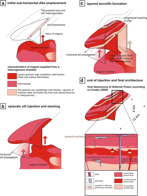
Schematic illustration of the multi-stage emplacement of the Götemar Pluton. See text for further explanation. Aplite and pegmatite dikes are only shown in d
-
2.
Multiple Si-metasomatic events and related crystallization of up to three generations of quartz are indicated by characteristic microfabrics: Metasomatic quartz replaces feldspar and mica crystals and produces grain-boundary instability in older quartz grains. In extreme cases, the resultant fabric consists of isolated mono- or poly-mineralic remnant grains embedded in large quartz grains. This is evidence for multiple Si-metasomatic events that originated from the residual melts of successive injections. A similar, but more intensive silicification related to granitic intrusions has been observed in metasediments of the Västervik Formation (Vollbrecht and Leiss 2008). Åhäll (2001) and Alm et al. (2005) revealed slight geochemical heterogeneities in terms of trace element distribution and SiO2 content within the overall homogeneous pluton. We suggest that these variations could also be secondary in origin, that is, due to metasomatism, as proposed above. This effect may have been enhanced by precipitation of secondary plagioclase, see below.
-
3.
Plagioclase/muscovite micro-veins: These crosscut with sharp boundaries saussuritized primary plagioclase grains, which clearly document metasomatic overprinting of already-lithified and even hydrothermally altered sills. Drake et al. (2009) related different types of comparable plagioclase and muscovite veins to the emplacement of the Götemar Pluton as a whole, that is to the circulation of its own post-magmatic fluids and a repeated tectonic overprinting in that area. In a multiple intrusion model that we propose, however, the described micro-veins may have formed in response to progressive injections of sills, which caused fracturing of older, completely lithified sills due to thermal or hydraulic stresses and supplied magmatic fluids.
-
4.
Microfabrics and CL patterns that display (high temperature) deformation of crystals and growth zoning of feldspars and quartz. The zoning observed in all crystals, resorbed and embayed margins, fibrous and corroded grain cores are indicative of dynamic, unstable, kinetically driven crystallization environments with highly variable order–disorder behaviour, which encourages a high defect density in the crystals (e.g. Slaby et al. 2008). The strongest resorption was documented in the fine-grained granite. The observed microfabrics are the result of dissolution (lack of equilibrium) and crystal growth after re-equilibration, caused by repeated influx of magma (magma mixing) in active and coherent magma domains with different melt fractions (Perugini et al. 2005) or infiltration of aqueous fluids. In the Götemar Pluton, crystals demonstrate syn-magmatic and solid-state deformation, which may be attributed to subsequent forceful magmatic injections. The corroded plagioclase probably originates from magma mixing in a chamber, while the mantle of the plagioclase crystallized after being pressed out of the mush during magma transport and final emplacement. Quartz and plagioclase grains that are simply zoned or lack growth zoning, but are highly resorbed and deformed, are restricted to fine-grained granite. Complex zoning and a large suite of replacement features are documented for the medium- to coarse-grained, thicker granite bodies.

Taken as a whole, these observations and earlier published data favour a model in which the upper crustal (4–8 km, Cruden 2008) Götemar Pluton was constructed by repeated, tabular, sill-like magma injections with variable melt fractions (layered laccolith, Fig. 10). Core data by Scherman (1978) confirm the horizontal zonation of the pluton.
The sharp intrusive contact (Drake and Tullborg 2006), without an observed contact aureole in the field, points to incremental emplacement of small magma volumes, with only small amounts of heat at any one time. The variations in the fabric of different sills, but with comparable compositions, can be attributed to several independent sources feeding from a heterogeneous main chamber with domains of variable melt fractions (Fig. 10). This is in agreement with models that suggest that a magma chamber can be regarded as a patchwork of melt-rich and melt-poor zones caused by remobilization of the crystal mush, triggered by magma replenishment throughout its lifetime (e.g. Miller et al. 2009). This would explain the different crystal contents (cf. Hildreth 2004) and the alternating, coarse-grained (up to several hundred metres thickness) and fine-grained granitic (around several tens of metres thickness) sill-like bodies in the pluton.
The Götemar Granite may have experienced magma mixing of different crystal/melt ratios that caused multiphase nucleation and episodes of slow crystal growth, as underlined by distinctive growth zoning in quartz and plagioclase, as well as the overprinting of previously emplaced sills by younger magma recharge events. In the latter case, groundmass quartz overgrew older generations during magma emplacement and cooling. Further evidence for recharge episodes is provided by, for example, corroded crystal cores in quartz and plagioclase, the fused and recrystallized domains, rounded and smudged growth zoning, and plagioclase mantles around alkali-feldspar phenocrysts that were related to changes in primary magma composition and environmental parameters (P, T, water content). This allowed plagioclase to nucleate on alkali-feldspar crystals (Hibbard 1981; Müller et al. 2005). Dempster et al. (1994) explained that the formation of a plagioclase mantle by redistribution of exsolved plagioclase from alkali-feldspar phenocrysts is linked to the high fluorine contents of magmas. This might well be the case of the Götemar Pluton, because it has a fluorine content of 0.35–0.5% (Alm and Sundblad 2002).
Ascent of magma probably occurred via a dike system (Fig. 10); the gravity profile shows a “thickened root zone” (Fig. 2; Cruden 2008). The initial emplacement of a sub-horizontal dike acted as a trap for the upward-propagating silicic magma (e.g. Kavanagh et al. 2006; Menand 2008; Miller et al. 2009). The laccolithic complex was progressively built by stacking and upward inflation of sills (e.g. Westerman et al. 2004; Morgan et al. 2008). The emplacement locations were probably controlled by structural heterogeneities in the TIB batholith (Cruden 2008) and/or by a stress field in which horizontal extensional fracturing could occur.
The described micro-structures and dike features are in accordance with an emplacement model of pluton growth by stacked intrusions that could occur without any tectonic influence. Therefore, we cannot imply a specific tectonic scenario nor position the Götemar Pluton within a particular geodynamic context. However, several authors have discussed the possibility that syn-tectonic emplacement of the Mesoproterozoic plutons was triggered by the onset of the distant Danopolian Orogeny (e.g. Bogdanova et al. 2001; Brander and Söderlund 2008; Zarins and Johansson 2008).
Conclusions
Field relationships between several generations of composite magmatic dikes and microfabrics indicative of complex crystallization and alteration history are interpreted as evidence of a multiple emplacement of the Götemar Pluton. The model implies a progressive stacking of sills, which were supplied from a heterogeneous main magma chamber that consisted of domains with varied melt fractions. During the growth of the pluton, earlier dikes/layers were altered by younger injections, which is indicated by, for example, polyphase silicification associated with replacement of primary minerals by quartz with different CL characteristics. Xenoliths that cannot be related to host rocks are interpreted as stoped blocks derived from lithified layers. Syn-magmatic crushing of phenocrysts and the lack of chilled margins points to high crystal fractions during ascent or final emplacement of individual layers. Likewise, the stepwise injection of small volumes of these magmas over a long time span can explain the lack of a significant contact aureole, because the corresponding heat from these pulses to the hot rock was comparatively low. Because of the inferred high crystal fraction during ascent and final emplacement, we ascribed complex microfabrics that indicate repeated magma mixing or fluid influx (e.g. growth zoning, overgrowth, corrosion) to the early history of the main magma chamber.
CL-microscopy is a very effective tool to visualize many phenomena such as growth zoning, chemical alteration and healed microfractures that cannot be detected by conventional optical microscopy and hence should become a standard method for fabric analysis of magmatites.
References
Åberg G (1978) Precambrian geochronology of southeastern Sweden. Geol Foren Stockh Forh 100:125–154
Åberg G (1988) Middle Proterozoic anorogenic magmatism in Sweden and worldwide. Lithos 21:279–289
Åberg G, Löfvendahl R, Levi B (1984) The Götemar Granite-isotopic and geochemical evidence for a complex history of an anorogenic granite. Geol Foren Stockh Forh 106:327–333
Åhäll K-I (2001) Åldersbestämning av svårdaterade bergarter i sydöstra Sverige. SKB-R-01–60. Swedish Nuclear Fuel and Waste Management Co, Stockholm, p 24
Åhall K-I, Conelly JN (2008) Long-term convergence along SW Fennoscandia: 330 m.y. of proterozoic crustal growth. Precambr Res 161:452–474
Åhall K-I, Larson SÅ (2000) Growth-related 1.85–1.55 Ga magmatism in the Baltic Shield: a review addressing the tectonic characteristics of Svecofennian TIB 1-related and Gothian events. Geol Foren Stockh Forh 122:193–206
Alm E, Sundblad K (2002) Fluorite-calcite-galena-bearing fractures in the countries of Kalmar and Blekinge, Sweden. SKB-R-02-42, Swedish Nuclear Fuel and Waste Management Co, Stockholm, p 116
Alm E, Sundblad K, Huhma H (2005) Sm–Nd Isotope determination of low-temperature fluorite–calcite–galena mineralization in the margins of the Fennoscandian Shield. SKB-R-05-55, Swedish Nuclear Fuel and Waste Management Co, Stockholm, p 48
Andersson UB, Rutanen H, Johansson Å, Mansfeld J, Rimša A (2007) Characterization of Paleoproterozoic mantle beneath the Fennoscandian Shield: geochemistry and isotope geology (Nd, Sr) of 1.8 Ga mafic plutonic rocks from the Transscandinavian igneous belt in Southeastern Sweden. Int Geol Rev 49:587–625
Bateman R (1985) Aureole deformation by flattening around a diapir during in situ ballooning: the Cannibal Creek Granite. J Geol 93:293–310
Bergman S, Hogdahl K, Nironen M, Ogenhall E, Sjostrom H, Lundqvist L, Lathinen R (1998) Timing of Palaeoproterozoic intra-orogenic sedimentation in the central Fennoscandian shield: evidence from detrital zircon in metasandstone. Precambr Res 161:231–249
Berry AJ, Walker AM, Hermann J, O′Neill HStC, Garry JF, Gale JD (2007) Titanium substitution mechanisms in forsterite. Chem Geol 242:176–186
Beunk FF, Page LM (2001) Structural evolution of the accretional continental margin of the Paleoproterozoic Svecofennian orogen in southern Sweden. Tectonophysics 339:67–92
Bogdanova SV, Page LM, Skridlaite G, Taran LN (2001) Proterozoic tectonothermal history in the western part of the East European Craton: 40/Ar/39Ar geochronological constraints. Tectonophysics 339:39–66
Brander L, Söderlund U (2008) Mesoproterozoic (1.47-1.44 Ga) orogenic magmatism in Fennoscandia; Baddeleyite U-Pb dating of a suite of massif-type anorthosite in S Sweden. Int J Earth Sci (Geol Rundsch) doi:10.1007/s00531-007-0281-0
Brown EH, McClelland WC (2000) Pluton emplacement by sheeting and vertical ballooning in part of the southeast Coast Plutonic Complex, British Columbia. Geol Soc Am Bull 112:708–719
Čečys A, Benn K (2007) Emplacement and deformation of the ca. 1.45 Ga Karlshamn granitoid pluton, southeastern Sweden, during ENE-WSW Danopolian shortening. Int J Earth Sci (Geol Rundsch) 96:397–414
Čečys A, Bogdanova S, Janson C, Bibikova E, Kornfält K-A (2002) The Stenshuvud and Tåghusa granitoids. New representatives of Mesoproterozoic magmatism in southern Sweden. Geol Foren Stockh Forh 124:149–162
Coleman DS, Gray W, Glazner AF (2004) Rethinking the emplacement and evolution of zoned plutons: geochronological evidence for incremental assembly of the Tuolumne Intrusive Suite, California. Geology 32:433–436
Cruden AR (2008) Emplacement mechanisms and structural influences of a younger granite intrusion into older wall rock-a principal study with application to the Götemar and Uthammar granites. SKB-R-08-138, Swedish Nuclear Fuel and Waste Management Co, Stockholm, p 48
Cruden AR, McCaffrey KJW (2001) Growth of plutons by floor subsidence: implications for rates of emplacement, intrusion spacing and melt-extraction mechanisms. Phys Chem Earth 26:303–315
Dempster TJ, Jenkin GRT, Rogers G (1994) The origin of rapakivi texture. J Petrol 35:963–981
Drachenfels von M-V (2004) Petrographie und Gefüge von Granitoiden der Västervik Region (SE-Schweden). Diploma thesis (unpubl), Georg-August University of Göttingen, p 139
Drake H, Tullborg E-L (2006) Fracture mineralogy of the Götemar granite: results from drill cores KKR01, KKR02 and KKR03. SKB-P-06-04, Swedish Nuclear Fuel and Waste Management Co, Stockholm, p 61
Drake H, Tullborg E-L, Page L (2009) Distinguished multiple events of fracture mineralisation related to far-field orogenic effects in Paleoproterozoic crystalline rocks, Simpevarp area, SE Sweden. Lithos 110:37–49
Fahlbusch W (2008) Strukturgeologische Analyse von Klüften und Mineralgängen im Götemargranit und seinen Rahmengesteinen. BSc thesis (unpubl), Georg-August University of Göttingen, p 52
Friese N, Vollbrecht A, Leiss B, Jacke O (2010) Cambrian sedimentary dikes in the Proterozoic basement of the Västervik area (Southeast Sweden): episodic formation inferred from macro- and microfabrics. Int J Earth Sci (Geol Rundsch) 100:741–752
Galadi-Enriquez E, Galindo-Zaldivar J, Simancas F, Exposito I (2003) Diapiric emplacement in the upper crust of a granitic body: the la Bazana granite. Tectonophysics 361:83–96
Ginibre C, Wörner G, Kronz A (2002) Minor- and trace-element zoning in plagioclase: implications for magma chamber process at Parinacota volcano, northern Chile. Contrib Mineral Petrol 143:300–315
Glazner AF, Bartley JM, Coleman DS, Taylor RZ (2004) Are plutons assembled over millions of years by amalgamation from small magma chambers? Geol Soc Am Today 14. doi: 10.1130/1052-5173(2004)014
Gorbatschev R, Bogdanova S (1993) Frontiers in the Baltic Shield. Precambr Res 64:3–12
Götze J, Habermann D, Neuser RD, Richter DK (1999) High-resolution spectrometric analysis of rare earth elements-activated cathodoluminescence in feldspar minerals. Chem Geol 153:81–91
Götze J, Krbetschek MR, Habermann D, Wolf D (2000) High-resolution cathodoluminescence of feldspar minerals. In: Pagel M, Barbin V, Blanc P, Ohnenstetter D (eds) Cathodoluminescence in Geosciences. Springer, Berlin, pp 245–270
Götze J, Plötze M, Habermann D (2001) Origin, spectral characteristics and practical applications of the cathodoluminescence (CL) of quartz: a review. Mineral Petrol 71:225–250
Hermann J, O′Neill HStC, Berry AJ (2005) Titanium solubility in olivine in the system TiO2-MgO-SiO2: no evidence for an ultra-deep origin of Ti-bearing olivine. Contrib Mineral Petrol 148:746–760
Hibbard MJ (1981) The magma mixing origin of mantled feldspars. Contrib Mineral Petrol 76:158–170
Hildreth W (2004) Volcanological perspectives on Long Valley, Mammoth Mountain, and Mono Craters: several contiguous but discrete systems. J Volcanol Geotherm Res 136:169–198
Hjelt SE, Daly S (2004) SVEKALAPKO. Evolution of Paleoproterozoic and Achaean Lithosphere. (http://www.geofys.uu.se)
Högdahl K, Andersson UB, Eklund O (2004) The Transscandinavian Igneous Belt (TIB) in Sweden: a review of its character and evolution. Geol Surv Finland Spec Pap 37:125
Horsman E, Morgan S, St-Blanquat M, Habert G, Hunter R, Nugent A, Tikoff B (2009) Emplacement and assembly of shallow plutons through multiple magma pulses, Henry Mountains, Utah. Trans R Soc Edinb 100:117–132
Hövelmann J, Putnis A, Geisler T, Schmidt BC, Golla-Schindler U (2010) The replacement of plagioclase feldspar by albite: observations from hydrothermal experiments. Contrib Mineral Petrol 159:43–59
Kavanagh JL, Menand Th, Sparks RSJ (2006) An experimental investigation of sill formation and propagation in layered elastic media. Earth Planet Sci Lett 245:799–813
Kornfält K-A, Persson P-O, Wikman H (1997) Granitoids from the Äspö area, southeastern Sweden-geochemical and geochronological data. Geol Foren Stockh Forh 119:109–114
Kresten P, Chyssler J (1976) The Götemar massif in south-eastern Sweden: a reconnaissance survey. Geol Foren Stockh Forh 98:155–161
Krumbholz M (2010) Electromagnetic Radiation as a tool to determine actual crustal stresses—applications and limitations. PhD thesis, Georg-August University of Göttingen, p 150
Küstner W (1994) Mittelproterozoische Magmatite im “Transscandinavian Granite-Porphyry Belt” NE′ des Götemar Sees, SE-Schweden. Diploma mapping (unpubl.), Georg-August University of Göttingen, p 65
Larsen O (1971) K/Ar age determinations from Precambrian of Denmark. Geol Surv Denmark. II Series 97
Lee MR, Parsons I, Edwards PR, Martin RW (2007) Identification of cathodoluminescence activators in zoned alkali-feldspars by hyperspectral imaging and electron-probe microanalysis. Am Mineral 92:243–253
Lindroos H (2004) The potential for ore, industrial minerals and commercial stones in the Simpevarp area. SKB-R-04-72, Swedish Nuclear Fuel and Waste Management Co, Stockholm, p 48
London D (2005) Granitic pegmatites: an assessment of current concept and directions for the future. Lithos 80:281–303
Mahon KI, Harrison TM, Drew DA (1988) Ascent of a granitoid diapir in a temperature varying medium. J Geophys Res 93:1174–1188
Mainprice D, Bouchez J-L, Blumenfeld P, Tubia J (1986) Dominant c-slip in naturally deformed quartz: implications for dramatic plastic softening at high temperatures. Geology 14:819–822
Mansfeld J, Beunk FF, Barling J (2005) 1.83–1.82 Ga formation of a juvenile volcanic arc—implications from U-Pb and Sm-Nd analyses of the Oskarshamn-Jönköping Belt, southeastern Sweden. Geol Foren Stockh Forh 127:149–157
Marsh BD (1982) On the mechanics of igneous diapirism, stoping, and zone melting. Am J Sci 282:808–855
Matzel JEP, Bowring SA, Miller RB (2006) Time scales of pluton construction at differing crustal levels; examples from the Mount Stuart and Ten Peak Intrusions, north Cascades, Washington. Geol Soc Am Bull 118:1412–1430
Menand T (2008) The mechanics and dynamics of sills in layered elastic rocks and their implications for the growth of laccoliths and other igneous complexes. Earth Planet Sci Lett 267:93–99
Meunier JD, Sellier E, Pagel M (1990) Radiation-damage rims in quartz from uranium-bearing sandstones. J Sed Petrol 60:53–58
Miller CF, Furbish DJ, Walker BA, Claiborne LL, Koteas GC, Bleick HA, Miller JS (2009) Growth of plutons by incremental emplacement of sheets in crystal-rich host: evidence from Miocene intrusions of the Colorado River region, Nevada. doi:10.1016/j.tecto.2009.07.011
Molyneux SJ, Hutton DHW (2000) Evidence for significant granite space creation by the ballooning mechanism: the example of the Ardara pluton, Ireland. Geol Soc Am Bull 112:1543–1558
Morad S, El-Ghali MAK, Caja MA, Sirat M, Al-Ramadan K, Mansurbeg H (2010) Hydrothermal alteration of plagioclase in granites from Proterozoic basement of SE Sweden. Geol J 45:105–116
Morgan S, Stanik A, Horsman E, Tikoff B, de Saint-Blanquat M, Habert G (2008) Emplacement of multiple magma sheets and wall rock deformation: Trachyte mesa intrusion, Henry Mountains, Utah. J Struct Geol 30:491–512
Müller A (2000) Cathodolominescence and characterisation of defect structures in quartz with applications to the study of granitic rocks. PhD thesis, Georg-August University of Göttingen, p 228
Müller A, Breiter K, Seltmann R, Pécskay Z (2005) Quartz and feldspar zoning in the eastern Erzgebirge volcano–plutonic complex (Germany, Czech Republic): evidence of multiple magma mixing. Lithos 80:201–227
Neuser RD, Bruhn F, Habermann D, Richter DK (1995) Kathodolumineszenz: Methodik und Anwendung. Zentralbl Geol Paläont I 1(2):287–306
Nolte N, Kleinhans IC, Bäro W, Hansen BT (2008) An evolutionary model of 1,8 Ga granitoids of the Västervik area (SE Sweden) based on a refined geological map. 86th Annual Meeting of the German Mineralogical Society, DMG, Berlin, Sep 14th–17th 2008, Abstr S07-275
Page L, Söderlund P, Wahlgren C-H (2007) 49Ar/39Ar and (U-Th)/He geochronology of samples from the cored boreholes KSH03A, KSH03B, KLX01, KLX02 and the access tunnel to the Äspö Hard Rock Laboratory. SKB-P07-160, Swedish Nuclear Fuel and Waste Management Co, Stockholm, p 48
Pagel M, Barbin V, Blanc P, Ohnstetter D (2000) Cathodoluminescence in geosciences. Springer, Berlin
Parsons I, Steele D, Lee MR, Magee CW (2008) Titanium as a cathodoluminescence activator in alkali feldspar. Am Mineral 93:875–879
Passchier CW, Trouw RAJ (1998) Microtectonics 2nd edn. Springer, p 283
Paterson SR, Vernon RH (1995) Bursting the bubble of ballooning plutons; a return to nested diapirs emplaced by multiple processes. Geol Soc Am Bull 107:1356–1380
Paterson SR, Pignotta GS, Vernon RH (2004) The significance of microgranitoid enclave shapes and orientations. J Struct Geol 26:1465–1481
Paterson SR, Pignotta GS, Farris D, Memeti V, Miller RB, Vernon RH, Zak J (2008) Is stoping a volumetrically significant pluton emplacement process?: Discussion. Geol Soc Am Bull 120(7/8):1075–1079
Perugini D, Poli G, Valentini L (2005) Strange attractors on plagioclase oscillatory zoning: petrological implications. Contrib Min Petrol 149:482–497
Pinotti LP, Coniglio JE, Esparza AM, D′Eramo FJ, Llambías EJ (2002) Nearly circular plutons emplaced by stoping at shallow crustal levels, Cerro Aspero batholith, Sierras Pampeanas de Cordoba, Argentina. J South Am Earth Sci 15:251–265
Plümer O, Putnis A (2009) The complex hydrothermal history of granitic rocks: multiple feldspar replacement-reactions under sub-solidus conditions. J Petrol 50(5):967–987
Ramsay JG (1989) Emplacement kinematics of a granite diapir: the Chindamora batholith, Zimbabwe. J Struct Geol 11:191–209
Röshoff K, Cosgrove J (2002) Sedimentary dikes in the Oskarshamn-Västervik area—a study of the mechanisms of formation. SKB Rapport R-02-37, Swedish Nuclear Fuel and Waste Management Co, Stockholm, p 98
Rusk BG, Reed MH, Dilles JH, Kent AJR (2006) Intensity of quartz cathodoluminescence and trace-element content in quartz from the porphyry copper deposit at Butte, Montana. Am Mineralog 91:1300–1312
Saint Blanquant M, de Law RD, Bouchez J-L, Morgan SS (2001) Internal structure and emplacement of the Papoose Flat Pluton: an integrated structural, petrographic, and magnetic susceptibility study. Geol Soc Am Bull 113(8):976–995
Scherman S (1978) Förarbeten för platsval, berggrundsundersökningar. SKB Technical report 60, Swedish Nuclear Fuel and Waste Management Co, Stockholm, p 223
SKB-R-02-35 (2002) Simpevarp-site descriptive model version 0. Swedish Nuclear Fuel and Waste Management Company. SKB-R-02-35. Stockholm, p 151
Slaby E, Götze J (2004) Feldspar crystallization under magma-mixing conditions shown by cathodoluminescence and geochemical modelling–a case study from the Karkonosze pluton (SE Poland). Mineral Mag 68:561–577
Slaby E, Galbarczyk-Gasiorowska L, Baszkiewicz A (2002) Mantled alkali-feldspar megacrysts from the marginal part of the Karkonosze granitoid massif. Acta Geol Pol 52(4):501–519
Słaby E, Galbarczyk-Gąsiorowska L, Seltmann R, Müller A (2007) Alkali feldspar megacryst growth: geochemical modelling. Min Petrol 89:1–29
Slaby E, Götze J, Wörner G, Simon K, Wrzalik R, Smigielski M (2008) K-feldspar phenocrysts in microgranular magmatic enclaves: a cathodoluminescence and geochemical study of crystal growth as a marker of magma mingling dynamics. Lithos 105:85–97
Söderlund P, Page L, Söderlund U (2008) 40Ar/39Ar biotite and hornblende geochronology from the Oskarshamn area, SW Sweden: discerning multiple Proterozoic tectonothermal events. Geol Mag. doi:10.1017/S0016756808005001
Sprunt E (1981) Causes of quartz cathodoluminescence colours. Scan Electron Microsc 1981:525–535
Stull RJ (1979) Mantled feldspars and synneusis. Am Min 64:514–518
Sultan L, Plink-Björklund P (2006) Depositional environments at a Palaeoproterozoic continental margin, Västervik Basin, SE Sweden. Precambr Res 145:243–271
Sultan L, Claesson S, Plink-Björklund P (2005) Proterozoic and Archaean ages of detrital zircon from the Palaeoproterozoic Västervik Basin, SE Sweden: implications for provenance and timing of deposition. Geol Foren Stockh Forh 127:17–24
Sylvester AG, Oertel G, Nelson CA, Christie JM (1978) Papoose flat pluton: a granitic blister in the Inyo mountains, California. Geol Soc Am Bull 89:1205–1219
Szagun U (1997) Mikrorisse in Graniten der Transskandinavischen Magmatischen Zone (Gebiet zwischen Västervik und Oskarshamn). Diploma thesis (unpubl), University of Göttingen, p 68
Triumf C-A (2004) Gravity measurements in the Laxemar model area with surrounding. Swedish Nuclear Fuel and Waste Management Company. SKB-P-04-128, Stockholm, Sweden, p 40
Viola G, Ganerød GV (2007) Structural analysis of brittle deformation zones in the Simpevarp-Laxemar area, Oskarshamn, southeast Sweden. Swedish Nuclear Fuel and Waste Management Company. SKB-P-07–41, Stockholm, p 77
Vollbrecht A, Leiss B (2008) Complex fabric development in Paleoproterozoic meta-quartzites of the Västervik Basin, SE Sweden. Geol Foren Stockh Forh 130:41–45
Wahlgren C-H, Ahl M, Sandahl K-A, Berglund J, Petersson J, Ekström M, Persson P-O (2004) Oskarshamn site investigation. Bedrock mapping 2003–Simpevarp subarea. Outcrop data, fracture data, modal and geochemical classification of rock types, bedrock map, radiometric dating. Swedish Nuclear Fuel and Waste Management Company. SKB-R-04–102, Stockholm, p 59
Wahlgren C-H, Hermanson J, Forssberg O, Curtis P, Triumf C-A, Drake H, Tullborg E-L (2006) Geological description of rock domains and deformation zones in the Simpevarp and Laxemar subareas. Preliminary site description Laxemar subarea-version 1.2. Swedish Nuclear Fuel and Waste Management Company. SKB-R-05-69, Stockholm, Sweden, 271 p
Wark DA, Spear FS (2005) Titanium in quartz: cathodoluminescence and thermometry. Geochim Cosmochim Acta 69:A592
Weidemann M (2008) Strukturgeologische Analyse von Magmatit- und Sedimentgängen im Götemar-Granit und seinen Rahmengesteinen. BSc thesis (unpubl), Georg-August University of Göttingen, 43 p
Weinberg RF (1996) Ascent mechanism of felsic magmas: news and views. Trans R Soc Edinb Earth Sci 87:95–103
Westerman DS, Dini A, Innocenti F, Rocchi S (2004) Rise and fall of a nested Christmas-tree laccolith complex, Elba Island, Italy. In: Breitkreuz C, Petford N (eds) Physical geology of high-level magmatic systems. J Geol Soc London Spec Pub 234:195–213
Whalen JB, Currie KL, Chappell BW (1987) A-type granites: geochemical characteristics, discrimination and petrogenesis. Contrib Mineral Petrol 95:407–419
White WB, Masako M, Linnehan DG, Furukawa T, Chandrasekhar BK (1986) Absorption and luminescence of Fe3+ in single-crystal orthoclase. Am Mineral 71:1415–1419
Wiebe RA, Wark DA, Hawkins DP (2007) Insights from quartz cathodoluminescence zoning into crystallization of the Vinalhaven granite, coastal Maine. Contrib Mineral Petrol 154:439–453
Wikman H, Kornfält K-A (1995) Updating of a lithological model of the bedrock of the Äspö area. Swedish Nuclear Fuel and Waste Management Company. SKB-PR 25-95-04, Stockholm
Zarins K, Johansson Å (2008) U-Pb geochronology of gneisses and granitoids from the Danish island of Bornholm: new evidence for 1.47-1.45 Ga magmatism at the southwestern margin of the East European Craton. Int J Earth Sci. doi:10.1007/s00531-008-0333-0
Acknowledgments
We thank the reviewers C.F. Miller and E. Slaby for their constructive reviews, W.-C. Dullo and M. Elburg are acknowledged for their editorial handling of the manuscript. We are grateful for discussions with A. Müller (NGU), N. Nolte (University of Göttingen) and S. Burchardt (University of Uppsala). A. van den Kerkhof (University of Göttingen) is thanked for help with the CL analysis and the discussion in this paper. A.R. Cruden (University of Toronto) and C- H Wahlberg (SKB, Sweden) are acknowledged for their help with literature research. We also thank M. de Saint-Blanquat and an anonymous reviewer for their helpful and constructive comments on an earlier version of the manuscript.
Open Access
This article is distributed under the terms of the Creative Commons Attribution Noncommercial License which permits any noncommercial use, distribution, and reproduction in any medium, provided the original author(s) and source are credited.
Author information
Authors and Affiliations
Corresponding author
Rights and permissions
Open Access This is an open access article distributed under the terms of the Creative Commons Attribution Noncommercial License (https://creativecommons.org/licenses/by-nc/2.0), which permits any noncommercial use, distribution, and reproduction in any medium, provided the original author(s) and source are credited.
About this article
Cite this article
Friese, N., Vollbrecht, A., Tanner, D.C. et al. Multi-stage emplacement of the Götemar Pluton, SE Sweden: new evidence inferred from field observations and microfabric analysis, including cathodoluminescence microscopy. Int J Earth Sci (Geol Rundsch) 101, 1149–1167 (2012). https://doi.org/10.1007/s00531-011-0739-y
Received:
Accepted:
Published:
Issue Date:
DOI: https://doi.org/10.1007/s00531-011-0739-y