Abstract
This paper introduces a novel method for solving the resection problem in two and three dimensions based on conformal geometric algebra (CGA). Advantage is taken because of the characteristics of CGA, which enables the representation of points, lines, planes, and volumes in a unified mathematical framework and offers a more intuitive and geometric understanding of the problem, in contrast to existing purely algebraic methods. Several numerical examples are presented to demonstrate the efficacy of the proposed method and to compare its validity with established techniques in the field. Numerical simulations indicate that our vector geometric algebra implementation is faster than the best-known algorithms to date, suggesting that the proposed GA-based methods can provide a more efficient and comprehensible solution to the two- and three-dimensional resection problem, paving the way for further applications and advances in geodesy research. Furthermore, the method’s emphasis on graphical and geometric representation makes it particularly suitable for educational purposes, allowing the reader to grasp the concepts and principles of resection more effectively. The proposed method has potential applications in a wide range of other fields, including surveying, robotics, computer vision, or navigation.
1 Introduction
The resection problem, also known in surveying as the Snellius–Pothenot (SP) or the inverse intersection problem, involves calculating the position of an unknown point P (also called a station) using the positions of three known points A, B, and C, and relative angular measurements from P. It is a relevant problem not only in geodesy and surveying, but also in other disciplines such as robot path planning (Masselli and Zell 2014), positioning (Pierlot and Van Droogenbroeck 2014), navigation (Pereira et al. 2018) or computer graphics (Mazaheri and Habib 2015), and can be solved both geometrically and algebraically. The solution of the two-dimensional problem has been known for several centuries and has numerous variants [almost 500! according to Bock (1956)]. The three-dimensional problem is much more intricate and only complex and sophisticated algebraic solutions are known. The two- and three-dimensional configurations are illustrated in Fig. 1.
1.1 Motivation
The determination of the position of an observer based on angular measurements from known points is of interest in several disciplines, such as surveying, computer graphics, optics, and robotics. Traditionally, solutions to this problem have relied on heavily algebraically loaded methods, which can be complex and challenging to comprehend. Furthermore, these methods do not always provide an intuitive understanding of the geometric relationships involved in the problem.
In both two-dimensional (2D) and three-dimensional (3D) problems, there is a need for a more geometric or graphical approach that simplifies the study of the resection problem. Although there are existing graphical methods for solving the problem in 2D that have been known for some time, their algebraic implementation can be quite cumbersome, hindering their widespread adoption. When the problem is approached from a geometric perspective, a better understanding of the underlying structures and relationships can be achieved, making the problem more accessible to a wider range of researchers and practitioners. This could potentially lead to novel applications and advancements in the related areas mentioned above.
In light of the exposed ideas, the main motivation behind this paper is to develop a novel geometric method based on conformal geometric algebra (CGA) to address the resection problem in two- and three-dimensional ways. By leveraging the unifying properties of CGA to represent geometric primitives within a single mathematical framework, we aim to provide a more intuitive and geometric understanding of the problem, simplifying its study, and paving the way for further applications and advancements in the field.
1.2 Background and literature overview
The resection problem has been extensively studied in the literature, with various algebraic and geometric or graphical methods proposed for its solution. It appears that ancient Greeks, such as Hipparchus or Ptolemy, already studied this problem in the context of astronomy, although the first person to solve the problem in the context of surveying was the Dutch mathematician Willebrord Snel van Royen (known as Snellius) in 1617 (Wreede 2007). He achieved the goal by using geometric and algebraic methods mainly based on trigonometry. This same problem was addressed in 1671 by John Collins in his work Philosophical Transactions. Collins contributed significantly to the topic by presenting a new and elegant geometrical solution, which involves the use of just one circle and an auxiliary point. In 1692, Laurent Pothenot, who was working on the definition of the meridian north of Paris, presented a paper on the subject. However, according to McCaw (1918) and others, Pothenot did not contribute anything new to the solution of the problem and all he did was publish the works of Snellius and Collins under his own name. Other authors who have studied this issue are shown in Table 1.
In the context of geodesy and surveying, the resection problem has been a fundamental problem for centuries. The problem has been addressed from various perspectives, including algebraic (Awange et al. 2010), geometric/graphical (Masselli and Zell 2014), and numerical (Dekov 2012) methods. Algebraic solutions to the problem are well established and have been extensively studied. However, these methods often involve complex algebraic manipulations and do not provide any intuitive geometric understanding of the problem.
The two-dimensional problem has been solved using approaches such as graphical methods (Bock 1956), analytical geometry (Bil 1992), matrix methods (Bähr 1991), and algebraic methods based on Sylvester resultants (Awange and Grafarend 2002), Groebner bases (Awange 2002), and other elimination techniques (Sturmfels 2002). Awange and Grafarend (2005) provided a detailed overview of several algebraic techniques for solving 2D and 3D resection.
The three-dimensional version is more complex, with most solutions relying on intricate algebraic methods. Grunert originally formulated the problem in 1841 and derived quartic equations to determine the unknown distances (Grunert 1841). Since then, numerous procedures have been developed to optimise Grunert’s formulation and reduce the computational steps involved (Awange and Grafarend 2005; Fischler and Bolles 1981). Algebraic techniques such as Groebner bases (Awange and Grafarend 2003a), polynomial resultants (Awange and Grafarend 2003b), and linear homotopy (Paláncz et al. 2010) have been effectively applied to solve the 3D problem. However, geometric solutions to the resection problem have been less explored. The geometric or graphical approach provides a more intuitive understanding of the problem and can be more easily visualised.
In recent years, there has been a growing interest in the application of geometric algebra (GA) to solve several geometric problems. GA provides a unified mathematical framework for representing and manipulating geometric objects, making it a powerful tool for geometric computations (Dorst et al. 2010). The application of GA to the resection problem was first proposed by Smith (2023b, 2023a).
However, the application of GA to the resection problem is still in its early stages, and there is still a long way to go. In particular, the application of conformal geometric algebra (CGA) to the resection problem has not been fully explored. CGA extends GA by incorporating the concept of conformal transformations, which can provide a more powerful and flexible framework for geometric computations (Hestenes and Sobczyk 2012; Dorst et al. 2010). CGA provides a unified framework for handling points, lines, planes, circles, spheres, and other geometric entities. Each entity has a unique representation, and the relationships between entities correspond to algebraic relationships between their CGA representations. This eliminates the need for coordinate transformations when transitioning between reference frames.
Cameron and Lasenby (2008) showed that CGA subsumes projective geometry and is more computationally efficient than matrix methods. CGA has found applications in computer vision (Wareham et al. 2004), robotics (Zaplana et al. 2022), and other geometric computing problems (Hitzer et al. 2022). However, its potential for solving resection-type problems in geodesy and surveying remains relatively unexplored. This paper seeks to fill the void by introducing a new geometric solution based on CGA for the 2D and 3D resection problem.
1.3 Contributions
In this paper, a new method for solving the resection problem using the mathematical framework geometric algebra in 2D and 3D dimensions is proposed. The method provides a simple solution based on purely geometric and graphical principles. Specifically, the 3D version of the problem is thoroughly analysed in detail. Specific novel contributions are the following:
-
A novel conformal geometric algebra (CGA)-based method is presented to solve the two- and three-dimensional resection problem, providing a more intuitive and unified geometric approach.
-
The proposed method is compared with established techniques, and its advantages and efficacy are demonstrated through numerical examples.
-
The potential applications of the method in several fields such as computer graphics, optics, and robotics are highlighted, emphasising its versatility, and paving the way for future advancements in geometric research.
-
Several algorithms have been developed that provide better results than the best-known algorithms to date from a computational perspective.
1.4 Outline
The remainder of the article is organised as follows. Section 2 provides an introduction to geometric algebra and conformal geometric algebra. Section 3 revisits the resection problem and reviews traditional methods. Section 4 presents existing and new GA-based methods. Section 4 presents the proposed method based on CGA to solve the resection problem. Section 5 provides several application examples to demonstrate the effectiveness of the proposed method, along with benchmarks for computational efficiency. Section 6 provides an error and uncertainty analysis of the proposed methods. Finally, Sect. 7 concludes the article with a summary and some suggestions for future work.
2 Basics concepts in geometric algebra
Geometric algebra is a mathematical framework for representing geometric objects and transformations in a unified way (Hestenes and Sobczyk 2012). GA extends the algebra of vectors to include other geometric objects such as points, lines, planes, and volumes. GA provides a powerful tool to solve geometric problems and has applications in a wide range of fields, including electrical engineering (Montoya et al. 2019, 2021), computer vision (Hrdina and Návrat 2017), robotics (Hrdina et al. 2017), and other engineering fields [see Hitzer et al. (2022) and references there in].
GAs are used mainly in situations where Euclidean transformations play a significant role. A simple way to introduce GAs is to understand them through more familiar tools such as complex numbers or quaternions (indeed, they are subalgebras of GA). For example, implementing Euclidean rotations using quaternions is essential to improve computational capabilities and adopt an object-oriented approach. We can see quaternions \({\mathbb {H}}\) as a natural extension of the complex numbers \({\mathbb {C}}\) in the form
where \(a,b,c,d \in \mathbb R\) and the products of the basis elements \(\varvec{i},\varvec{j},\varvec{k}\) satisfy the multiplications rules \(\varvec{i}^2=\varvec{j}^2=\varvec{k}^2=-1\) and \(\varvec{ij}=-\varvec{ji}=\varvec{k}\). The quaternion \(\text {Im} (\varvec{z})=b \varvec{i} + c \varvec{j} +d\varvec{k}\) is called the imaginary part of \(\varvec{z}\), and \(\text {Re} (\varvec{z})=a\) is called the real part of \(\varvec{z}\). Note the use of bold letters for quaternions and regular font for real numbers.
The operation of rotating an object by an angle \(\theta \) around the axis \(\varvec{n}= n_x \varvec{i}+ n_y \varvec{j}+ n_z \varvec{k} \) can be represented by the quaternion
acting on the vector \(\varvec{q}= x\varvec{i} +y\varvec{j} +z\varvec{k}\). Note that \(||\varvec{n}||=\sqrt{\varvec{n}\bar{\varvec{n}}}=1\), where the bar decoration stands for quaternionic conjugation. The representation is done in a similar way as in the case of complex numbers. The difference is that quaternions are not commutative and thus they act via the so-called sandwich product
So, we are working in a four-dimensional linear space. If we want to realise also the translations, we have to extend the algebra by another dimension using an element \(\varvec{\epsilon }\) such as \(\varvec{\epsilon }^2=0\) and \(\varvec{\epsilon } \varvec{i}=\varvec{\epsilon } \varvec{j}=\varvec{\epsilon } \varvec{k}=0\). This algebra is usually called dual quaternions. For more on the use of quaternions in general engineering topics, see Selig (2005).
On the other hand, the wedge operation on a vector space allows us to work with linear subspaces. A line can be characterised by a vector \(\varvec{\ell }\), so x belongs to a line if and only if \(x \wedge \varvec{\ell }=0\). The wedge of two vectors then characterises the plane in the same way. A vector space closed in the wedge operation is called a Grassmannian algebra. The combination of these two concepts leads to the notion of GA.
2.1 Euclidean vector GA
Vector geometric algebra (VGA) is perhaps one of the simplest GAs. For the two-dimensional case, the VGA (\(\mathbb G_2\)) is a Grassmannian algebra based on two orthonormal basis vectors (\(\varvec{\sigma }_1\), \(\varvec{\sigma }_2\)) together with a bilinear operation known as geometric product satisfying the following identities:
The term \(\varvec{\sigma }_1 \wedge \varvec{\sigma }_2\) is known as bivector (\(\varvec{\sigma }_{12}\) for short). Geometrically, a bivector represents an oriented plane segment spanned by the two vectors. We can use bivectors to represent rotations in the following way. The collection of bivectors \(\varvec{\sigma }_1 \wedge \varvec{\sigma }_2\) forms a one-dimensional vector space that is closed under multiplication. We can then generate rotations by applying the exponential map to bivectors. For example, the exponential of the bivector
is used as in (3) to perform a rotation by an angle \(\theta \) in the plane spanned by \(\varvec{\sigma }_1\) and \(\varvec{\sigma }_2\). In this way, the group of rotations generated by the bivectors is mathematically equivalent to the group of unitary complex numbers \(e^{i\theta }\), which also represent rotations in the complex plane (note that \((\varvec{\sigma }_1 \wedge \varvec{\sigma }_2 )^2 =-1\)). However, bivectors provide a more intuitive geometric representation of rotations directly in vector space.
Similarly, we can introduce the \(\mathbb G_3\) algebra for the purposes of reasoning in the 3D space. The algebra \(\mathbb G_3\) is based on three generators \(\varvec{\sigma }_1, \varvec{\sigma }_2\) and \(\varvec{\sigma }_3\) together with a geometric product defined by the following identities:
In Sect. 4.1, it will be shown how to use the VGA-based method to solve a 2D version of the resection problem. This procedure is, in fact, a use of GA \(\mathbb G_2\).
2.2 Conformal geometric algebra
The goal here is to create a model of Euclidean geometry. Specifically, geometry whose symmetry group contains the Euclidean symmetries (rotations, translations, etc.). For that purpose, a nondegenerate quadratic form will be chosen, thus obtaining the conformal geometric algebra (CGA). In the case of CGA for a two-dimensional Euclidean space, a GA of signature (3, 1) is obtained [also known as Compass Rule Algebra CRA, see Hildenbrand (2018)], with basis vectors \(\varvec{\sigma }_1,\varvec{\sigma }_2,\varvec{\sigma }_+\) and \(\varvec{\sigma }_-\) such that
For mathematical convenience, it is advisable to define two new basis vectors
with properties
Vector \(\varvec{\sigma }_0\) is known to represent the Euclidean point at the origin of the coordinate system, and vector \(\varvec{\sigma }_{\infty }\) represents the point at infinity. Using the rules above, it can be proved that any Euclidean point X can be mapped to the CGA vector space as
In “Appendix A.1”, explicit calculations that justify our choices can be found. As in Sect. 2.1, the extension to higher dimensions is straightforward by adding the element \(\varvec{\sigma }_3\). This will make \(\mathbb G_3\) appear instead of \(\mathbb G_2\), and quaternions will appear in the bivectors.
In the notation used throughout this paper to ensure clarity, regular font indicates real numbers, boldface denotes vectors in the CGA space, boldface with an overhead arrow (e.g. \(\vec {\varvec{x}}\)) represents vectors in the Euclidean space, and uppercase letters in boldface indicate multivectors in CGA.
The usefulness of CGA and CRA is based on the fact that the distance between Euclidean points is encoded in the scalar product. The points X and Y are represented by the Euclidean vectors \(\vec {\varvec{x}}\) and \(\vec {\varvec{y}}\), respectively. The mapping defined in (12) maps these Euclidean points (vectors) to vector elements \(\varvec{{x}}\) and \(\varvec{{y}}\) in the CGA space.
As shown in “Appendix A.2”, the scalar product between two CGA points codes the distance:
Thus, the Euclidean point X (represented by the Euclidean vector \(\vec {\varvec{x}}\)) lies on the sphere (circle) S with centre in point C and radius r if and only if it satisfies the identity \(\varvec{{x}} \cdot \varvec{{c}} = -\frac{1}{2} r^2 \) in the conformal space. Since \(\varvec{x}\cdot \varvec{\sigma }_{\infty }=-1\) for each point, this identity may be written as
Thus, the vector element \(\varvec{{c}} - \frac{1}{2} r^2 \varvec{\sigma }_{\infty } \) represents the sphere S in the CGA space. It should be emphasised that within CGA, there exist two distinctive methods to reference the identical geometric entity: IPNS and OPNS (see “Appendix A.3”). IPNS is superior for transformations and intersections, whereas OPNS is advantageous for blending and morphing tasks. It is crucial to be aware of the representation we are operating in; however, transitioning between representations can be achieved seamlessly using the dual operator (\(^\star \)), as described in “Appendix A.3”.
3 Revisiting the resection problem
In the context of geodesy and surveying, the resection problem plays an important role in determining the position of an observer based on angular measurements from three known reference points. Over the years, various approaches have been developed to address this problem, ranging from graphical or geometrical methods to algebraic ones. However, many of these methods can be complex or tedious, particularly when addressing the problem in three dimensions. With the growing importance of accurate positioning in modern applications, it is essential to revisit the resection problem and explore innovative approaches that offer more intuitive solutions.
3.1 Traditional methods
In this section, traditional methods for solving the resection problem are reviewed. They can be classified into four basic groups: trigonometric, geometric/graphical, iterative (numerical) and others (see Table 2). A comprehensive list of methods for 2D resection problems is already presented in Table 1. Note that sometimes the frontier between trigonometric and geometric methods is not as clear because both solutions exist at the same time (e.g. the Cassini method).
Trigonometric methods are some of the oldest and most famous procedures for solving the 2D resection problem. They are based on the use of trigonometric functions to compute the position of the observer using the angles between the known points and the observer.
The Pothenot–Snellius method, also known as the Kästner–Burkhardt method, is one of the most known and oldest procedures in this group. The Cassini method is another example of a trigonometric solution (with a graphical solution, too), which is similar to the one described by Esteves et al. and Cohen and Koss. The Easton and Cameron method is also a trigonometric approach, similar to the Cassini method.
Geometric or graphical methods, on the other hand, use geometrical constructions and properties of the known points to calculate the position of the observer. These methods are based on the use of geometric and graphic principles to solve the problem. Esteves et al. proposed a geometric method that uses the intersection of circles to calculate the position of the observer. Cohen and Koss also proposed a geometric method that uses the intersection of circles, but with a different approach from Esteves et al. Font-Llagunes proposed a method that uses the intersection of lines and similarity between triangles to calculate the position of the observer. Pierlot et al. and Ligas proposed a method that uses the intersection of power lines to calculate the position of the observer, although the solution is given in algebraic form.
Iterative methods use iterative algorithms to converge to the observer position. These methods are based on the use of an initial estimate of the observer position, which is refined iteratively until convergence is achieved. Iterative search is an example of an iterative method that uses a search algorithm to find the robot position. Sanchiz et al. proposed a method that uses an iterative search algorithm to find the observer position.
Finally, there are other methods that do not fit the previous groups. The Tienstra method is one such example, which is a completely different approach based on barycentric coordinates. Another method like Willerding is based on the use of complex numbers to compute rotations in the Argand plane to find the observer position.
4 Resection using geometric algebra
Nowadays, methods based on geometric algebra (GA) have been developed, providing a new solution to the resection problem while maintaining the focus on its geometrical roots. GA offers a versatile framework that can be adapted to different contexts based on the selection of specific metrics and the number of dimensions. For example, when all elements of the base \(\varvec{\sigma }_i\) square to \(+1\), the resulting algebra is known as vector geometric algebra (VGA) (see Sect. 2.1). By extending the ability of the basis elements to square to \(-1\) or 0 or by accommodating more dimensions, it becomes possible to explore alternative forms of GA. One such example is CGA, which incorporates two additional dimensions: one dimension squaring to \(+1\) and another squaring to \(-1\). This flexibility enables GA to solve a wide array of applications and problem domains, seamlessly scaling the number of dimensions in a straightforward way.
4.1 Vector GA method
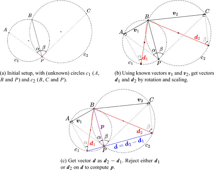
The 2D VGA-based method has been recently proposed by Smith (2023a) and published as disseminative material. The process is mainly geometric and results in obtaining a vector \(\varvec{p}\) that describes the position of the point P when choosing the middle point (B) as the origin. In this case, we start with a vector basis consisting of two elements \(\varvec{\sigma } =\{\varvec{\sigma }_1, \varvec{\sigma }_2\}\). Figure 2 illustrates a representation of the problem, as well as a detailed sequence of steps carried out.
First, using the known data (A, B, C, \(\alpha \), and \(\beta \)), circles \(c_1\) and \(c_2\) are drawn using points A, B, P and B, C, P, respectively (see Fig. 2a). These circles serve as an auxiliary element for better understanding the solution, but are not required as such. With the help of the central angle theorem, the vectors \(\varvec{d}_1\) and \(\varvec{d}_2\) are obtained
where \(\varvec{v}_1=A-B\) and \(\varvec{v}_2=C-B\). Note that B was chosen as the origin, but any other point can also be selected under the condition that \(\alpha \) or \(\beta \) is not null. This situation occurs when P is collinear with two of the three known points. In such a case, other points can be selected as the origin. Equation (15) indicates that vectors \(\varvec{d}_i\) are the result of rotating and scaling vectors \(\varvec{v}_i\), as shown in Fig. 2b. Note that the rotation angle is given by \((90-\alpha )\) and \((90-\beta )\), respectively. The next step involves determining the vector \(\varvec{d}\) as \(\varvec{d}_2-\varvec{d}_1\). Finally, the desired vector \(\varvec{p}\) is the rejection of \(\varvec{d}_1\) or \(\varvec{d}_2\) on \(\varvec{d}\) (see Fig. 2c). In VGA, the above steps are summarised in the following equation
It should be noted that the proposed solution is remarkably simple and does not involve the use of any type of coordinates. The result is obtained by simple geometric operations, such as rotation, scaling, and rejection, applied to the inherent primitives of VGA, such as vectors in this specific case.
The proposed method has advantages over the existing ones. It avoids some limitations as in Tienstra’s method where no solution can be found if the points A, B, and C are collinear. Furthermore, it is feasible to obtain an indicator of how close P is to the forbidden circle (defined by points A, B, and C) by means of the length of vector \(\varvec{d}\). If the point P is on this circle, then it can be easily checked that \(d=\Vert \varvec{d}\Vert = 0\). Consequently, small values of d suggest that we should relocate the station to another site to ensure a reduced source of error (see Sect. 6 for a detailed error analysis).
4.2 Conformal GA method
The methodology employing VGA, as outlined in Sect. 4.1, primarily utilised the GA \(\mathbb {G}_2\). However, given that the resection problem primarily deals with circles, utilising its conformal extension, specifically the compass ruler algebra (CRA), appears to be more suitable (see Hildenbrand 2018). When dealing with geometric problems, it is highly advantageous to have a tool that can express graphical methods algebraically.
On the basis of the postulates presented in Sect. 2.2, two traditional and well-known graphical methods are proposed to solve the resection problem using CRA: Cassini and Collins. By leveraging CRA, both methods can receive clear algebraic interpretations, as explained in the following sections.
For a more in-depth example of CRA using the Clifford library in Python, see the GitHub repository.
4.2.1 Cassini construction
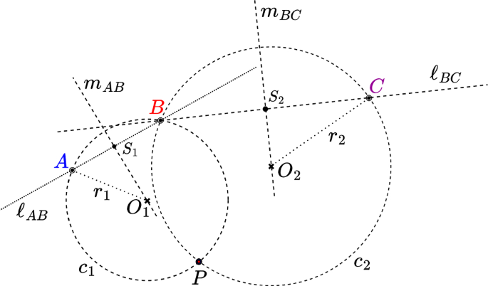
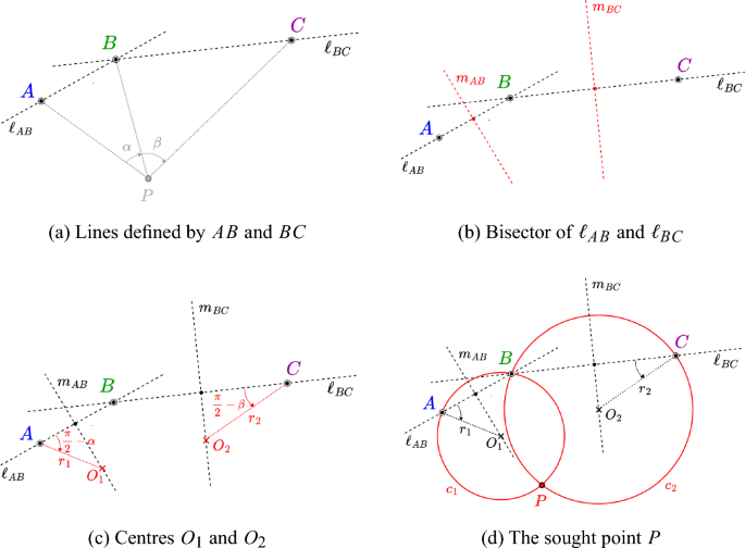
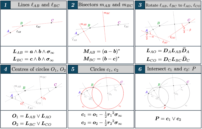
The Cassini method provides a solution to the resection problem by leveraging the inscribed angle theorem. The solution is obtained by determining the intersection of two circles: one passing through points A, B, and P, and the other through points B, C, and P as shown in Fig. 3. To determine the centres of the circles, two lines must be intersected. The step-by-step graphical approach underlying the Cassini method can be elucidated, along with the equivalent steps, using the CRA algebra (see Fig. 4).
-
1.
CRA Mapping: The problem starts by mapping three known Euclidean points, A, B, and C, to the CRA domain. For example, the point A with coordinates \((a_1,a_2)\) is mapped as
$$\begin{aligned} A=(a_1,a_2)&\longrightarrow \quad \vec {\varvec{a}}=a_1 \varvec{\sigma }_1 + a_2 \varvec{\sigma }_2 \nonumber \\&\longrightarrow \quad \varvec{{a}}=\varvec{\sigma }_0 + \vec {\varvec{a}} + \frac{1}{2}\vec {\varvec{a}}^2\varvec{\sigma }_{\infty } \end{aligned}$$(17) -
2.
Auxiliary Lines: To obtain the position of the centre of the circle defined by A, B, and P, the line \(\varvec{\ell }_{AB}\) joining A and B must first be constructed along with the line
 as the perpendicular bisector of \(\varvec{\ell }_{AB}\). The line \(\varvec{\ell }_{AO}\) is then constructed by rotating \(\varvec{\ell }_{AB}\) by \(({\pi }/{2}-\alpha )\) relative to A clockwise. This process is repeated for \(\varvec{\ell }_{BC}\) and
  but with \(\varvec{\ell }_{CO}\) being rotated some \(({\pi }/{2}-\beta )\) counterclockwise relative to C. $$\begin{aligned} \varvec{L}_{AB}&= \varvec{{a}} \wedge \varvec{{b}} \wedge \varvec{\sigma }_{\infty }, \quad \varvec{L}_{CB}= \varvec{{c}} \wedge \varvec{{b}} \wedge \varvec{\sigma }_{\infty } \nonumber \\ \varvec{M}_{AB}&=(\varvec{{a}}-\varvec{{b}})^{\star } \quad \varvec{M}_{BC} =(\varvec{{b}}-\varvec{{c}})^{\star } \end{aligned}$$(18)
For the rotated lines \(\varvec{\ell }_{AO_{1}}\) and \(\varvec{\ell }_{CO_{2}}\), the following rotors and translators must be first defined
$$\begin{aligned} \varvec{R}_{\alpha }&= e^{-\frac{1}{2}(\alpha - \pi /2)\varvec{\sigma }_{12}} , \quad \varvec{R}_{\beta } = e^{-\frac{1}{2} (\pi /2 - \beta )\varvec{\sigma }_{12}}\nonumber \\ \varvec{T}_{A}&= 1 - \frac{\vec {\varvec{a}}}{2}\varvec{\sigma }_\infty , \quad \varvec{T}_{C} = 1 - \frac{\vec {\varvec{c}}}{2} \varvec{\sigma }_\infty \nonumber \\ \varvec{D}_{A}&= \varvec{T}_A\varvec{R}_\alpha \widetilde{\varvec{T}}_A, \quad \varvec{D}_{C} = \varvec{T}_C\varvec{R}_\beta \widetilde{\varvec{T}}_C \end{aligned}$$(19), and thus,
$$\begin{aligned} \varvec{L}_{AO_{1}} = \varvec{D}_A\varvec{L}_{AB} \widetilde{\varvec{D}}_A, \quad \varvec{L}_{CO_{2}} = \varvec{D}_C\varvec{L}_{BC} \widetilde{\varvec{D}}_C \end{aligned}$$(20)Note that rotations are always relative to the origin. To rotate around an arbitrary point, it must first be translated to the origin. The rotation is then applied, followed by another translation that returns the point back to its original position.
-
3.
Circle building: The centres of the circles can now be found as the intersection of the lines \(\varvec{\ell }_{AB}\) and \(\varvec{\ell }_{AO_{1}}\) and \(\varvec{\ell }_{BC}\) and \(\varvec{\ell }_{CO_{2}}\)
$$\begin{aligned} \varvec{O}_1&=\varvec{o}_1 \wedge \varvec{\sigma }_\infty = \varvec{L}_{AB}\vee \varvec{L}_{AO}=(\varvec{L}_{AB} ^{\star } \wedge \varvec{L}_{AO}^{\star })^{\star }\nonumber \\ \varvec{O}_2&=\varvec{o}_2 \wedge \varvec{\sigma }_\infty = \varvec{L}_{BC}\vee \varvec{L}_{CO}=(\varvec{L}_{BC} ^{\star } \wedge \varvec{L}_{CO}^{\star })^{\star } \end{aligned}$$(21)The result is a flat point, representing the wedge of the sought point and the point at infinity.Footnote 1 The extraction of the point of interest is straightforward by factoring out the point at infinity
$$\begin{aligned}&\varvec{o}_1= ({\varvec{\sigma }}_{0} \cdot \varvec{O}_1- \varvec{\sigma }_{0})\nonumber \\&\varvec{o}_2= ({\varvec{\sigma }}_{0} \cdot \varvec{O}_2- \varvec{\sigma }_{0}) \end{aligned}$$(22)The radius of the circles can be computed as
$$\begin{aligned} r_1=\sqrt{-2(\varvec{o}_1\cdot \varvec{a})}, \qquad r_2=\sqrt{-2(\varvec{o}_2\cdot \varvec{c})} \end{aligned}$$(23), and the circles themselves are determined as
$$\begin{aligned} \varvec{c}_1=\left( \varvec{o}_1-\frac{1}{2}r_1^2\varvec{\sigma }_{\infty }\right) \qquad \varvec{c}_2=\left( \varvec{o}_2-\frac{1}{2}r_2^2\varvec{\sigma }_{\infty }\right) \end{aligned}$$(24) -
4.
Intersection of circles: The desired result can be obtained from the intersection of the two circles \(\varvec{c}_1\) and \(\varvec{c}_2\) as
$$\begin{aligned} \varvec{P}=\varvec{c}_1\wedge \varvec{c}_2 \end{aligned}$$(25)Two intersecting circles in CGA yield a couple of points (1D sphere), also known as pair-point \(\varvec{P}\). Finally, the Euclidean point P is recovered by the classic formula (see Hildenbrand 2018)
$$\begin{aligned} P_{\pm } = \frac{\pm \sqrt{\varvec{P}^{\star } \cdot \varvec{P}^{\star } } + \varvec{P}^{\star }}{\varvec{\sigma }_{\infty } \cdot \varvec{P}^{\star }} \end{aligned}$$(26)One of the points \( P_{\pm }\) is exactly the point B, and the other is the sought point P (see Fig. 3).
Figure 5 shows a concise and condensed summary of the key steps involved and discussed above. It provides valuable visual depictions that enhance the geometric intuition underlying the method, offering an algebraic interpretation of the graphical approach. It also helps to reinforce the strong connection between the graphical Cassini method and its algebraic translation using CRA.
The GitHub repository shows several examples derived from the code developed by the authors. The computational procedures in CGA are found to be straightforward. The methodology involves the manipulation and combination of geometric objects, thus justifying the occasional reference to GA as an object-oriented approach.
4.2.2 Collins construction
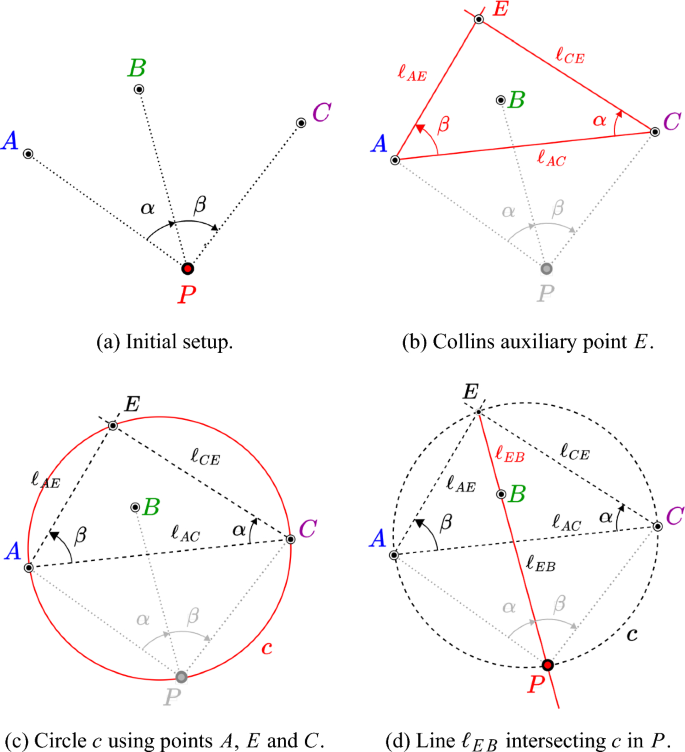
The graphical method of Collins provides a solution to the resection problem using the intersection of the line passing through the point B and the so-called Collins auxiliary point E with the circle containing the points A, C, and E. The step-by-step procedure for applying Collins’ method graphically is depicted in Fig. 6.
-
1.
CRA Mapping: Similarly to the Cassini method, the points A, B, and C must be mapped to CGA as
$$\begin{aligned} A=(a_1,a_2)&\longrightarrow \quad \vec {\varvec{a}}=a_1 \varvec{\sigma }_1 + a_2 \varvec{\sigma }_2 \nonumber \\&\longrightarrow \quad \varvec{{a}}=\varvec{\sigma }_0 + \vec {\varvec{a}} + \frac{1}{2}\vec {\varvec{a}}^2\varvec{\sigma }_{\infty } \end{aligned}$$(27) -
2.
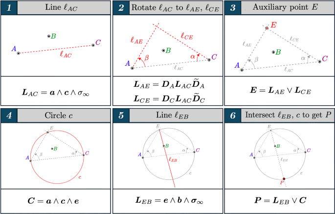
Auxiliary Point: To determine the auxiliary point E, it is necessary to define the lines \(\ell _{AE}\) and \(\ell _{CE}\) as shown in Fig. 6b by first rotating the line through A and C \((\ell _{AC})\) an angle \(\beta \) around the point A in a counterclockwise direction
$$\begin{aligned}&\varvec{L}_{AC} = \varvec{a} \wedge \varvec{c} \wedge \varvec{\sigma }_\infty \nonumber \\&\varvec{L}_{AE} = \varvec{D}_A \varvec{L}_{AC} \widetilde{\varvec{D}}_A \end{aligned}$$(28)and then rotate the line \(\ell _{AC}\) around C by an angle \(\alpha \) clockwise
$$\begin{aligned} \varvec{L}_{CE} = \varvec{D}_C \varvec{L}_{AC} \widetilde{\varvec{D}}_C \end{aligned}$$(29)with
$$\begin{aligned} \varvec{R}_\beta&= e^{-\frac{\beta }{2} \sigma _{12}}, \quad \varvec{R}_\alpha = e^{\frac{\alpha }{2} \sigma _{12}}\nonumber \\ \varvec{T}_A&= 1-\frac{\vec {\varvec{a}}}{2}\varvec{\sigma }_\infty , \quad \varvec{T}_C = 1-\frac{\vec {\varvec{c}}}{2}\varvec{\sigma }_\infty \nonumber \\ \varvec{D}_A&= \varvec{T}_A \varvec{R}_\beta \widetilde{\varvec{T}}_A, \quad \varvec{D}_C = \varvec{T}_C \varvec{R}_\alpha \widetilde{\varvec{T}}_C \end{aligned}$$(30)The intersection of the two lines determines the position of the Collins auxiliary point E
$$\begin{aligned} \varvec{E}&=\varvec{e} \wedge \varvec{\sigma }_\infty = \varvec{L}_{AE} \vee \varvec{L}_{CE} \nonumber \\&= (\varvec{L}_{AE}^{\star } \wedge \varvec{L}_{CE}^{\star })^{\star } \end{aligned}$$(31)We get the Collins point as a flat point and use the standard projection to receive E.
-
3.
Circle and Line intersection: Using the points A, C, and E, the circle c that passes through them is built
$$\begin{aligned} \varvec{C} = \varvec{a} \wedge \varvec{c} \wedge \varvec{e} \end{aligned}$$(32)The end point P we are looking for is found by intersecting the circle c and the line through E and B (see Fig. 6d),
$$\begin{aligned}&\varvec{L}_{EB} = \varvec{e} \wedge \varvec{b} \wedge \varvec{\sigma }_\infty \nonumber \\&\varvec{P} = \varvec{L}_{EB} \vee \varvec{C} = (\varvec{L}_{EB}^{\star } \wedge \varvec{C}^{\star })^{\star } \end{aligned}$$(33)The intersection of a line and a circle results in a pair-point \(\varvec{P}\). As in the previous method, Eq. (26) is used to extract the two distinct points, one of them being the point E and the other the sought point P.
Figure 7 shows a visual summary of the key steps of the Collins method.
4.3 Resection method in 3D
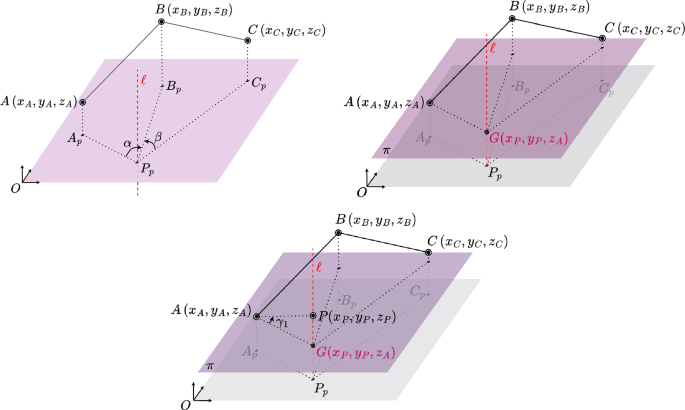
The construction procedure for the 3D case is carried out in a series of detailed steps, as in the 2D sections and as illustrated in Fig. 8. The main idea is to project all points into a plane parallel to the reference plane \(\varvec{\sigma }_{12}\) (the plane xy). It can be any, but we chose the one that passes through one of the known points (for example, point A). Then, we apply one of the methods presented in the previous sections to this simplified 2D version of the original problem, and finally, we solve for the \(\varvec{\sigma }_3\) (z) coordinate of the projected point. Section 5 provides specific examples.
-
1.
CRA Mapping: Represent Euclidean points \(A,B,C \in \mathbb R^3\) in VGA as vectors \(\vec {\varvec{x}}=x_1 \varvec{\sigma }_1 +x_2 \varvec{\sigma }_2 + x_3 \varvec{\sigma }_3\), project them into the xy plane (\(\varvec{\sigma }_1 \wedge \varvec{\sigma }_2 = \varvec{\sigma }_{12}\)) by formulas
$$\begin{aligned} \vec {\varvec{a}}_p&=\vec {\varvec{a}}-(\varvec{\sigma }_3 \cdot \vec {\varvec{a}}) \varvec{\sigma }_3 = (\vec {\varvec{a}}\cdot \varvec{\sigma }_{12}) \varvec{\sigma }_{21} \nonumber \\ \vec {\varvec{b}}_p&=\vec {\varvec{b}}-(\varvec{\sigma }_3 \cdot \vec {\varvec{b}}) \varvec{\sigma }_3 = (\vec {\varvec{b}}\cdot \varvec{\sigma }_{12}) \varvec{\sigma }_{21}\nonumber \\ \vec {\varvec{c}}_p&=\vec {\varvec{c}}-(\varvec{\sigma }_3 \cdot \vec {\varvec{c}}) \varvec{\sigma }_3 = (\vec {\varvec{c}}\cdot \varvec{\sigma }_{12})\varvec{\sigma }_{21} \end{aligned}$$(34)Note that, for computational purposes, it is sufficient to remove component \(x_3\) for this specific case. The points are now mapped to the CRA domain
$$\begin{aligned}&A_p \quad \longrightarrow \quad \vec {\varvec{a}}_p \quad \longrightarrow \quad \varvec{a}_p\nonumber \\&B_p\quad \longrightarrow \quad \vec {\varvec{b}}_p \quad \longrightarrow \quad \varvec{b}_p \nonumber \\&C_p \quad \longrightarrow \quad \vec {\varvec{c}}_p \quad \longrightarrow \quad \varvec{c}_p \end{aligned}$$(35) -
2.
2D Solution: Use one of the methods described in Sect. 4.2 to solve the problem restricted to the plane xy, obtaining the points \(P_1\) and \(P_2\). The choice point will be designated as \(P_p\) for subsequent steps.
-
3.
3D Reconstruction: Find the line \(\ell \) perpendicular to the xy plane that passes through the point \(P_p\)
$$\begin{aligned} \varvec{L}={\varvec{p}}_p \wedge \varvec{u}_3 \end{aligned}$$(36)where \(\varvec{u}_3=\varvec{\sigma }_3 \wedge \varvec{\sigma }_{\infty }\) is the CGA representation of a free vector in direction of \(\varvec{\sigma }_3\). Now, find the plane \(\varvec{\pi }_A\) perpendicular to the line \(\ell \) that passes through the point A
$$\begin{aligned} \varvec{\Pi }_A =(\varvec{a} \cdot \varvec{L})^{\star } \wedge \varvec{\sigma }_{\infty } \end{aligned}$$(37)The intersection of the line \(\ell \) and the plane \(\varvec{\pi }_A\) determines the point G (obtained as a flat point)
$$\begin{aligned} \varvec{G} = \varvec{\Pi }_A \vee \varvec{L} =(\varvec{\Pi }_A ^{\star } \wedge \varvec{L} ^{\star } )^{\star } \end{aligned}$$(38), and thus, the point at infinity must be removed using the standard formula, recovering the intersecting point G in CGA
$$\begin{aligned} \varvec{g}= ({\varvec{\sigma }}_{0} \cdot \varvec{G}- \varvec{\sigma }_{0}) \end{aligned}$$(39)Using the inverse map from CGA to VGA, we end up with \(\vec {\varvec{g}}\) and the point of interest \(\vec {\varvec{p}}\) (P) can be obtained as
$$\begin{aligned} \vec {\varvec{p}}=\vec {\varvec{g}}+\varvec{\sigma }_3\tan (\gamma _1) \sqrt{-2 (\varvec{g} \cdot \varvec{a})} \end{aligned}$$(40)To obtain the point P without performing the last trigonometric operation, the line AG can be rotated around A by the angle \(\gamma _1\) in the plane perpendicular to the plane xy containing the line AG.
4.4 Singularities of the methods
All three methods presented so far, i.e. VGA, Cassini CRA, and Collins CRA, encounter the same intrinsic limitation known as the dangerous circle. This issue is unavoidable with the Snellius–Pothenot formulation, where the unknown point P is part of the circle determined by the three known points. However, the graphical methods of Cassini and Collins offer distinct advantages over the VGA approach by avoiding the use of trigonometry, regardless of the challenges posed by singularities. This simplifies certain computational aspects and potentially enhances the geometric intuition behind the solutions, providing a more straightforward path to address the resection problem in specific scenarios.
For example, the angles \(\alpha \) and \(\beta \) in the denominators of Eq. (15) play a crucial role in the VGA method. If either angle is zero, then the result is infinity (meaning that point P lies on line segment AB or BC). This is a common issue in all traditional methods where some trigonometric formulation is used [see Pierlot and Van Droogenbroeck (2014) for details]. To mitigate this effect in the VGA method, different reference stations can be selected to avoid zero values for \(\alpha \) or \(\beta \).
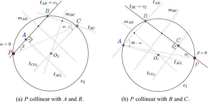
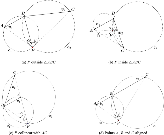
In contrast, the Cassini CRA method can elegantly solve this issue graphically. Moreover, the CRA formulation also manages to capture the simplicity of the geometric solution. Figure 9a shows the specific situation where the point P is collinear with AB (a similar case occurs for collinearity with BC, see Fig. 9b). In either case, one of the circles degenerates into a line, and the solution simply consists of intersecting this line with the remaining circle. This is a clear example of how to deal with the singularities inherent in the trigonometric formulation by leveraging the basic principles of planar geometry. This provides a more intuitive approach to handling special alignments compared to ad hoc fixes needed for traditional resection techniques. It should be noted that no singularity occurs if P is collinear with the segment AC.
Interestingly, the Collins method presents an additional singularity beyond that of the Cassini method, occurring when the point P is collinear with segment AC.
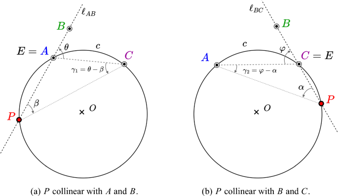
The singularity due to the alignment of P with the sides AB or BC is solved as shown in Fig. 10. Essentially, the point P is obtained from the intersection of the line passing through A and B and another line built by rotating line AC around C by an angle equal to \(\gamma _1=\theta -\beta \) (or rotating AC around A by \(\gamma _2=\varphi -\alpha \) if alignment occurs with BC). This elegant geometric construction circumvents the infinity values that arise in the trigonometric formulation when P aligns with any side of the triangle ABC. The Collins CRA approach thereby extends the advantages of the Cassini method to fully address all possible singular configurations through basic planar geometry principles.
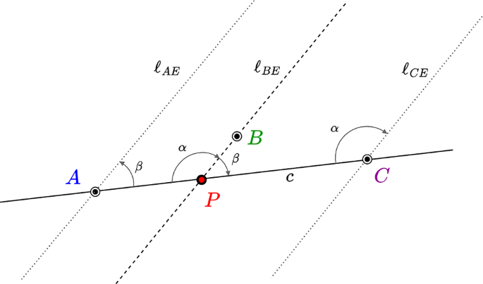
Finally, the singularity caused by the collinearity between P and AC is solved as follows. Note that in this situation, the rotated lines \(\ell _{AE}\) and \(\ell _{CE}\) are parallel as in Fig. 11. We can recognise this by the fact that the projection of the flat point (38) is not a point, but a direction at infinity.Footnote 2 However, the search line is then characterised by the point B and the directional vector \(\varvec{u}=(\varvec{\sigma }_4 \wedge \varvec{\sigma }_3) \cdot \varvec{L}_{AE}\), that is, \(\varvec{L}_{BE}=\varvec{b} \wedge \varvec{u} \wedge \varvec{\sigma }_{\infty }\). The point we are looking for is \(\varvec{P}= \varvec{L}_{BE} \vee \varvec{L}_{AC}\), which is a flat point originating from the wedge product of our sought point P and the point at infinity \(\varvec{P}=\varvec{p}\wedge \varvec{\sigma }_{\infty }\).
5 Numerical simulations and benchmarks
5.1 Two-dimensional example
Both the VGA and CGA approaches detailed in Sects. 4.1 and 4.2, respectively, have been implemented using specific GA software to address the 2D resection problem. Clifford (Hadfield et al. 2021) and GA-FuL (Eid [36]) packages were used to facilitate the work with GA. The algorithms we devised have been uploaded to GitHub, accessible via the following link: https://github.com/jorgeven98/Resection-Problem-3D. These algorithms were rigorously tested using various configurations, as illustrated in Fig. 12. The locations of the known points, as well as the angles \(\alpha \) and \(\beta \), can be retrieved from the code shared on GitHub in every instance. Remarkably, GA-based methods enable us to precisely solve any initial point arrangement.
In Table 3, numerical data regarding the positions of known points A, B, and C, as well as angles \(\alpha \) and \(\beta \), are presented for the four scenarios. To address these cases, the coordinates of all points (including the unknown point P) are initially established. An auxiliary mathematical function is then employed, in conjunction with these coordinates, to ascertain the angles with precision. Subsequently, this derived angular information, together with the locations of the known points, is incorporated into our computational algorithms. The primary objective is to confirm that the calculated results are consistent with the coordinates initially designated for the point P.
5.2 Three-dimensional example
To evaluate the newly developed 3D resolution method, several examples have been proposed and solved, each featuring a distinct configuration of 3D points (see Table 4). For the purpose of this study, we will focus on configuration a), while the remaining examples are analysed similarly.
In the first step, we convert points A, B, and C into VGA vectors
Assuming that the position of the unknown point \(\vec {\varvec{p}}\) is \((6.8103,-6.6307,14.5388)\), the values of the horizontal angles are \(\alpha =-39.7471^{\circ }\), \(\beta =305.0165^{\circ }\) and the vertical angle is \(\gamma _1=31.1521^{\circ }\). It should be noted that \(\alpha \) and \(\beta \) are the angles between points \(A_p\) and \(B_p\), and \(B_p\) and \(C_p\), respectively, as seen from \(P_p\). The subscript p indicates the projection of that point in the xy plane. On the other hand, \(\gamma _1\) is the angle through which A sees P measured in the plane perpendicular to the \(\varvec{\sigma }_3\) axis and taking as a reference the line parallel to the xy plane. In this case, the point A has been selected, but any other point could be used.
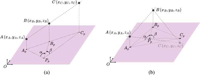
3D visualisation for configurations b) and c) in Table 4. a Points A, B, and C aligned. b The projections of A, B, and C in the plane xy form a triangle with P projected inside
The procedure proposed in Sect. 4.3 is followed. By projecting onto the xy plane and solving the 2D version of the problem, we obtain the following solution
The intermediate geometric objects are also computed, with the following results:
As a result, our desired point is \(P=(6.8103,-6.6307, 14.5388)\), matching the original position vector \(\vec {\varvec{p}}\).
Figure 13 shows the point configurations for examples b) and c) in Table 4. By applying the same method as in example a), we can determine the precise location of point P, regardless of the positions of points A, B, and C with no limitations, but the unsolvable forbidden circle (all points lying in the same plane and P belonging to the circle defined by points A, B, and C).
5.3 Benchmarks
To evaluate the computational efficiency of our GA-based algorithms, extensive benchmarking tests were performed and the results were compared with state-of-the-art methods. Our implementation, which exploits the power of code generation, has achieved superior performance, outperforming the best-known algorithms to date, such as the ToTal algorithm and the method proposed by Ligas. Moreover, sophisticated CGA-based approaches have shown excellent results and are among the most efficient in terms of execution time.
A comprehensive set of benchmarks was conducted, comparing our algorithms against top-efficient algorithms operating in the whole plane and accommodating any ordering for the known points. Each algorithm was executed \(10^6\) times at random locations within the same square-shaped area used for error analysis (see next section). The tests were performed on an Intel Core i7-9700K CPU 3.60GHz (Coffee Lake) with 8 logical and 8 physical cores (8 GB RAM, Windows 11, C#,.NET SDK 8.0.102).
Our findings reveal that our VGA-based algorithm outperforms state-of-the-art methods (see Table 5), executing approximately 13.3% and 30% faster than the previously best-known algorithms by Pierlot with Total #1 and Total #2.
The primary advantage of our methodology and implementation is the utilisation of GA-FuL’s comprehensive code generation capabilities. These capabilities range from generating code for individual multivector operations to creating full software libraries with proper software architecture and nested folder/file structure, enabling efficient and optimised geometric algebra computations.
6 Uncertainty analysis
This section investigates the impact of measurement uncertainties on the efficacy of the proposed GA methods. Given the intrinsic presence of noise in practical measurements, it is crucial to assess the sensitivity and resilience of the method to such perturbations (Font-Llagunes and Batlle 2009a; Pierlot and Van Droogenbroeck 2014).
Previous discussions have highlighted that the resection problem faces an intractable challenge within the forbidden circle defined by points A, B, and C. This limitation is inherent in the nature of the problem rather than a reflection of the methods used to solve it. Novel methodological approaches should be considered with caution as they may inadvertently introduce undesirable scenarios and singularities not covered by the original formulation of the problem. In this regard, the proposed methods handle degenerate or limiting cases in a convenient and elegant graphical way, as shown in Fig. 11.
This study presents three approaches to address the problem of 2D and 3D resection. In order to improve the ability to evaluate the accuracy of the algorithms and determine the station position error, a new metric has been developed. Consequently, we propose three formulations that are essentially different variations of the same underlying approach, each defining the metric D based on the square of a distance to denote the proximity of the station P to the forbidden region.
-
VGA method: The vector \(\varvec{d}\) is used as the difference between the vectors \(\varvec{d}_1\) and \(\varvec{d}_2\) (refer to Eq. (15)). When the station P is located on the forbidden circle, the vectors \(\varvec{d}_1\) and \(\varvec{d}_2\) converge, resulting in a null vector \(\varvec{d}\). Therefore, minimal values of D indicate close proximity to the forbidden circle
$$\begin{aligned} D=\varvec{d}^2 \end{aligned}$$(41) -
Cassini method: The determination of D using the CGA Cassini method requires the calculation of the squared distance between the centres of the circles \({c_1}\) and \({c_2}\) (as shown in Fig. 4), marked by \(O_1\) and \(O_2\), respectively. In situations where the station is positioned on the forbidden circle, the two circles converge, causing their centres to overlap and the intercentre distance to become 0. Thus, according to Eq. (A3), D is defined as
$$\begin{aligned} D = -2(\varvec{o_1} \cdot \varvec{o_2}) \end{aligned}$$(42) -
Collins method: Similarly to the previous method, D is determined as the squared distance between two specific points. The auxiliary Collins point E and the point B are used for this purpose. They coincide when the station P is situated on the forbidden circle. The formula used to compute this distance is as follows
$$\begin{aligned} D = -2(\varvec{e} \cdot \varvec{b}) \end{aligned}$$(43)
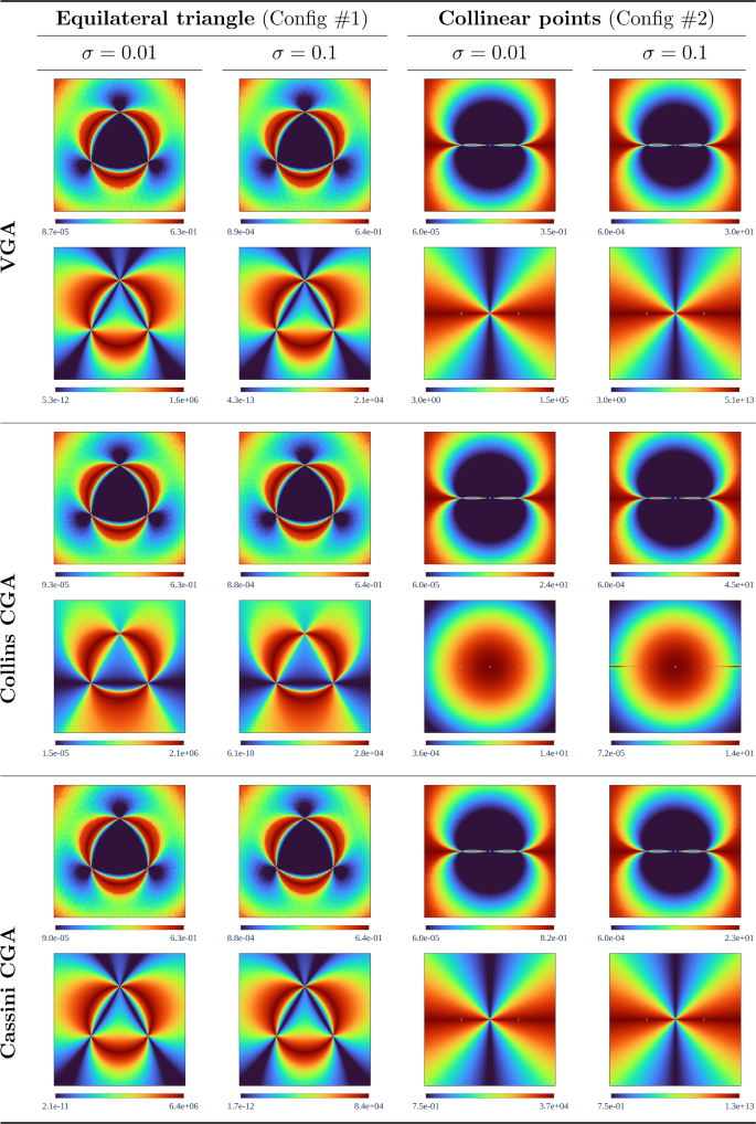
Error analysis for two point configurations using a square window of \(2\times 2\) m.. Config #1 is an equilateral triangle, while in config #2 the points are collinear. Both configurations have been tested with standard deviation \(\sigma =0.01\) and \(\sigma =0.1\). The three GA methods (VGA, CollinsCGA, and CassiniCGA) are compared based on their position error (first row) and metric 1/D (second row), respectively
To validate the sensitivity of the proposed algorithms, a series of simulations have been proposed. The simulation framework is designed within a square area measuring 4 by 4 square metres, incorporating two unique configurations for three known points. The first configuration is an equilateral triangle, with the points located at the positions \(A = (0,1)\), \(B = (-0.866, -0.5)\), and \(C = (0.866, -0.5)\). The points in the second configuration are linearly arranged at \(A = (-0.866,0)\), \(B = (0, 0)\), and \(C = (0.866, 0)\). A spacing of 2 cm is used in each direction across the grid. At each point on the grid, the angles \(\alpha \) and \(\beta \) seen from P are calculated. Gaussian noise is introduced into these angles, characterised by a zero mean and two distinct standard deviations (\(\sigma \) = 0.01 degrees and \(\sigma \) = 0.1 degrees). The algorithms use these modified angles as input to determine the estimated position of the unknown point. The discrepancy in position (\(\Delta d\)) is quantified by the Euclidean distance between the exact and estimated location of the point P.
The study performs 1000 iterations for each position to determine the standard deviation of the position error. The resulting standard deviations are shown in Fig. 14. The results for the equilateral triangle configuration, with standard deviations of \(\sigma \) = 0.01 degrees and \(\sigma \) = 0.1 degrees, are presented in the first and second columns, respectively. Similarly, the results for the second configuration (collinear points) are detailed in the third and fourth columns, respectively, using the same standard deviations. The figure shows the standard deviation of the position error and the mean error measure 1/D in the first and second rows, in that order. It is important to note that the scales used in the graphic representation are not linear. To enhance the visual clarity of these images and emphasise the correlation between the position errors and our new error metric, we applied histogram equalisation to the images.
6.1 Discussion of the results
The simulations performed are in agreement with those reported in the literature and support the case studies of each of the three methods presented. Figure 14 shows the different point configurations, where the forbidden circle is clearly identifiable due to the increase in standard deviation of the position error as it is approached. Minimal errors are observed inside the circle, while errors increase with distance outside the circle. It is remarkable that the three methods provide almost identical results for the error position.
The 1/D metric plots maintain a shape similar to the position error plots near the forbidden circle. High red values are observed as D becomes smaller, while minimum values are observed in the lines \(\ell _{AB}\) and \(\ell _{BC}\) in Cassini and \(\ell _{AC}\) in Collins due to an increase of D (see Figs. 9 and 10).
Configuration 2 transforms the forbidden circle into a straight line. In this region, the error distribution is high and increases progressively with distance from the line. Because this configuration represents a degenerate situation, the case where D becomes zero does not occur. The different methods used to define D lead to overlapping points at infinity, causing D to take high values near the critical line and resulting in a minimal value for 1/D. The metric D was chosen for configuration 2 due to this property.
All methods produce identical position error plots, indicating consistency and conformity with the results obtained by most algorithms to solve the resection problem. This confirms that the sensitivity to calculate the position of the point P, even with noisy measured angles, is independent of the method used and unique, as discussed in Pierlot and Van Droogenbroeck (2014) and Font-Llagunes and Batlle (2009b). The metric 1/D can be used as an indicator of proximity to the forbidden circle. When dealing with aligned beacons, the value of D should be used directly. In other cases, the similarity between this metric and the position error suggests that the former can approximate the latter if a function of the other problem parameters is applied.
7 Conclusions
This article presents a novel approach to solving the resection problem in two and three dimensions using conformal geometric algebra (CGA). The CGA framework allowed representing points, lines, planes, circles, and spheres in a unified mathematical structure and offered a more intuitive understanding and efficient solution to the resection problem compared to existing algebraic techniques.
The proposed method leveraged the ability of CGA to transition between different reference frames without requiring coordinate transformations. This eliminated the need for multiple calculation steps and complex algebraic manipulations that are characteristic of traditional algebraic solutions. Through extensive numerical simulations, we have demonstrated the validity and efficacy of our GA-based approach, achieving accuracy comparable to that of established algebraic techniques, while significantly improving computational efficiency and providing valuable geometric insights.
Our findings suggest that the geometric algebra framework has strong potential for solving resection-type problems not only in surveying and geodesy but also in computer graphics, robotics, computer vision, and navigation. By exploiting geometric relationships between entities, CGA paves the way for more intuitive solutions that unify computations involving different geometric primitives.
Future research can build upon the ideas presented here to address more complex variants of the resection problem that involve additional constraints. The CGA method can also be extended to address intersection problems and other spatial geometric computations across diverse disciplines. By harnessing the power of geometric algebra and the versatility of conformal geometric methods, this work opens up new possibilities for advancing geometric research and computational techniques.
Notes
A line can be considered as a circle with infinite radius, so the intersection of two lines results in two points, one at infinity.
A more simple argument is that \(\alpha +\beta =k\pi \) with \(k=0,1,...\)
References
Awange JL, Grafarend EW (2005) Solving algebraic computational problems in geodesy and geoinformatics. Algebraic computational problems in geodesy and geoinformatics
Awange JL (2002) Groebner basis solution of planar resection. Surv Rev 36(283):528–543
Awange JL, Grafarend EW (2002) Sylvester resultant solution of planar ranging problem. Allgemeine Vermessungs-Nachrichten 108(4):143–146
Awange J, Grafarend EW (2003a) Groebner-basis solution of the three-dimensional resection problem (p4p). J Geodesy 77:327–337
Awange JL, Grafarend EW (2003b) Multipolynomial resultant solution of the three-dimensional resection problem (p4p). Bollettino di Geodesia e Science affini 62(2):79–102
Awange JL, Grafarend EW, Paláncz B, Zaletnyik P (2010) Algebraic geodesy and geoinformatics. Springer, Berlin
Bähr H (1991) Einfach überbestimmtes ebenes einschneiden, differentialgeometrisch analysiert. Zeitschrift für Vermessungswesen 116(1991):545–552
Bil P (1992) Sectie en projectie. Nederlands Geodetisch Tijdschrift Geodesia
Bock W (1956) Mathematische und geschichtliche betrachtungen zum einschneiden. Ph.D. thesis, Institute f. Geodäsie u. Photogrammetrie d. Technischen Hochschule
Cameron J, Lasenby J (2008) Oriented conformal geometric algebra. Adv Appl Clifford Algebras 18:523–538
Dekov D (2012) A numerical method for solving the horizontal resection problem in surveying. J Geodetic Sci 2(1):65–67
Dorst L, Fontijne D, Mann S (2010) Geometric algebra for computer science: an object-oriented approach to geometry. Elsevier, Burlington
Eid AH Geometric Algebra Fulcrum Library (GA-FuL). https://github.com/ga-explorer/GeometricAlgebraFulcrumLib. Accessed 2024
Fischler MA, Bolles RC (1981) Random sample consensus: a paradigm for model fitting with applications to image analysis and automated cartography. Commun ACM 24(6):381–395
Font-Llagunes JM, Batlle JA (2009a) Consistent triangulation for mobile robot localization using discontinuous angular measurements. Robot Auton Syst 57(9):931–942
Font-Llagunes JM, Batlle JA (2009b) New method that solves the three-point resection problem using straight lines intersection. J Surv Eng 135(2):39–45
Grunert JA (1841) Das pothenot’sche problem, in erweiterter gestalt nebst bemerkungen über seine anwendung in der geodäsie". Archiv der Mathematik und Physik 1:238–248
Hadfield H, Wieser E, Arsenovic A, Kern R (2021) The Pygae Team: Pygae/clifford. https://doi.org/10.5281/zenodo.1453978
Hestenes D, Sobczyk G (2012) Clifford algebra to geometric calculus: a unified language for mathematics and physics, vol 5. Springer, Dordrecht
Hildenbrand D (2018) Introduction to geometric algebra computing, 1st edn. Chapman and Hall/CRC, Boca Raton
Hitzer E, Lavor C, Hildenbrand D (2022) Current survey of clifford geometric algebra applications. Math Methods Appl Sci
Hrdina J, Návrat A (2017) Binocular computer vision based on conformal geometric algebra. Adv Appl Clifford Algebras 27:1945–1959
Hrdina J, Návrat A, Vašík P, Matoušek R (2017) CGA-based robotic snake control. Adv Appl Clifford Algebras 27:621–632
Hrdina J, Návrat A, Vašík P, Dorst L (2021) Projective geometric algebra as a subalgebra of conformal geometric algebra. Adv Appl Clifford Algebras 31:1–14
Masselli A, Zell A (2014) A new geometric approach for faster solving the perspective-three-point problem. In: 2014 22nd international conference on pattern recognition, pp 2119–2124. IEEE
Mazaheri M, Habib A (2015) Quaternion-based solutions for the single photo resection problem. Photogramm Eng Remote Sens 81(3):209–217
McCaw GT (1918) Resection in survey. Geograph J 52(2):105–123
Montoya FG, Baños R, Alcayde A, Arrabal-Campos FM (2019) Analysis of power flow under non-sinusoidal conditions in the presence of harmonics and interharmonics using geometric algebra. Int J Electr Power Energy Syst 111:486–492
Montoya FG, Baños R, Alcayde A, Arrabal-Campos FM, Roldán-Pérez J (2021) Vector geometric algebra in power systems: An updated formulation of apparent power under non-sinusoidal conditions. Mathematics 9(11):1295
Paláncz B, Awange JL, Zaletnyik P, Lewis RH (2010) Linear homotopy solution of nonlinear systems of equations in geodesy. J Geodesy 84:79–95
Pereira FI, Luft JA, Ilha G, Susin A (2018) A novel resection-intersection algorithm with fast triangulation applied to monocular visual odometry. IEEE Trans Intell Transp Syst 19(11):3584–3593
Pierlot V, Van Droogenbroeck M (2014) A new three object triangulation algorithm for mobile robot positioning. IEEE Trans Robot 30(3):566–577
Selig JM (2005) Geometric fundamentals of robotics, 2nd edn. Monographs in computer science. Springer, New York. https://doi.org/10.1007/b138859
Smith J (2023a) Solving the Snellius-Pothenot resection (surveying) problem via geometric algebra. https://www.youtube.com/watch?v=h863AAQ3lF8. Accessed 9 April 2023
Smith J (2023b) Via geometric algebra: a solution to the Snellius-Pothenot resection (surveying) problem. arXiv:2305.0079
Sturmfels B (2002) Solving systems of polynomial equations, vol 97. American Mathematical Society, Berkeley
Wareham R, Cameron J, Lasenby J (2004) Applications of conformal geometric algebra in computer vision and graphics. In: International workshop on mathematics mechanization, pp 329–349. Springer, Berlin
Wreede LC (2007) Willebrord Snellius (1580–1626): a Humanist Reshaping the Mathematical Sciences. Utrecht University, Utrecht
Zaplana I, Hadfield H, Lasenby J (2022) Closed-form solutions for the inverse kinematics of serial robots using conformal geometric algebra. Mech Mach Theory 173:104835
Funding
Funding for open access publishing: Universidad de Almería/CBUA.
Author information
Authors and Affiliations
Corresponding author
Appendix A Some calculations over CGA
Appendix A Some calculations over CGA
CGA has been briefly introduced in Sect. 2.2. In this Appendix, some fundamental calculations are presented to illustrate the computational efficiency inherent in this algebra. For further information and a detailed understanding, the reader is referred to Hrdina et al. (2021), Dorst et al. (2010), Hestenes and Sobczyk (2012), Hildenbrand (2018).
1.1 A.1 Conformal inclusion
We’ll show how the translations and rotations are connected and related to the insertion of the Euclidean space. If we choose vector \(\varvec{\sigma }_0\) as the origin of the coordinate system and use the element
, then it can act as a translation, allowing us to define an inclusion as a translation of the origin \(\varvec{\sigma }_0\) in the direction of the vector \(\vec {\varvec{x}}=(x \varvec{\sigma }_1 + y \varvec{\sigma }_2 +z \varvec{\sigma }_3)\) by the sandwich product as
So, we see that we can identify points in \(\mathbb R^3\) with vectors in CGA through the inclusion
where the element \(\varvec{T}\) acts as a translation. Using a similar reasoning, the element \(\varvec{R}=e^{n_1\varvec{\sigma }_2\varvec{\sigma }_3 +n_2\varvec{\sigma }_1\varvec{\sigma }_3+n_3\varvec{\sigma }_1\varvec{\sigma }_2}\) acts as a rotation due to identification \(\text {Im } {\mathbb {H}} =\langle \varvec{\sigma }_2\varvec{\sigma }_3,\varvec{\sigma }_1\varvec{\sigma }_3, \varvec{\sigma }_1\varvec{\sigma }_2 \rangle \) and the following computation
1.2 A.2 Distance between points
One of the key distinctions between CGA and VGA lies in the interpretation of the inner product. In CGA, the inner product represents the distance between points, which is fundamentally a quadratic concept in VGA. By incorporating two additional dimensions, CGA linearises this quadratic function. The equation below elucidates this:
This calculation explicitly demonstrates how CGA linearises the quadratic nature of the distance representation found in VGA, offering nuanced insights into geometric relations and interactions between points.
Furthermore, this characteristic is utilised to depict the midline \(\varvec{M}_{}\) as illustrated in expression (18). A midline is established by two control points, \(\varvec{a}\) and \(\varvec{b}\), and encompasses points that maintain equal distances to these control points. This means that \( (\varvec{x}-\varvec{a})^2 = (\varvec{x}-\varvec{b})^2 \). In the context of CGA, this condition can be articulated as follows:
i.e. \(\varvec{x} \in \varvec{M}_{AB} \leftrightarrow \varvec{x} \cdot (\varvec{a} -\varvec{b}) =0\), so \((\varvec{a} - \varvec{b})\) is the IPNS representation of the midline defined by control points \(\varvec{a}\) and \(\varvec{b}\).
1.3 A.3 IPNS vs OPNS representation of objects
In GA, we have several types of product, so it is possible to represent objects in different ways. With the help of the inner product, we can define the object \({\mathcal {C}}\) as follows.
In CGA, for example, the object \({\mathcal {C}} = n_1 \varvec{\sigma }_1+n_2 \varvec{\sigma }_2 +n_3 \varvec{\sigma }_3 + d \varvec{\sigma }_{\infty }\) can be tested and verify that it represents a plane
where \(\vec {\varvec{n}} = n_1 \varvec{\sigma }_1+n_2 \varvec{\sigma }_2+n_3 \varvec{\sigma }_3\). Equation (A5) describes a plane with normal vector \(\vec {\varvec{n}}\) and distance from the origin d. On the other hand, the wedge product defines an object \({\mathcal {D}}\) as follows
Again, in CGA, for example, the object
defines the line goes through the points \(\varvec{a}\) and \(\varvec{b}\):
So
which represented the line based on the points \(\varvec{a}\) and \(\varvec{b}\).
Rights and permissions
Open Access This article is licensed under a Creative Commons Attribution 4.0 International License, which permits use, sharing, adaptation, distribution and reproduction in any medium or format, as long as you give appropriate credit to the original author(s) and the source, provide a link to the Creative Commons licence, and indicate if changes were made. The images or other third party material in this article are included in the article’s Creative Commons licence, unless indicated otherwise in a credit line to the material. If material is not included in the article’s Creative Commons licence and your intended use is not permitted by statutory regulation or exceeds the permitted use, you will need to obtain permission directly from the copyright holder. To view a copy of this licence, visit http://creativecommons.org/licenses/by/4.0/.
About this article
Cite this article
Ventura, J., Martinez, F., Manzano-Agugliaro, F. et al. A novel geometric method based on conformal geometric algebra applied to the resection problem in two and three dimensions. J Geod 98, 47 (2024). https://doi.org/10.1007/s00190-024-01854-1
Received:
Accepted:
Published:
DOI: https://doi.org/10.1007/s00190-024-01854-1




 as the perpendicular bisector of
  but with