
Abstract
The market share of thermally modified wood (TMW) has increased in Europe during the past few years as an environmentally friendly and durable building product. However, TMW products of today are not permitted for use in structural applications, because the reduction in strength that is caused by thermal treatment cannot be accounted for. The purpose of this paper was to investigate the bending properties of thermally modified timber (TMT) of Norway spruce, and to explore possibilities to predict the bending properties of TMT. A sample of 100 boards from a 2X-log sawing pattern of 100 logs was thermally modified according to the ThermoWood® process, while the mirror 100 boards served as an unmodified control sample. Two non-destructive methods were employed: (1) a novel method based on scanning of fibre directions to obtain the lowest edgewise bending modulus of elasticity (MOE) along a board, and (2) a conventional excitation method to determine the first axial resonance frequency used to calculate the axial dynamic MOE. Finally, the boards were bent to failure according to European standard EN 408. Despite the fact that bending strength was reduced by 42% due to thermal treatment, the type and location of failure in TMT remained related to the presence of knots. Prediction of bending strength based on local fibre direction and axial dynamic MOE gave coefficients of determination of 0.51 for the thermally modified boards and 0.69 for the control boards, whereas axial dynamic MOE alone gave 0.46 and 0.57, respectively. These results indicate that although Norway spruce TMT has lower bending strength compared to unmodified timber, predictions of the bending strength can be made with good accuracy.
1 Introduction
In the last few decades thermally modified wood (TMW) has been commercialised and spread throughout Europe. The technology provides a sustainable alternative to tropical hardwood and preservative treated wood, and the total production of TMW was approx. 280,000 m3 in 2010 (Militz and Altgen 2014) and 300,000 m3 in 2015 (Altgen 2016). However, current TMW products are limited to non-structural applications, since the loss in strength and the increased brittleness that are attributable to thermal treatment cannot be accounted for (Stamm et al. 1946; Kubojima et al. 2000; Arnold 2010; Widmann et al. 2012). Whereas strength diminishes when wood is exposed to heat, it was shown that dimensional stability and resistance against decay increase significantly (Stamm et al. 1946; Rowell et al. 2009; Metsä-Kortelainen et al. 2011). During thermal treatment, the cell wall material is chemically deteriorated to a certain extent, which results in a permanent change of the material properties. The deterioration includes a loss in hemicelluloses, and since this component is highly hydrophobic, this loss in mass is one of the main explanations for the decrease in equilibrium moisture content (EMC) and increase in dimensional stability and durability of TMW (Mahnert et al. 2013; Rowell et al. 2013; Altgen 2016). It is also assumed that the decrease in strength is largely related to this loss in mass (Windeisen et al. 2009; Rowell et al. 2013; Winandy and Rowell 2013). Another reason that limits the use of TMW products to non-structural applications is that there is insufficient available data to establish relationships between various strength properties. Furthermore, the current European standard on strength grading of structural timber (EN 14081-1 2016) does not include the influence of process factors, whereas the effect of thermal treatment on the mechanical properties of TMW is process-dependent.
In thermal modification methods that are commercially available today, temperatures between 160 and 240 °C are used, the exclusion of oxygen is aimed for, and each have distinctive process conditions. After treatment, the material properties will depend on wood species and process conditions, the latter being controlled by a number of key factors, i.e. temperature, duration, initial moisture content, and oxygen level (Militz and Altgen 2014). Besides industrial processes, there are a vast number of treatment methods that have been performed on a laboratory scale (e.g. MacLean 1954; Mitchell 1988; Kubojima et al. 2000). These studies often aimed at evaluating the influence of process conditions on mechanical properties. Kubojima et al. (2000) studied the stress–strain curve in static bending and force–time curve in impact bending of Sitka spruce modified at 160 °C with durations from 0.5 to 16 h in an enclosed environment with nitrogen or air. In general, mean values of static and dynamic modulus of elasticity in bending, bending strength (also known as modulus of rupture) and absorbed energy in impact bending increased, compared to untreated wood, for short treatment durations, but decreased for longer durations. The presence of oxygen led to a higher decrease for all the investigated entities. As concluded earlier by MacLean (1954), the static bending properties were affected in ascending order: modulus of elasticity (MOE), modulus of rupture (MOR) and work to maximum load (WML). Similar differences in MOE and MOR between unmodified and TMW were reported by others, such as Metsä-Kortelainen and Viitanen (2010) and Rautkari et al. (2014).
The rate of change in properties of thermally modified products depends mainly on the treatment temperature and time (Winandy and Rowell 2013). For example, a loss in MOR was noticeable after heating Sitka spruce in the absence of air for 5 h at 160 °C or for 10 min at 210 °C (Stamm et al. 1946; Kubojima et al. 2000). The mechanical properties of TMW are not only determined by treatment temperature, duration and level of oxygen, but also by the relative humidity (RH) in the heating atmosphere. TMW modified at low RH was more brittle than TMW modified at a higher RH, which could be attributed to realignments of the amorphous polymers in the cell wall’s ultra-structure that reduced plastic deformations (Borrega and Kärenlampi 2008; Hughes et al. 2015; Altgen and Militz 2016). Furthermore, the resistance against decay fungi is enhanced with increasing treatment temperatures. To achieve sufficient decay resistance, temperatures above 200–220 °C for 3 h are required (Jämsä and Viitaniemi 2001; Syrjänen 2001; Metsä-Kortelainen and Viitanen 2010), which as a consequence, can lead to a loss in MOR as high as 50% (Bekhta and Niemz 2003).
The ThermoWood® process is the most common industrial thermal modification method in Europe (Altgen 2016). In this method, superheated steam at atmospheric pressure is used to transfer heat to the wood and to shield off oxygen (Hill 2006; Militz and Altgen 2014). Although it is common practice to modify spruce and pine at target temperatures of 180 °C (Thermo-S) and 212 °C (Thermo-D), several hardwood species can also be modified (International ThermoWood Association 2003, 2016). Thermo-D softwood is mainly used in cladding and decking as well as in furniture products that are exposed to wet conditions, which can be either indoors (e.g. saunas and kitchens) or outdoors. Mechanical properties of small clear wood samples of spruce modified using the ThermoWood® process have been reported in the literature by for example Frühwald (2007) and Metsä-Kortelainen and Viitanen (2010). However, since the number of specimens in these studies was small, the data therein can only be considered as indicative for mechanical properties of spruce ThermoWood®.
For more than 1250 clear wood samples of Norway spruce, coefficients of determination (R2) describing the relationships between MOR and MOE in bending, MOR and density, and MOE and density were found as high as 0.76, 0.66 and 0.64, respectively (Foslie 1971). Although wood density is not always a strong indicator of strength and stiffness properties, wood having a relatively low density is expected to have a relatively low MOR and MOE in bending as well (Johansson 2003). However, the decrease in density due to thermal treatment does not correspond to the change in MOR of modified clear wood. In addition, the levels of MOE as well as the MOE-density relationship remained similar to unmodified clear wood, whereas density decreased due to thermal treatment (Frühwald 2007; Arnold 2009, 2010). This illustrates that the effect of treatment on MOR and MOE cannot be explained, or at least not directly, by the mass loss that resulted from thermal treatment, and therefore has to be related to changes in the cell wall chemistry. For this reason, many studies have investigated the relationship between changes in wood chemistry and mechanical properties of TMW (Tjeerdsma et al. 1998; Boonstra et al. 2007b; Windeisen et al. 2009; Winandy and Rowell 2013), but no clear relationships have been presented yet.
Although it has been shown that thermal treatment affects mechanical properties of clear wood to varying degrees, only few studies have focussed on the strength assessment of thermally modified timber (TMT). As a result of thermal modification (max. 220°C/5 h, duration 5 days), the mean static edgewise bending strength (fm) of spruce and pine timber decreased as much as 50% compared with unmodified timber, whereas changes in static bending MOE were non-significant (Bengtsson et al. 2002). In addition, correlations between fm and bending MOE of TMT were weaker than those for unmodified timber, but the former correlations illustrated that possibilities for strength predictions do exist. At the same time, the bending strength of beech TMT was more difficult to estimate due to the low coefficients of determination between fm and static and dynamic MOE, respectively (Widmann and Beikircher 2010). Smaller reductions in bending strength of timber can be expected at lower treatment temperatures than those used in thermal modification. For example, high-temperature drying of Norway spruce timber at 115 °C and 120 °C resulted in 9.5 and 11.5% lower fm, respectively, compared to conventional kiln-drying (75 °C) while density (ρ) and static MOE remained unaffected (Bengtsson and Betzold 2000). Moreover, according to that investigation, the relationships in terms of coefficients of determination between fm-MOE, fm-ρ and ρ-MOE were not changed compared to the corresponding relationships between properties for conventional kiln-drying timber.
Previous results illustrate that TMT has a potential for use in constructions (Bengtsson et al. 2002; Boonstra et al. 2007a; Widmann et al. 2012), and the industry shows interest in the use of such products for structures exposed to loading. However, such application requires a more thorough understanding of the level and variation of the strength that remains after thermal modification. In particular in the construction sector, it is important for many practical applications that reliable predictions of mechanical properties of timber are made.
In this paper, the bending behaviour of spruce TMT was investigated with the purpose to get a clear insight into its strength properties and to explore possibilities for predicting the bending properties of TMT. By means of careful material selection, it was aimed at better analysing the influence of the thermal modification process on basic bending properties of timber. In addition, high-resolution fibre scanning, a technique that has shown high yields in grading of structural timber (Olsson et al. 2013), was employed to study not only the location of failure in TMT but also possibilities to improve bending strength predictions of TMT. Axial dynamic excitation, a conventional technique used in today’s machine strength grading, was also used and served for comparisons. The results could provide better insights into bending strength properties of TMT that are needed for expanding its uses.
2 Material
The material used in this study consisted of 200 Norway spruce (Picea abies L. Karst) boards with cross-sectional dimensions of 45 × 145 mm2 (t × h) and 3.6 to 4.8 m in length (L). Boards were sawn with a 2X-log pattern from 100 logs with a minimum diameter of 200 mm harvested in the inlands north of Karlstad, central Sweden. After sawing, the boards were dried to 12% moisture content and then planed. The sawing, drying and planing was carried out at Stora Enso’s sawmill in Gruvön located close to Karlstad. One of the boards taken from each log, i.e. a total of 100 boards, was thermally modified (TM) according to the ThermoWood® process in an industrial batch to meet class Thermo-D. The process has a maximum temperature of 212 °C for 3 h with a total treatment time of 3 days (International ThermoWood Association 2003). The thermal modification was performed at Stora Enso’s treatment facility in Launkalne, Latvia. The remaining 100 mirror boards served as a control sample to evaluate the effect of thermal treatment on the static edgewise bending strength (fm) and bending behaviour of the boards, and relationships between boards’ properties and fm. An overview of the preparation of control and TM boards is given in Fig. 1.

Preparation of control and TM boards
3 Methods
3.1 Non-destructive tests and calculation of indicating properties
3.1.1 Density
The air-dry density (ρ) calculated as board’s mass divided by board’s volume was determined prior to thermal treatment for the 100 control and the 100 unmodified TM boards. After thermal modification, ρ was determined again for the 100 TM boards. The air-dry condition was reached after storing the boards in the laboratory hall (approx. 20 °C and 60% RH).
3.1.2 Axial dynamic excitation
Prior to thermal treatment, a standard longitudinal vibration method was employed to determine the first axial resonance frequency (fa,1) for the 100 control and the 100 unmodified TM boards. The details of this free-free vibration method involving tapping by a small hammer, detection of the tap tone by a microphone and identification of the resonance frequencies by a fast Fourier analyser can be found in Olsson et al. (2012). On the basis of the obtained data, the axial dynamic MOE (Ea,1) of each board was established as:
The excitation method was repeated after thermal modification to determine Ea,1 for the 100 TM boards.
3.1.3 Scanning of fibre direction
A WoodEye 5 high-resolution laser scanner (WoodEye AB, Linköping, Sweden) was used to obtain the fibre direction on the boards’ surfaces prior to thermal treatment for the 100 control and the 100 unmodified TM boards. Based on the scanning of fibre directions, a local bending MOE profile was calculated. A description of a method developed for this purpose by Olsson et al. (2013), and how it was implemented in the present study, is described as follows:
-
(a)
The in-plane fibre direction on the surfaces of each board from end-to-end was obtained from laser scanning (Fig. 2a, b). The out-of-plane fibre angle (e.g. described in Simonaho et al. 2004) was ignored. The obtained resolution of fibre direction data was 3.6 mm in transverse and 0.8 mm in longitudinal direction of the board
-
(b)
The in-plane angle of the fibre direction (φ) represented a small area on the board’s surface as shown in Fig. 2a. The φ of such an area was assumed valid to a certain depth into the board
-
(c)
A local MOE, Ex(x, y, z) that is effective in the longitudinal board direction x was calculated for every position within the board’s volume, and was based on φ and a set of nominal material parameters. To define these nominal values, nine independent material parameters (3 moduli of elasticity, 3 shear moduli and 3 Poisson’s ratios) that describe the material of Norway spruce wood were obtained from Dinwoodie (2000)
-
(d)
The edgewise bending stiffness for each position x was calculated by integration over the cross-sectional area of a board slice with length dx illustrated in Fig. 2a, as:
$$E{I_{\text{z}}}\left( x \right)=~\iint {E_{\text{x}}}{\left( {y - \bar {y}} \right)^2}dzdy$$(2)where:
$$\bar {y}=~\frac{{\iint {E_{\text{x}}}ydzdy}}{{\iint {E_{\text{x}}}dzdy}}$$(3)Fig. 2 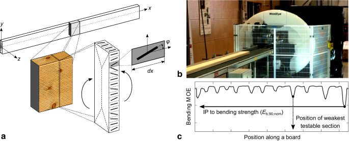
Graphical illustration of the high-resolution scanning of fibre direction technique. a Local fibre directions scanned on a board’s surface by means of a row of laser dots with a segment length dx for which the edgewise bending MOE is calculated by integration over the board’s cross section, b WoodEye-scanner, and c a bending MOE profile obtained by considering all the segments of the board
-
(e)
A high-resolution bending MOE profile Eb(x) along the length of the board was calculated as:
$${E_{\text{b}}}\left( x \right)=~\frac{{E{I_{\text{z}}}\left( x \right)}}{{\frac{1}{{12}}t{h^3}}}$$(4)Figure 2c shows a bending MOE profile that was obtained by calculating a moving average of Eb(x) over a length of 90 mm, i.e. Eb,90(x). The lowest bending MOE along this profile is assigned as Eb,90,nom. The subscript nom refers to the assigned nominal material parameters.

The application of laser scanning on TMT was not a scope of this study, and therefore scanning of fibre direction of TM boards was not included.
3.2 Static bending test
The 100 control and the 100 TM boards were tested in a four-point bending test following EN 408 (2012) to determine the static edgewise bending strength (fm), and the local- (Em,l) and global (Em,g) moduli of elasticity. The expected weakest section that could be positioned between the load points was identified using the bending MOE profile as shown in Fig. 2c. Global deflection (w) was measured in the board’s neutral axis at mid-span over a total span of 2,610 mm (18 h); local deflection (v) was recorded on the tension side between the load points over a length of 725 mm (5 h). The tension side was selected randomly, but it was made sure that each pair of boards was oriented in the same way (i.e. shared knots in the control and TM board cut from the same log were always positioned either in tension or compression). The test machine ALWETRON TCT 100 (Lorentzen & Wettre AB, Stockholm, Sweden) was used, which has a 100 kN load cell and applies load by pulling the specimen upwards. Two lateral supports were installed on the outside of each loading point to prevent lateral torsional buckling. The test was performed deformation controlled after 150 N preloading, followed by a constant load speed of 5 mm/min until 0.50 mm local deflection, and then continued at 15 mm/min up to failure. During testing, failure at maximum load (Fmax), the position of failure and time to failure were recorded. Preliminary failures, i.e. failures that occurred before reaching Fmax, were identified by jumps in the load–deflection curve. Moisture content (MC) and oven-dry density (ρOD) of each board were determined directly after testing following EN 13183-1 (2002). Bending properties and density were not adjusted to a MC of 12%, because the established conversions to this MC level are not valid for TMT. In addition, bending strength values were not adjusted to a board height of 150 mm, since this correction would be negligible. The shear modulus was set to infinity when calculating Em,g according to the expression given in EN 408 (2012).
3.3 Statistical analysis
The prediction of bending strength (response variable) of spruce TMT based on various non-destructive properties (predictor variables) was established through simple and multiple linear regression. In connection with strength grading of timber, the predictor variable is often referred to as indicating property (IP). When several predictor variables are involved, the IP is defined by a (linear) combination of these variables. In this paper, the IPs that correspond to variables and their combinations, which were determined (1) before and (2) after thermal modification were: (1) board density (ρ), axial dynamic MOE (Ea,1) and lowest local bending MOE (Eb,90,nom), and (2) board density (ρ), axial dynamic MOE (Ea,1), global static MOE (Em,g) and local static MOE (Em,l).
A key output of the regression analysis is the coefficient of determination (denoted by R2). It is interpreted as, for example, the proportion of the variance in bending strength that is predictable from a certain IP. Here, use was made of the adjusted R2. Descriptive statistics were also computed and included standard error of estimate (SEE), sample’s mean, standard deviation (std) and coefficient of variation (CoV). The statistical significance of differences between mean values and standard deviations of the control and TM boards were based on a two-sample t-test and two-sample F-test, respectively. The F-test was also used to determine the statistical significance of regression models. All statistics were calculated using the software Matlab®.
4 Results and discussion
4.1 Board properties
Table 1 shows mean values, standard deviations and CoVs for measured properties of the 100 control and 100 TM boards, respectively. The mean values of MC, ρ and ρOD were significantly lower after thermal treatment, whereas their standard deviations were statistically equivalent. The mean value of MC at the time of testing was 12.9% for the control and 4.6% for the TM boards. This difference in MC is in line with expectations for unmodified and ThermoWood-D spruce that is conditioned at a relative humidity of 60% (International ThermoWood Association 2003). Depending on the process conditions, TMW experiences an MC of 12% in air (20 °C) that is nearly saturated (International ThermoWood Association 2003; Arnold 2010). It is therefore of little practical importance to compare the control and TM boards at similar levels of MC (e.g. a level of 12% MC as prescribed in EN 408 (2012)). Nevertheless, it is important to note that strength and stiffness properties of TM small clear wood specimens loaded in bending were found lower for increasing levels of MC, but the influence of MC on these properties was smaller compared to unmodified reference samples (Arnold 2010). It should also be kept in mind that the effect of MC on properties was determined on small clear wood specimens. For (unmodified) structural timber, it is known that the decrease in bending properties with increasing MC depends on timber quality (Green et al. 1999). The mean value of ρ was 9% lower for TM boards compared to control boards. Comparing the mean ρOD of both samples, a 6% loss in dry density can be attributed to the treatment process. In fact, the loss in wood substance as a result of thermal modification was higher, since the cross-sectional area that was also reduced by the treatment process was used to calculate ρOD. The time to failure was on average 230 s for control boards and 163 s for TM boards. For a proper interpretation of the results, it should be noted that cross-sectional dimensions of each board at the time of destructive testing were taken into account when calculating their stiffness and strength properties. In addition, the mean values and standard deviations of properties that were determined non-destructively prior to thermal treatment (i.e. ρ and Ea,1) were statistically equivalent between the control and unmodified TM boards (data not included in this paper). Therefore, follow-up comparisons between the two sample sets should give a good indication of the effect of thermal treatment on the mechanical properties of timber.
The local moduli of elasticity in bending (Em,l) in Table 1 were within a similar range for the control and the TM boards, and mean values and CoVs were 12.7 GPa and 17%, respectively, for both samples. The mean values of Em,l of the spruce boards obtained in this investigation are comparable with results achieved in other investigations on spruce that was grown in Sweden (Bengtsson and Betzold 2000; Bengtsson et al. 2002; Ranta-Maunus and Denzler 2009; Olsson and Oscarsson 2017). In a two-sample t-test and F-test, no significant differences were found when different MOEs (Ea,l, Em,g and Em,l) were compared between control and TM boards (Table 1). The mean MOEs and their standard deviation of the control and TM boards were therefore statistically equivalent as was confirmed earlier for mean values of static MOEs (Bengtsson et al. 2002; Widmann et al. 2012). In addition, the relationship between the static bending MOEs remained valid after thermal treatment as stated by Widmann et al. (2012), and the ratios found herein are in line with previous results from research in which MOEs of unmodified and TMT of spruce have been compared (Bengtsson et al. 2002). In detail, the mean Em,l was higher than the mean Em,g with a ratio (Em,l/Em,g) of 1.11 and 1.13 for the control and TM boards, respectively. Moreover, the ratios between static and dynamic MOE were within the same range as what has been reported for unmodified spruce (Ravenshorst and Van de Kuilen 2009; Olsson et al. 2012).
Table 1 shows significant differences between mean values and standard deviations of control and TM boards for bending strength (fm) and work to maximum load (WML) in static bending. A mean bending strength of 45 MPa with a CoV of 26% was found for the control boards, which is typical for Norway spruce timber coming from the Nordic countries (Johansson 2003; Olsson and Oscarsson 2017). The mean bending strength of the TM boards was 26 MPa, which is 42% lower than the value for control boards, whereas the CoV was increased to 34%. This decrease in bending strength was less compared to findings by Bengtsson et al. (2002), which is most likely caused by the lower treatment intensity (duration and temperature) in the present research. A similar increase in the coefficient of variation due to thermal treatment has been reported before, for both clear wood and timber, and for both softwoods and hardwoods (Bengtsson et al. 2002; Arnold 2009; Widmann et al. 2012).
4.2 Bending behaviour
4.2.1 Bending strength
The bending strength values of control and TM boards are depicted in a cumulative frequency diagram in Fig. 3. The data in this figure show that the increase in CoV after treatment is related to the decrease in mean strength and not to an increase in the standard deviation of bending strength, which was significantly lower for TM boards (Table 1). The bending strength of the control boards was spread over a range of 54 MPa between 16.2 and 69.9 MPa whereas that of the TM boards was spread over a range of 41 MPa between 8.7 and 49.4 MPa. The lines in Fig. 3 indicate the mean and characteristic strength of each sample set. The latter is the lower fifth percentile bending strength (fm,k). The characteristic strength for the control boards was 23.9 MPa, and the corresponding value for the TM boards was 11.7 MPa, respectively. That is a reduction of 51% due to thermal modification. This more pronounced decrease in the characteristic values compared to mean values was observed in previous research concerning both high-temperature dried timber (Bengtsson and Betzold 2000) and thermally modified timber (Bengtsson et al. 2002; Widmann et al. 2012). At the same time, Fig. 3 also illustrates that the absolute difference in bending strength between the control and TM boards (ΔCTM) was larger for timber with a higher bending strength. Since the bending strength of timber is mainly determined by the presence of knots (Johansson 2003), higher quality timber is characterised by fewer and smaller knots. Under the assumption that the presence of knots is also governing the bending strength of TMT, the findings based on Fig. 3 suggest that knot-free wood is affected more in terms of MPa by thermal treatment compared to wood containing knots. This fact was reported earlier for chemically treated wood (Winandy and Rowell 2013). However, it is evident that further studies regarding the relationship between the presence of knots and strength of TMT are required before more certain conclusions could be drawn.

Cumulative frequency diagram of bending strength (fm) of control (non-filled circles) and TM (filled circles) boards, and their absolute difference (ΔCTM). Note that fm,mean and fm,k denotes the mean and characteristic bending strength of each sample set, respectively
4.2.2 Load–deflection curves
Figure 4a shows examples of load–deflection (F–w) curves obtained from the bending tests of 4 board pairs. The figure illustrates the global deflection (w) versus force (F) until point of maximum loading (Fmax). The maximum deflection (i.e. deflection at Fmax) was lower for TM boards. The control boards failed at a deflection of 24–93 mm, whereas TM boards failed after deflections of 11–40 mm. Based on F–w curves of the 100 control and the 100 TM boards, four different types of curves could be distinguished: (1) sudden failure, (2) preliminary failure prior to failure at Fmax, (3) non-linearity prior to failure at Fmax, and (4) preliminary failures and non-linearity prior to failure at Fmax. Figure 4b illustrates these four types and shows how many boards in each sample set behaved according to each curve type. A number of control boards showed non-linearity in the F–w curve. The TM boards, however, failed either suddenly, i.e. according to curve type 1 (38% of the TM boards), or after some preliminary failures, i.e. according to curve type 2 (62% of the TM boards). The area under the F–w curve must have been reduced by 66% due to thermal modification, given that: (1) both the control and the TM boards behaved linear elastically up to failure, (2) thermal treatment does not change the slope of the F–w curve (which is shown in Table 1 by the unaltered MOE after modification), and (3) that bending strength (fm) of TM boards was reduced by 42% (Table 1).

a Examples of F–w curves of 4 board pairs (i.e. the boards in each pair originate from the same log). Note that an offset of 20 mm is used on the x-axis to avoid overlapping. b Classification of F–w curves including the frequency of occurrence per curve type for control and TM boards, respectively: (1) sudden failure, (2) preliminary failure prior to failure, (3) non-linearity prior to failure, and (4) preliminary failures and non-linearity prior to failure
4.2.3 Ductility
The area below the F–w curve measures the combined influence of force and deflection. This area describes the amount of elastic energy that is stored in the board prior to failure. When this is divided by the loaded wood volume it is known as work or energy to maximum load (WML) (Dinwoodie 2000). Similar to impact bending, WML is a measure of the toughness of a material, and already early studies on thermally modified wood showed that this mechanical property is the one affected the most by heat treatment (Stamm et al. 1946; MacLean 1954). A material with a high WML could be described as ductile whereas a material with a low WML as brittle. In this study, a WML mean value of 0.0075 mmN/mm3 was found for the TM boards versus 0.0267 mmN/mm3 for the control boards (Table 1), which is a difference of 72%. This decrease in WML was expected based on the earlier conclusion regarding the effect of thermal modification on the area below the F–w curve. A somewhat higher reduction in WML after treatment of 72% is explained by the fact that a number of the control boards experienced some non-linearity in the F–w curve prior to failure. It should be noted that the percentage difference in mean WML between the control and TM boards was larger compared to the percentage difference in mean bending strength. The cumulative frequency diagram in Fig. 5 clearly illustrates the difference in WML between the control and TM boards, which increases with timber quality (i.e. for less brittle timber). Again, it can be observed that the ductility of higher quality timber is affected more by thermal treatment. Since ductility is reduced over the full range of boards (i.e. for both low and high quality timber), TMT can be described as being more brittle compared to unmodified timber as concluded in previous studies (Kubojima et al. 2000; Arnold 2010; Widmann et al. 2012). However, it should be kept in mind that brittle failure occurs in unmodified timber as well (see Figs. 4, 5).

Cumulative frequency diagram of WML for control and TM boards
4.2.4 Bending failure
In the bending tests, five failure modes that correspond to failure modes for clear wood presented in ASTM D143-94 (2000) were observed: (1) simple tension, (2) cross-grain tension, (3) splintering tension, (4) compression and (5) horizontal shear failure. These five failure modes are illustrated in Fig. 6a–j. The figure also shows the frequency of occurrence of each failure type in percentage both for control and TM boards. In this study, a subdivision was made for types of simple tension failure (Fig. 6a–d) and cross-grain tension failure (Fig. 6e–g). Failure at Fmax was attributable to tension failure for all boards with one exception of a TM board that failed due to horizontal shear. Most boards failed due to simple tension failure. In general, simple tension failure occurred more often for TM boards (81% versus 67% for the control boards), whereas cross-grain tension and splintering tension were more common for the control boards (33% versus 18% for the TM boards). A similar amount of boards in both samples failed either in simple tension type 1 or 2. An example of simple tension failure of type 1 is shown in Fig. 7 for one control and one TM board.

Types of failure in bending test (side view) including the frequency of occurrence in percentage of control and TM boards. Note that the top side of the boards was loaded in tension and the bottom side in compression

Example of simple tension failure type 1 of a control and b TM board
The detail depicted in Fig. 7 shows the fractured surface on the board’s tension side and the fracture that developed around the knot. The majority of TM boards showed a brash fracture surface (65%) and the fracture was more often through knots (59%), whereas the control boards primarily experienced a fibrous fracture surface (68%) and the fracture was generally around knots (87%). Combined fractures through and around a knot (see e.g. detail b in Fig. 7) were recorded as fractures through a knot since this appeared to be the prominent type of failure.
4.2.5 Location of failure
The low values along the bending MOE profiles (e.g. shown in Fig. 2c) for the 100 control and the 100 unmodified TM boards corresponded well to positions of knots in a board, i.e. at positions where the angle of the fibre direction deviates from the board’s longitudinal direction (Olsson et al. 2013). Table 2 shows how often the location of failure in control and TM boards was predicted by scanning of fibre direction. Sixty-five percent (65%) of the TM boards and 64% of the control boards failed at the expected position. An example of a bending MOE profile where the location of failure was predicted successfully is illustrated in Fig. 8a. Table 2 also shows that about one-third of the boards in both sample sets failed at other sections than the predicted ones. Failure in these cases was usually located at another low value along the bending MOE profile (see e.g. Fig. 8b). Other reasons could be reaction wood (see e.g. Fig. 8c), cross-grain or horizontal shear failure. The results point out that the location of failure in TMT was related to the presence of knots about as often as it is for unmodified timber (Johansson et al. 1998). In detail, failure was reported in the vicinity of knots in 94% of the control boards and in 91% of the TM boards.

Predicted location of failure along the board based on scanning of fibre direction versus bending test. Examples for three TM boards when failure occurs at a the expected location, b at an unexpected location due to another low point of the MOE profile, and c at reaction wood
4.3 Prediction of bending strength
4.3.1 Simple linear regression
The coefficients of determination (R2) for predicting the bending properties from various IPs and combinations of IPs are presented in Table 3. For the control boards, Table 3 shows R2-values in the range of 0.53 to 0.63 for the relationship between fm and various MOEs. This is in line with earlier studies on Norway spruce timber where R2-values for these relationships typically range between 0.5 and 0.7 (Steffen et al. 1997; Johansson 2003). Looking at the same relationships in Table 3 for TM boards, R2-values ranged from 0.35 to 0.57. The decrease in coefficient of determination for TM boards was observed for every relationship between bending strength and the studied IPs. This finding is supported by an earlier examination of the relationships between bending strength, and local static MOE and dry density of thermally modified timber of spruce and pine (Bengtsson et al. 2002).
The relationships between bending strength and Em,g, Em,l, ρ and Ea,1 are shown in the scatterplots in Fig. 9a–d. In addition to the coefficient of determination (R2), equations for the regression lines and standard errors of estimate (SEE) are also given in the figure. Although higher R2-values were found for unmodified timber, the SEEs of the TM boards were somewhat lower compared to the control boards. This implies that the difference between the predicted bending strength values (fm-predicted) and the observed values (fm-test) was smaller for the TM boards.

Relationship between fm and, aEm,g, bEm,l, cρ, and dEa,1 for control (non-filled circles) and TM (filled circles) boards
For the relationship between fm and Em,l, Bengtsson et al. (2002) reported R2-values of 0.66 and 0.41 for unmodified and TMT of spruce, respectively. For the two sample sets investigated in the present study, the corresponding R2-values were 0.61 and 0.49, respectively, see Table 3 and Fig. 9b. Although the R2-values of unmodified timber were similar in the work by Bengtsson et al. (2002) and the work presented herein, the higher R2 that was found for the TM boards is most likely explained by the lower intensity of the modification process that was applied in this study. This indicates that the prediction of bending strength by means of MOE is more difficult for higher treatment intensities (duration and temperature). This was also concluded for beech and spruce clear wood that was modified at 180 and 220 °C (Arnold 2010).
Despite the fact that density is known to be a good predictor of clear wood bending strength (Foslie 1971), it is in general a poor predictor of timber bending strength, and R2-values between 0.16 and 0.40 can be expected (Hoffmeyer and Pedersen 1995). Not surprisingly, in this study rather low coefficients of determination of 0.20 and 0.17 were found for the unmodified and TM boards, respectively (see Table 3; Fig. 9c). The R2 of the ρ-fm relationship was lower for the TM boards compared to the control boards. Poor predictions of bending strength on a density basis have been reported previously for modified timber, but also for modified small clear wood samples (Bengtsson et al. 2002; Arnold 2009).
As shown in Table 3 and in Fig. 9d, the R2 between fm and Ea,1 was 0.46 for the TM boards and 0.57 for the control boards. Although the predictive power of Ea,1 was affected by thermal treatment, it had no influence whether Ea,1 was determined on the unmodified TM boards (i.e. before modification) or the modified TM boards (i.e. after modification), and corresponding R2-values were 0.47 and 0.46, respectively (Table 3). Referring to previous observations, this could be expected, since the MOEs were not affected by thermal treatment. Currently, the sawmilling industry in Europe uses Ea,1 as a technique to estimate the strength of structural timber (Olsson et al. 2013), and coefficients of determination of about 0.45–0.60 are generally achieved for spruce timber (Hanhijärvi and Ranta-Maunus 2008). Based on the aforementioned, it is evident that Ea,1 is suitable to predict the bending strength of TMT of spruce, and Ea,1 can either be obtained before or after the thermal modification process. It is evident that these conclusions should be used with caution, especially for batches of timber (unmodified) with a weak relationship between Ea,1 and fm (i.e. with a low R2). The same applies to predicting the effect of thermal modification on the Ea,1-fm relationship of such timber batches. The fact that a previous study on TMT of beech showed a weak correlation between the bending strength and dynamic MOE is most likely explained by the therein included correlations between bending strength and static MOEs, which were also poor (Widmann and Beikircher 2010).
The bending MOE profile, Eb,90(x), accounts for local fibre deviations on board surfaces to calculate a board’s lowest bending MOE over a length of 90 mm. Since significant fibre deviations occur mainly around knots (Olsson et al. 2013), the lowest value of Eb,90(x) can be interpreted as a measure of the board’s severest knot or knot cluster. It has been shown (Johansson 2003) that measurements of knots to calculate an effective cross-sectional area in combination with MOE can improve predictions of bending strength. Consequently, the method provided by Olsson et al. (2013) shows high yields for strength grading of structural timber with coefficients of determination of approximately 0.7. The local bending MOE proved to be less powerful in estimating the bending strength of unmodified and TM boards of spruce when only nominal material parameters are used to calculate Eb,90,nom, and R2-values of 0.53 and 0.35 were found for control and TM boards, respectively. The difference in R2 between the control and TM boards for the fm-Eb,90,nom relationship is 0.18, which is the largest difference found in this study compared to the R2 of the other IPs included. This finding might indicate that measures of knots or grain deviation are less effective for predictions of the bending strength of TMT compared to unmodified timber.
Whereas ρ decreased on average by 9% due to thermal treatment, it had little consequence whether the ρ was determined before or after treatment when employed as predictor of bending strength of the TM boards (Table 3). In addition, coefficients of determination for ρ-MOE relationships and relationships between MOEs shown in Table 3 were rather similar for the control and TM boards. For these reasons, it is thought that the ρ-fm and MOE-fm relationships changed due to the bending strength’s reduced standard deviation and the increased brittleness after thermal modification.
4.3.2 Multiple linear regression
Table 3 also shows the coefficients of determination when combining ρ, Ea,1 and Eb,90,nom with respect to fm in multiple linear regression. Ea,1 combined with Eb,90,nom is, as anticipated, a good predictor of bending strength of the control boards having an R2 of 0.69. Not surprisingly, coefficients of determination in Table 3 were lower for the TM boards. However, high-resolution fibre scanning combined with dynamic excitation shows good potential for predicting the bending strength of spruce TMT with a quite strong R2 of 0.51 using Ea,1 and Eb,90,nom. When combining Ea,1 and Eb,90,nom, a new indicating property (IP) to predict bending strength can be defined as (Ea,1 and Eb,90,nom in GPa):
and as:
for control and TM boards, respectively.
4.3.3 Grading example
Figure 10 shows the relationship between the IPs defined in Eqs. 5 and 6, and the bending strength of the control and TM boards, respectively. In this figure, the principles of C-class grading were applied to the TM boards as a basis for discussion about the possibilities of strength grading of TMT. This should be considered as a simplified example since grading according to EN 14081-2 (2018) involves more steps. The setting value SC14 for IPTM in this example was 8.0 GPa. After rejecting 11 boards, 89 boards of TMT could be assigned to strength class C14 with a characteristic bending strength of 14 MPa (EN 338 2016). The other grade determining properties, i.e. mean modulus of elasticity parallel to the grain and the characteristic density are, respectively, 12.4 GPa and 360 kg/m3 and were assessed following EN 384 (2016) and EN 408 (2012). In a similar manner, it was possible to grade 91 boards of unmodified timber to strength class C30. It should be clear that the previous example does not imply that this batch of TMT could be used as C14 structural timber. For a potential structural application, additional mechanical properties to the ones considered in this study should be evaluated. In addition, relationships between various strength properties of TMT should be further investigated since these may differ considerably compared to those of unmodified timber, as was pointed out before (Widmann and Beikircher 2010; Widmann et al. 2012). As a final remark, since the effect of TM on the mechanical properties of timber is process-dependent, factory production control (EN 14081-2 2018) might be a necessary complement to strength grading of TMT.

Relationship between fm and the IPs defined in Eqs. 5 and 6 for control (non-filled circles) and TM (filled circles) boards, respectively. Setting value SC14 based on IPTM defined in Eq. 6 when the TM boards would be graded to class C14. Note that analogously the control boards would be graded to class C30
5 Conclusion
The aim of this paper was to achieve a better understanding of the effect of thermal modification on the bending behaviour of Norway spruce timber, and to investigate possibilities for predicting the bending strength (fm) of TMT. Although the mean fm and WML decreased by 42% and 72%, respectively, because of thermal treatment, the standard deviations of these properties did not increase but were significantly lower for TMT. As was the case for unmodified timber, the type and location of failure in TMT were related to knots. The coefficients of determination between fm and the various moduli of elasticity confirmed that bending strength of TMT is more difficult to predict than what bending strength of unmodified timber is. However, the SEEs of these relationships were lower for TMT compared to unmodified timber. Nevertheless, predictions can still be made employing dynamic excitation, a technique that is currently used by the sawmilling industry for estimating the strength of structural timber. More accurate estimations of bending strength are, however, obtained by applying a novel technique based on high-resolution scanning of fibre directions on timber surfaces. In detail, this technique combined with dynamic excitation showed good potential for predicting fm of spruce TMT with a quite strong coefficient of determination of 0.51 with Eb,90,nom and Ea,1 as predictor variables. Since MOEs remained unaffected by thermal treatment, it is thought that MOE-fm relationships are affected by the reduced standard deviation of fm and the increased brittleness that were both attributable to thermal treatment. For this reason, it would be interesting to further investigate the bending behaviour of TMT especially at point of failure. Finally, possibilities to improve the application of high-resolution fibre scanning on TMT should be investigated, specifically by: (1) studying the effect of fibre angle on bending strength, (2) optimising the edgewise bending MOE of the weakest section based on fibre direction (Eb,90,nom), and (3) detection of fibre direction on the modified wood surface.
Abbreviations
- ρ :
-
Board’s air-dry density
- ρ OD :
-
Oven-dry density of a board’s section
- E b,90,nom :
-
Lowest edgewise bending MOE as moving average over a board length of 90 mm and based on the fibre direction on a board’s surface and nominal material parameters
- E a,1 :
-
Dynamic MOE based on a board’s first axial resonance frequency and ρ
- f m :
-
Static edgewise bending strength
- E m,l :
-
MOE based on local deflections in static bending
- E m,g :
-
MOE based on global deflections in static bending
- WML:
-
Work to maximum load in static bending
References
Altgen M (2016) Impact of process conditions in open and closed reactor systems on the properties of thermally modified wood. PhD thesis, Georg-August-Universität Göttingen, Cuvillier Verlag, Göttingen, Germany
Altgen M, Militz H (2016) Influence of process conditions on hygroscopicity and mechanical properties of European beech thermally modified in a high-pressure reactor system. Holzforsch 70(10):971–979
Arnold M (2009) Density-property relationships in thermally modified wood. In: Proc. of the 4th European Conference on Wood Modification, Stockholm, Sweden, pp 187–190
Arnold M (2010) Effect of moisture on the bending properties of thermally modified beech and spruce. J Mater Sci 45:669–680
ASTM D143-94 (2000) Standard test methods for small clear specimens of timber. ASTM International, West Conshohocken
Bekhta P, Niemz P (2003) Effect of high temperature on the change in color, dimensional stability and mechanical properties of spruce wood. Holzforsch 57(5):539–546
Bengtsson C, Betzold D (2000) Bending strength and stiffness of Norway spruce timber—influence of high temperature drying. In: Stanzl-Tschegg SE, Reiterer A (eds) Proc. of the International Symposium on Wood Machining, Christian-Doppler-Laboratory for Fundamentals of Wood Machining, Vienna, Austria, pp 139–149
Bengtsson C, Jermer J, Brem F (2002) Bending strength of heat-treated spruce and pine timber. In: Proc. of the International Research Group on Wood Preservation, Document No. IRG/WP 02-40242, Cardiff, Wales
Boonstra MJ, Van Acker J, Kegel EV (2007a) Effect of a two-stage heat treatment process on the mechanical properties of full construction timber. Wood Mater Sci Eng 2:138–146
Boonstra MJ, Van Acker J, Tjeerdsma BF, Kegel EV (2007b) Strength properties of thermally modified softwoods and its relation to polymeric structural wood constituents. Ann For Sci 64(7):679–690 (Springer Verlag/EDP Sciences)
Borrega M, Kärenlampi PP (2008) Mechanical behaviour of heat-treated spruce (Picea abies) wood at constant moisture content and ambient humidity. Holz Roh- Werkst 66:63–69
Dinwoodie JM (2000) Timber: its nature and behaviour. Taylor and Francis, Abingdon
EN 13183-1 (2002) Moisture content of a piece of sawn timber—part 1: determination by oven dry method. European Committee for Standardization (CEN), Brussels
EN 14081-1 (2016) Timber structures—strength graded structural timber with rectangular cross section—part 1: general. European Committee for Standardization (CEN), Brussels
EN 14081-2 (2018) Timber structures—strength graded structural timber with rectangular cross section—part 2: machine grading; additional requirements for initial type testing. European Committee for Standardization (CEN), Brussels
EN 338 (2016) Structural timber—strength classes. European Committee for Standardization (CEN), Brussels
EN 384 (2016) Structural timber—determination of characteristic values of mechanical properties and density. European Committee for Standardization (CEN), Brussels
EN 408 (2012) Structural timber—structural timber and glued laminated timber—determination of some physical and mechanical properties. European Committee for Standardization (CEN), Brussels
Foslie M (1971) Strength properties of Norwegian spruce (Picea abies karst). Part 3—strength properties of small, clear specimen. Tech. Rep. 42, The Norwegian Institute of Wood Working and Wood Technology
Frühwald E (2007) Effect of high-temperature drying on properties of Norway spruce and larch. Holz Roh- Werkst 65:411–418
Green DW, Winandy JE, Kretschmann DE (1999) Mechanical properties of wood. In: Wood handbook—wood as an engineering material. U.S. Department of Agriculture, Forest Service, Forest Products Laboratory, Madison, pp 1–45
Hanhijärvi A, Ranta-Maunus A (2008) Development of strength grading of timber using combined measurement techniques. Report of the Combigrade-project—phase 2. VTT Publications 686
Hill CAS (2006) Wood modification: chemical, thermal and other processes. Wiley, West Sussex
Hoffmeyer P, Pedersen JG (1995) Evaluation of density and strength of Norway spruce wood by near infrared reflectance spectroscopy. Holz Roh-Werkst 53(3):165–170
Hughes M, Hill CAS, Pfriem A (2015) The toughness of hygrothermally modified wood—a review. Holzforsch 69(7):851–862
International ThermoWood Association (2003) ThermoWood Handbook. Helsinki, Finland
International ThermoWood Association (2016) ThermoWood® Production statistics 2016. Tech. Rep
Jämsä S, Viitaniemi P (2001) Heat treatment of wood—better durability without chemicals. In: Rapp AO (ed) Proc. of COST Action E22 Environmental optimisation of wood protection, Antibes, France, pp 19–24
Johansson C-J (2003) Grading of timber with respect to mechanical properties. In: Thelandersson S, Larsen HJ (eds) Timber engineering. Wiley, West Sussex
Johansson C-J, Boström L, Bräuner L, Hoffmeyer P, Holmquist C, Solli KH (1998) Laminations for glued laminated timber—establishment of strength classes for visual strength grades and machine settings for glulam laminations of Nordic origin. Tech. Rep. 38, SP Swedish National Testing and Research Institute
Kubojima Y, Okano T, Ohta M (2000) Bending strength and toughness of heat-treated wood. J Wood Sci 46:8–15
MacLean JD (1954) Effect of heat on the properties and serviceability of wood: experiments on thin wood specimens. Tech. Rep., U.S. Department of Agriculture, Forest Service, Forest Products Laboratory, Madison 5, Wisconsin
Mahnert K-C, Adamopoulos S, Koch G, Militz H (2013) Topochemistry of heat-treated and N-methylol melamine modified wood of Koto (Pterygota macrocarpa K. Schum.) and Limba (Terminalia superba Engl. et Diels). Holzforsch 67(2):137–146
Metsä-Kortelainen S, Viitanen H (2010) Effect of fungal exposure on the strength of thermally modified Norway spruce and Scots pine. Wood Mater Sci Eng 1:13–23
Metsä-Kortelainen S, Paajanen L, Viitanen H (2011) Durability of thermally modified Norway spruce and Scots pine in above-ground conditions. Wood Mater Sci Eng 6:163–169
Militz H, Altgen M (2014) Processes and properties of thermally modified wood manufactured in Europe. In: Deterioration and protection of sustainable biomaterials (vol 982, pp 269–285), ACS Symposium Series
Mitchell PH (1988) Irreversible property changes of small loblolly pine specimens heated in air, nitrogen, or oxygen. Wood Fiber Sci 20(3):320–335
Olsson A, Oscarsson J (2017) Strength grading on the bais of high resolution laser scanning and dynamic excitation: a full scale investigation of performance. Eur J Wood Prod 75(1):17–31
Olsson A, Oscarsson J, Johansson M, Källsner B (2012) Prediction of timber bending strength on basis of bending stiffness and material homogeneity assessed from dynamic excitation. Wood Sci Technol 46:667–683
Olsson A, Oscarsson J, Serrano E, Källsner B, Johansson M, Enquist B (2013) Prediction of timber bending strength and in-member cross-sectional stiffness variation on the basis of local wood fibre orientation. Eur J Wood Prod 71:319–333
Ranta-Maunus A, Denzler JK (2009) Variability of strength of European spruce. In: Proc. of the International Council for Research and Innovation in Building and Construction. Working Commission W18—Timber structures (CIB-W18), Dübendorf, Switzerland
Rautkari L, Honkanen J, Hill CAS, Ridly-Ellis D, Hughes M (2014) Mechanical and physical properties of thermally modified Scots pine wood in high pressure reactor under saturated steam at 120, 150, 180 °C. Eur J Wood Prod 72:33–41
Ravenshorst GJP, Van de Kuilen JWG (2009) Relationships between local, global and dynamic modulus of elasticity for soft- and hardwoods. In: Proc. of the International Council for Research and Innovation in Building and Construction. Working Commission W18—Timber structures (CIB-W18/42-10-1), Dübendorf, Switzerland
Rowell RM, Ibach RE, McSweeny J, Nilsson T (2009) Understanding decay resistance, dimensional stability and strength changes in heat treated and acetylated wood. In: Proc. of the 4th European Conference on Wood Modification, Stockholm, Sweden, pp 489–502
Rowell RM, Andersone I, Andersons B (2013) Heat treatment. In: Rowell RM (ed) Handbook of wood chemistry and wood composites. CRC Press LLC, Boca Raton, pp 511–536
Simonaho S-P, Palviainen J, Tolonen Y, Silvennoinen R (2004) Determination of wood grain direction from laser light scattering pattern. Opt Lasers Eng 41:95–103
Stamm AJ, Horace K, Burr K, Kline AA (1946) Staybwood… Heat-stabilized wood. Ind Eng Chem 38(6):630–634
Steffen A, Johansson C-J, Wormuth E-W (1997) Study of the relationship between flatwise and edgewise moduli of elasticity of sawn timber as a means to improve mechanical strength grading technology. Holz Roh- Werkst 55:245–253
Syrjänen T (2001) Production and classification of heat treated wood in Finland. In: Rapp AO (ed) Proc. of COST Action E22 Environmental optimisation of wood protection, Antibes, France, pp 9–17
Tjeerdsma BF, Boonstra M, Pizzi A, Tekely P, Militz H (1998) Characterisation of thermally modified wood: molecular reasons for wood performance improvement. Holz Roh- Werkst 56:149–153
Widmann R, Beikircher W (2010) Thermally modified beechwood as structural material: allocation to European strength-classes and relevant grading procedures. In: Proc. of 11th World Conference on Timber Engineering, Riva del Garda, Italy, pp 996–1003
Widmann R, Fernandez-Cabo JL, Steiger R (2012) Mechanical properties of thermally modified beech timber for structural purposes. Eur J Wood Prod 70:775–784
Winandy JE, Rowell RM (2013) Chemistry of wood strength. In: Rowell RM (ed) Handbook of wood chemistry and wood composites. CRC Press LLC, Boca Raton, pp 413–455
Windeisen E, Bächle H, Zimmer B, Wegener G (2009) Relations between chemical changes and mechanical properties of thermally treated wood. Holzforsch 63:773–778
Acknowledgements
This research received funding from the Formas project “New aspects on the strength behaviour of thermally modified wood towards structural applications” (grant no. 942-2015-722, coordinator Prof. S. Adamopoulos). The timber and thermal modification were provided by Stora Enso Timber AB, Sweden.
Author information
Authors and Affiliations
Corresponding author
Ethics declarations
Conflict of interest
On behalf of all authors, the corresponding author states that there is no conflict of interest.
Additional information
Publisher’s Note
Springer Nature remains neutral with regard to jurisdictional claims in published maps and institutional affiliations.
Rights and permissions
OpenAccess This article is distributed under the terms of the Creative Commons Attribution 4.0 International License (http://creativecommons.org/licenses/by/4.0/), which permits unrestricted use, distribution, and reproduction in any medium, provided you give appropriate credit to the original author(s) and the source, provide a link to the Creative Commons license, and indicate if changes were made.
About this article

Cite this article
van Blokland, J., Olsson, A., Oscarsson, J. et al. Prediction of bending strength of thermally modified timber using high-resolution scanning of fibre direction. Eur. J. Wood Prod. 77, 327–340 (2019). https://doi.org/10.1007/s00107-019-01388-w
Received:
Published:
Issue Date:
DOI: https://doi.org/10.1007/s00107-019-01388-w