
Abstract
Some of the pavements in Seville Cathedral still display full-scale geometric working drawings (known as monteas in Spanish) of architectural elements, such as flying buttresses, arches and windows. We have recently discovered a new one, which was completed in the final stage of the Gothic work between 1490 and 1506. The documentation, coupled with the mapping and geometric analysis of the drawing found and its comparison with the examples reproduced in architectural manuscripts and printed books, confirms that it corresponds to the construction of a vault with diagonal ribs and tiercerons. Our aim here is to present, document and decipher the keys to a rare example of a geometric drawing for this type of vault, which may in turn furnish interesting data about geometric systems for controlling form and how they were used in stone construction processes at a fascinating time in the transition from Gothic to Renaissance architecture. This article forms part of the research currently being conducted under the auspices of projects HAR2012-34571 sponsored by Institute of Architecture and Building Science and Spain's Ministry of Economy and Competitiveness, in which the authors are involved, and within the framework of the Late Gothic Network.
Introduction
In order to appreciate the magnitude of the great Gothic cathedrals we first need to understand the organisational process for the work undertaken and the technological resources that were used to control the built forms (Bucher 1968; Ruiz de la Rosa 1987: 11–29). This is particularly the case with buildings designed on such an enormous scale as the cathedral in Seville (Andalusia, Spain), one of the largest Gothic spaces ever built and more unusual still for its late date: it was begun in the autumn of 1434 and its last vault was covered on 10 October 1506. The result was a Gothic building with an unprecedented floor plan, entrances and scale, dictated by the size of the mosque on which it stands. During the space of those 72 years, 10,000 square metres were roofed and 32 free-standing piers, 26 engaged piers, 20 separate chapels and 69 vaults were built. The original plans, which we know from a copy produced around 1488 (Alonso Ruiz and Jiménez Martin 2009; Figs. 1, 2), contained 71 vaults.

Design of Seville Cathedral, known as the Bidaurreta Plan. 1488. Library of the Monastery of Santa Clara de Bidaurreta, Oñate (Guipuzcua, Spain), reproduced by permission

Overview of the Cathedral of Seville. Construction status in 1504. Marked in red the area occupied by the drawing. Drawing by J.M. Guerrero, reproduced by permission (colour figure online)
If we compare those plans with what was actually built, it is clear that both the general design and the essential elements adhere very closely to the drawing, because the numerous documents that exist confirm that the building process was continuous and systematised, with no alterations introduced until the end of the fifteenth century, which facilitated its execution. This continuity required significant funds and labour as well as the use of instruments to control the form and translate the promoters’ ideas into concrete proposals by the master builders and then into actual elements built by an army of workers. One of the most widespread mechanisms for sharing technical knowledge was the full-scale geometric working drawing, a task undertaken by only the most skilled professionals (Cabezas Gelabert 2008: 174–195).
Of all the architectural elements in a Gothic cathedral, the most complex are the pieces that form part of the stone vaults, because as the mathematician Tomás Vicente Tosca pointed out several centuries later, they must cut “with such artistry that the same gravity, and weight, that should make them plunge to the ground holds them steadfastly in the air” (Tosca 1727: 81). However, geometric mechanisms only came into use in the second half of the 16th century, thanks to manuscripts and printed matter. Hardly any material traces of these geometric drawings have survived because most of them were made on planks that were erected at the height of the tas-de charge or springing blocks of the vaults and then dismantled when these elements were finished (Rabasa Díaz 2000: 131; Huerta Fernández 2004: 212).Footnote 1 In Seville we have the material evidence of the geometric drawing (or montea), for a vast Gothic arch discovered on one of the large flat roofs over the cathedral and which, was not drawn on planks as mentioned earlier, but on the bricks of the adjacent flat roof. To do this, we will attempt to determine the precise moment in the overall construction process that this roof was built, which will enable us to define the latest possible date when the drawing was made. Lastly, we will indicate the architectural elements for which it may have served as a template.
Date of the geometric drawing
On 6 December 1433 the church warden Juan Martínez de Vitoria made a will in which it states payments to two stonemasons, Ysanbarte and Diego Fernández, to the quarrymen who extracted stone from quarries in El Puerto de Santa María, and to those who chartered and sailed the two boats that transported the stone from the coast of Cádiz up the River Guadalquivir to Seville. The stonemason recorded as Ysanbarte is thought to be Jehan Ysambart, who worked on the Château de Pierrefonds in 1399 (López Lorente 2014: 415) and to whom the design reproduced in the copy of the plans preserved in Bidaurreta is attributed (Jiménez Martín 2013: 30). On 25 May 1435 the master builder for the cathedral was Carlín, born in Rouen (France) and Ysanbarte’s former chief, who is recorded as present in the works until Saturday 2 September 1447. During his latter months as master builder he suffered the interference of another professional whose name is not mentioned but who is recorded as returning to Valencia, from which we can infer that it must have been Nanthoni Dalmau, who was hired by the cathedral council in 1449 (Jiménez Martín 2014a: 188–9).
There is no record of Dalmau coming to Seville in 1449, but the continuity of the works was guaranteed until 1496 by Carlín’s successors. The first of these, present from Saturday 11 July 1439, was another Frenchman called Normant, hispanicised as Juan Normán, who was master builder from 1454 until he retired in 1478. He was succeeded by a master builder called Francisco Rodríguez de Sevilla, recorded in the payroll from 1449, who passed away in 1482. The next master builder was Normán’s son-in-law, Juan de Hoces, who is recorded as holding the post from 1488 to 1496. By this point, and in so far as we can infer from the design in the Bidarrueta copyFootnote 2, the building was finished except for the transept portals and part of the central portal of the front entrance, the highest vaults flanking the centre of the transept, the rear walls of the transept and three of the chapels in the apse, including the Royal Chapel. One aspect which concerns us directly, and which establishes a parallel with Mediterranean Gothic works, is the fact that its vast roofs are flat, making them easy and convenient to walk upon (Benítez Bodes 2007; Fig. 3). To obtain such a large flat area the space above each vault was filled with ceramic material, usually the faulty pieces that were a highly abundant by-product of the local pottery workshops (Jiménez Sancho 2000: 562).

The roof over the aisles in the south-east quadrant of Seville Cathedral. Photograph by the authors
The discovery of the copy of the original cathedral design supplements the research begun in 1993, when we published an overview of the Gothic drawings we had found incised on several of the building’s walls and roofs (Pinto Puerto and Jiménez Martín 1993). Since then, various other drawings on the cathedral roofs have been identified and examined (Ruiz de la Rosa and Rodríguez Estévez 2002; Ruiz de la Rosa 2006, 2007; Guerrero Vega and Pinto Puerto 2014), and today we have a copious and seemingly inexhaustible set of graphics, because in early 2014 another, and indeed very large drawing was found, which is the subject of this paper. This original Gothic geometric drawing was incised on the floor of the roof over piers 4G-5G-4H-5H, shown in Fig. 4, at an approximate height of +25.40 m above the level of the cathedral’s interior pavement, at the foot of the second clerestory and at the SE corner of the cupola. The floor, made of “ordinary bricks” (baladíes, in Spanish) (Jiménez Martín 2014b: 37) laid in a “herringbone pattern” (a la palma, in Spanish), is distinctly flat, except for an incline towards the southeast to drain off the rainwater.

Plan of the cathedral roof showing the section where the geometric drawing was found. Drawing by the authors
The date of this pavement must fall within the 3 years in which there are records of purchases of “broken jugs” to fill in the adjacent vaults. In 1497, 365 batches of broken pottery were purchased, followed by 170 batches the following year and around 625 in 1499, sufficient to fill all the vaults over the aisles in apse area, which was the last part of the Gothic building that needed such a large quantity, and which was finally paved with the bricks purchased those same years (Jiménez Martín 2013: 162 ff). Consequently, by the year 1500 at the latest, the pavement had been laid and was available to fulfil two complementary missions. The first one, naturally, was to waterproof the roof and drain off the rainwater, while the other was to allow foot traffic and provide a solid, ample floor on which to create an open-air workshop to build the elements at the highest level of the cathedral: the walls of the nave clerestory, the covering for the aforementioned vaults, and the cupola.
Experience and logic tell us that geometric working drawings are usually made at the foot of the elements they represent, given that they are an essential aspect of the building process, a preliminary step before the stones are cut and assembled. In this case, the elements still pending construction at the height of these flat roofs were flying buttresses, windows, transverse arches, diaphragm arches and ribs. We can exclude certain elements based on the radii of the arches drawn, which are no more than eight metres: in other words, they do not correspond to the flying buttresses because their radii are much greater (between 9.27 and 10.70 m), or to the diaphragm arches (8.25 m), or to the window arches, which were smaller (2.5 m). Consequently, the drawing we are analysing must represent the ribs of one or more of the 14 high vaults of the church, which have approximately the same span and an identical rise (Fig. 5). Even so, they form three groups:

The transept in Seville Cathedral. Photograph by the authors
Type I These are identical to the ones in the drawing we have attributed to Ysanbarte (Jiménez Martín 2013: 30 ff) and comprise the inevitable diagonal ribs and a supplementary rib, covering the rampant line that rises from the keystone of the semi-circular arch around each window or the diaphragm rib that separates the sections, to the single keystone of each vault (Jiménez Martín 2013: 144). These were first built around 1450 along the main facade and then along the respective apse walls, ending with the one which, in each case, precedes the cupola, comprising 10 of the 14 vaults at this level. The records show that by 1472 the western half of the choir had been built and therefore the vault over it, the fourth one of this type (Jiménez Martín and Pérez Peñaranda 1997: 109).
Type II Tierceron vault, with five keystones and reliefs in the form of cresting on the webs, which covers the chancel: in other words, the apse on the east side of the cupola. There is no doubt about when this element was roofed because the records show that on 9 August 1504 “the council authorised the payment of three thousand maravedis to the master builder on (…) for roofing the chancel” (Jimenez Martín 2006: 89), in accordance with an agreement adopted by the council in gratitude for the speed and diligence with which Alonso Rodríguez had completed these works, 4 months ahead of schedule (Fernández Casanova 1888: 19). In the Bidaurreta copy it is drawn like the Type I vaults, but it was actually built in the style of the one that was reserved for the cupola, also shown in the drawing. The fact that certain anomalies have been detected in its tas-de-charge, which needed more space to receive the tiercerons (Pinto Puerto and Jiménez Sancho 2013), indicate that the alteration was introduced on the spot.
Type III These three vaults, which correspond to the sections adjacent to the cupola in the nave, over the choir and the two transept arms, have the same decorative elements on the cambers and webs as those of Type II. However, they are all different, as demonstrated by the number of keystones: the one over the north arm has 25, the one over the choir 29, and the one on the south side 23. Today, they represent a mixture of three building stages. The first was covered on 10 October 1506 (Jiménez Martín 2006: 94–95) and was greatly affected by the damage to the cupola in 1511 (Guerrero Vega 2010; Guerrero Vega and Jiménez Sancho 2013). During the next stage, overseen by Juan Gil de Hontañón between 1514 and 1519 (Alonso Ruiz 2005), they were covered again but we do not know if the designs were altered (Jiménez Martín 2013: 309). The third stage, overseen by the architect Joaquín Fernández Ayarragaray following the damage to the cupola in 1888 (Gómez de Terreros Y Guardiola 1999), consisted in restoring the damaged or irretrievable parts, and period photographs show that more than half of the surface area of the three vaults was preserved and no alterations were introduced. Consequently, what we see today must be very similar to what Master Gil built.
This information, coupled with the plan of the cathedral vaults, allows us to conclude that the geometric drawing, which was made after 1499, cannot correspond to any of the Type I vaults as these must have been designed in the 1450s, with a single, generic drawing scratched on to one of the flat roofs near the front of the church. Therefore, the drawing we are analysing here must correspond to one of the four vaults, of Type II and Type III, built in the sixteenth century. To determine to which of these vaults this newly discovered drawing belongs, we must examine the individual lines that make it up.
Lines in the geometric drawing
To create the same geometric drawing we chalked over each fragment of the scratches observed on the pavement (Fig. 6). We then placed four reference markers at the edge of the area occupied by the lines, orienting them at the recognisable elements of the roof. After taking a number of photographs, we processed them digitally to create orthophotos of the roof plan, which we oriented and scaled using the control markers. This enabled us to obtain an orthogonal projection of the surface area of the flat roof, which we inserted as an image over a CAD drawing of the roof (Fig. 7)Footnote 3. We then filled in the gaps with arcs and straight lines. The result of the image and superimposed drawings enabled us to visualise a set of curved and straight lines which we classified into several groups: very long curves, fairly short lines used to indicate scales, and straight lines marking the radial lines. The first image is intended to show only the lines that have been preserved, differentiated by their greater thickness, which may be useful for independent analysis by other researchers. In the following graph we have superimposed the lines that provide continuity, obtaining a general picture of what the geometric drawing may have looked like (Fig. 8).

Detail of the incisions made in the roof bricks. Photograph by the authors

Graphic restitution of the geometric drawing on the roof, based on the orthophotograph. Drawing by the authors

Drawings of the geometric drawing based on the scratches found, highlighted with thicker lines. A letter has been assigned to each one. Drawing by the authors
Of the straight lines identified with the letters J, K, L, V and W, the one marked J is the most important because of its continuity, which enables us to match it to the joints in the flooring. Other straight lines correspond to the radial lines and are marked with the letters M to U, to which we must add a total of nine arcs that we have marked with the letters A to I—of these only two, H and I, are drawn in the opposite direction to the rest—and two circles that we have marked as X1 and X2, obtaining the radii shown in Table 1.
To perform a geometric analysis of these lines we first need to propose the orientation and order in which they may have been read during their execution. Since we have ruled out the possibility of these geometric drawings being used as guides for the construction of the diaphragm arches, windows and flying buttresses, this leaves only the vaults, which require the concurrence of numerous lines arranged in space and dictate a single direction, consistent with the building, for reading them. Of the four possible orientations, we chose south-north, this being the only one in which there are no inverted arcs. Based on this orientation, line J is vertical and placed to the left, which we understand may have been a reference system for the other elements drawn. We can also see that the straight lines J and K converge at centre “d” of curve I, and that the straight lines W and V run parallel. The line V and lines M, N, O, P, Q, R, S, T and U converge at point “a”, which is also the centre of curves A, B, C, D and E. There are two other centres: “c” in curve H and “b” in curves F and G. All the other lines that intersect curve H are short concentric curves to mark segments. To understand the way in which these lines relate to one another, we are going to compare them with other geometric drawings in which they appear together and, on occasion, are explained through the use of planar projections.
Geometric drawings (monteas) of vaults in architectural manuscripts
Few geometric drawings of Gothic vaults have survived, but we can learn the methods used to create them by examining 16th-century documents that accompanied contracts, appraisals and architectural treatises. In the case of Spain, numerous drawings have been preserved in manuscripts and treatises and have been studied by various authors from a geometric and building perspective (Ruiz de la Rosa 1987: 310 ff; Rabasa Díaz 2000: 121–131, 2008; Palacios Gonzalo 2009), from a structural angle (Huerta Fernández 2004), and from a historical point of view (Cabezas Gelabert 2008). All of these drawings clearly reveal that the design of arch templates begins with the plan of the vault, using grids or centralised geometric compositions to define straight or curved lines and intersecting points or keystones. Each of these lines is actually an arc of a circle in space, which when superposed on the plan, allow us to obtain a full-scale template on which to measure and take angles. Of all of the drawings that have survived, perhaps the most illustrative case remains the one explained in the 1681 treatise by Simón García, which is probably a copy of a drawing by Master Rodrigo Gil de Hontañón (García c. 1681–1683), who inherited the Late Gothic building traditions and methods (Fig. 9). This drawing demonstrates the problem in a sufficiently clear way to be understood by an experienced master builderFootnote 4, using two complementary and interrelated projections in the drawing: the plan and the superposed template of the diagonal rib, which is observed in full detail, with its edges and individual parts. The purpose of this drawing is to explain the building method step by step, and it therefore sacrifices the description of the overall problem in favour of the clarity of the instructions. Indeed, the elements chosen for the drawing are highly significant: the diagonal rib, the keystones or bosses of the secondary ribs, and the individual parts of the tas-de-charges following the horizontal courses of the walls, thus reducing the effective span of each rib. The drawing also includes the level reached by the scaffold, which is the point where the rib impost is situated, and level “S” to indicate the position of the planks on which to design and assemble the pieces, which rises to the course of ashlars where the individual voussoirs begin.Footnote 5 However, the rib in Hontañón’s drawing exceeds the dimensions of the planks, which means that during the building work these elements must have been illustrated in a much smaller space and more schematically, as reflected in another drawing, this time found in the manuscript of Hernán Ruiz the Younger (Jiménez Martin et al. 1997; Gómez Martínez 1998: 26; Rabasa Díaz 2000: 126–130; Palacios Gonzalo 2009: 91–93; Fig. 10). In this case the ribs are represented with curves and straight vertical lines, which indicate the intrados and the position of the keystones, with the curves clustered around the imposts of the tas-de-charges. Other drawings closer in time to the one analysed here are the sketches found in the so-called Frankfurt Lodge Book of Master WG (ca. 1560–1572, Stadelsches Kunstintitut und Stadtische Galerie Frankfur-amMain, ms. 8-494) (Bucher 1979: 232–248; Ruiz de la Rosa 1987: 311)Footnote 6, or the Codex Miniatus 3 (Martín Talaverano 2011: 561–571). In the first one, despite their clumsily drawn lines, the schematic nature of these sketches reveals the essential character of these types of geometric drawings: they all have a reference marker for the geometric calculation of the diagonal and the secondary rib, that are vertically displaced (Fig. 11).

Drawing of the vault in the manuscript Compendio de Architectura y Simetría de los templos conforme a la medida del cuerpo humano con algunas demostraciones de Geometría of Simón García, c.1681-83, Fol. 25 of Ms 8884. Biblioteca Nacional de Madrid, reproduced by permission

Drawing of the vault in the Architectural manuscript of Hernán Ruiz II. 1562. Biblioteca de la Escuela de Arquitectura de Madrid. Sección Raros. R-16. Fol. 46vto, reproduced by permission

Transcription drawing from the The Frankfurt Lodge Book, c.1560-72, WG 13 Bottom. In the original drawing: solid lines are inked. The dashed lines are scratches without inking. Grated areas are dyed in the original drawing. Drawing by the authors
The difference with the drawing analysed here, as compared with these examples, is that there is no plan, presumably because the perimeter had already been built and even the flanking walls, wall ribs, and the transverse ribs diaphragm arches at the edges. If we compare the curves in the aforementioned examples with this drawing, we can see that the diagonal rib identified as I and the tierceron identified as H are displaced with respect to one another, perhaps so as not to be confused and facilitate their use by the stonemasons. We can also identify the wall rib with one of those identified as C, D and E. But there are many other curves and straight lines that may indicate auxiliary drawings, subsequent sketches, or simply the templates of several superimposed possibilities which make use of the same space through superimposition.
Destination of the geometric drawing
Based on the existing photogrammetric map (Fig. 12), we have calculated the radius of the different arcs that make up these vaults—diagonal ribs, tiercerons, wall ribs, diaphragm ribs and ridge ribs—as shown in Table 2 Footnote 7.

Correlation between the geometric drawing and the plan of the vault over the chancel, obtained from the planar projection of the photogrammetric map. The point of reference for the comparison is the central axis, marked on the drawing as the south-north axis of the chancel. The drawing was made on the roof, in the usable flat area, without establishing the correlation shown here. Drawing by the authors
We see that the cupola, with its spans and vertical axis, required longer radii than those shown in the drawing, so we can dismiss this element as its destination. However, the other two vaults have radii with dimensions similar to those drawn on the roof. The vault over the south arm of the transept, affected by the renovations carried out after the collapse of the north-west pier in 1511, was rebuilt in 1519. In 1888 it was affected again, this time more directly, due to the collapse of the south-west pier of the cupola, so we cannot be certain that what we see today is faithful to the original structure. This means that the only vault that was not affected by either of the aforementioned renovations is the one over the chancel, which encouraged us to verify whether its ribs coincided with the curves in the geometric drawing just a few metres away (Fig. 12).
The springing point of this vault is marked by a large projecting platform which intersects the lines of the ribs and moulding that rise up the piers, establishing an inflection point in the stonework. Before the parapet was mounted, this projecting element provide the support and height for the planks on which vaults were usually built, and since it is situated at practically the same height as the flat roof over the adjacent aisles the workers would have been able to walk on it until the mullions for the windows were mounted. Above this level the ribs were stilted to allow the workers to move along the platform and gain the appropriate height for the openings. Next, they built the tas-de-charges with the actual courses of the wall, the height varying according to the rib in question, sometimes up to one-third of the latter’s rise. Then, at this point the ribs begin to form voussoirs no longer attached to the wall courses.Footnote 8
Having taken into account all the references and used photogrammetry to obtain planar projections of each rib in the vault over the chancel, we then proceeded to superpose them on the horizontal plane, maintaining their relative position with regard to the plane of the platform. On checking the correspondence with the arcs and lines in the geometric drawing, we obtained the following results:
-
(a)
If we superpose the south wall rib on the drawing, we can see how it is superimposed over curves C and D, with which it alternately shares part of its trajectory, since this rib has been corrected near the keystone.Footnote 9 On drawing the axis of symmetry for the complete wall rib, we see that it coincides with the vertical line and small circular mark in the centre of the working drawing. We also see that the first radial line M coincides with the height of the horizontal courses of the tas-de-charges (15 courses above the platform), giving rise to the radial pieces of the rib. Lastly, we notice that the difference in radius between arcs E and C—about 0.35 m—coincides with the thick of the wall rib (Fig. 13).
Fig. 13 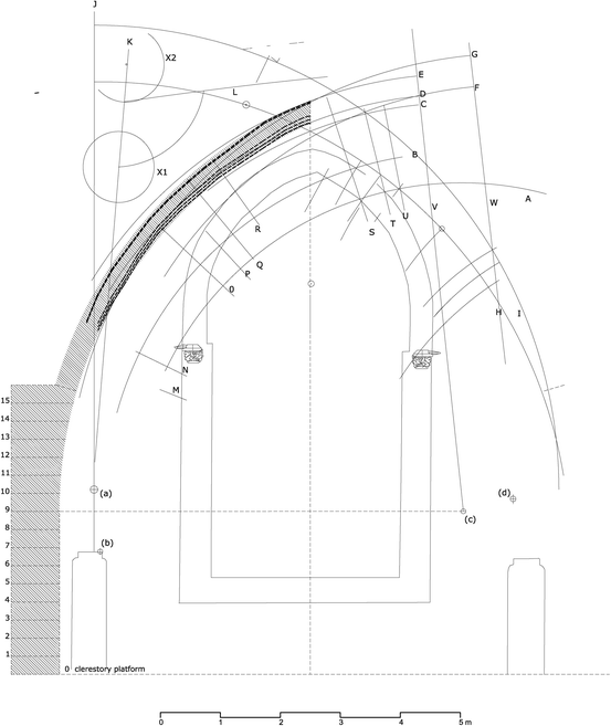
Superposition of the wall rib on the geometric drawing. Drawing by the authors
-
(b)
If we look at the planar projection of the diagonal rib, we see that it is composed of two arches separated by the width of the keystone, opening up the semicircle to achieve the span between the tas-de-charges, which generates a distinctly vertical contact between the keystone and the arch, as indeed we were able to observe during the cleaning works carried out on the vault in 2013. If we superimpose each of these arches on the drawing, we see that it matches curve I, and that the point where the arch and keystone meet coincides with line J. With regard to the centre of the arch, this is situated on the sixth course above the platform where, in theory, the planks for conducting the readjustments in situ would have been located, very close by and at the same height as the scratched drawing (Fig. 14).
Fig. 14 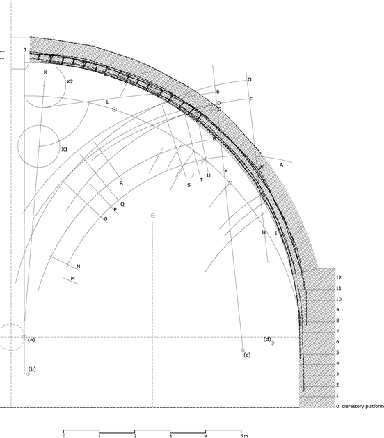
Superposition of the diagonal rib on the geometric drawing. Drawing by the authors
-
(c)
On superposing the planar projection of the long tierceron, we see that it matches arc H, while circle X2 marks the point where it meets the keystone. We also see that the loose lines in the geometric drawing that run perpendicular to arc H mark it at intervals, coinciding—sometimes exactly—with the rib voussoirs. Lastly, the rib impost is also located at the sixth course above the platform, coinciding with the diagonal rib (Fig. 15).
Fig. 15 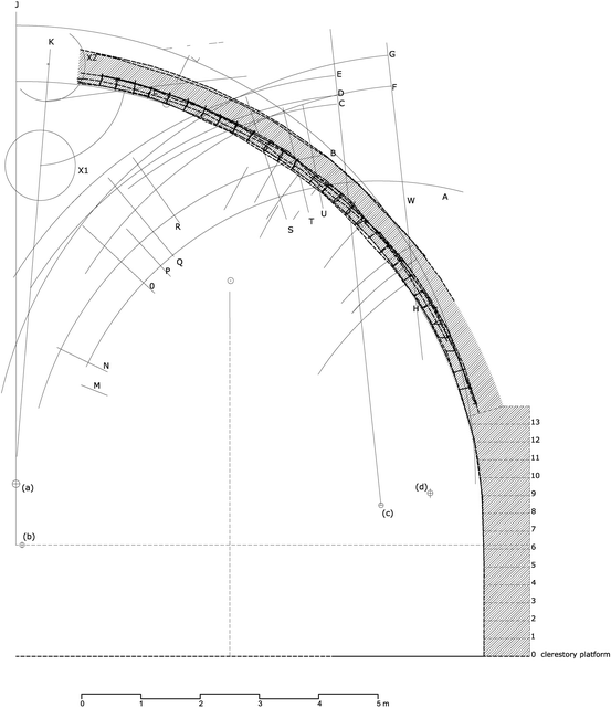
Superposition of the long tierceron on the geometric drawing. Drawing by the authors
-
(d)
As in the previous case, the short tierceron matches arc H, although the top of the curve alters radically as it rises to the keystone. This reflects a common practice during the execution of such works once the positions of the springing point in the tas-de-charge and the point of convergence with the keystone had been established (Martín Talaverano et al. 2012: 23). This meeting point coincides with the circular mark and with one of the radial lines detected in the drawing (Fig. 16).
Fig. 16 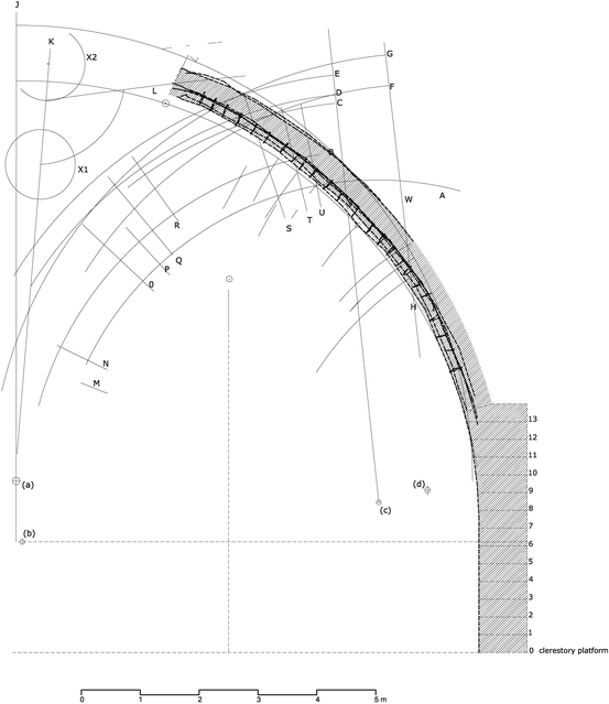
Superposition of the short tierceron on the geometric drawing. Drawing by the authors
-
(e)
Finally, we superposed the rampant rib on the drawing, adjusting the keystone to the axis of symmetry we detected on analysing the wall rib and observing that they were superimposed over straight line L. The length is determined by the axis and straight line J, and curve I also intersects with the axis. The radius is double that of the diagonal rib, which concides with the radius that was implicit in the drawing by Hernán Ruiz (Rabasa Díaz 2000: 127; Fig. 17).
Fig. 17 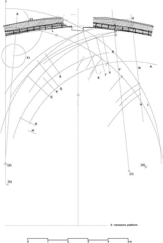
Superposition of the long ridge rib on the geometric drawing. Drawing by the authors


Conclusions
We know that the vault over the chancel was not destroyed by the disasters of 1511 and 1888, and we believe that we have proved that its template was the geometric drawing analysed here, which was made between 1499 and 1504. It might even be the case that prior to 1511 the four vaults that flanked the cupola had the same design and were therefore based on this drawing as well.
It is almost certainly the case that no new drawings were made on the flat roofs after the mid-fifteenth century because all the vaults adopted models that had been tried and tested in the building works, some of the drawings for which have already been published. However, the model for this vault represented a new departure in “Gothic building”, although in fact it anticipated the vault planned for the cupola in the Bidarrueta copy (see footnote 2). The change coincides with the arrival at the cathedral of Master Simón de Colonia, during the archbishopric of Diego Hurtado de Mendoza, which without doubt must have been motivated by the need to introduce changes in the design of the cupola, leading in turn to the need to reinforce the four vaults around it. The only testimony to this decision that has survived to this day is the vault over the chancel, whose design must have been altered during the execution process, therefore requiring a specific geometric drawing to clarify queries about the new parts. Its proximity to the vault was a decisive factor for its construction, while its southern location would have made it easy to read thanks to direct and raking sunlight until midday.
Another factor to bear in mind is that it would have been very easy to use as a large flat working surface for the stonemasons and masters who built the vault and who had references very close by on the other flat roofs, namely the geometric drawings for the preceding level consisting of the main aisles and the aisles flanking the apse. The design workshop, documented from the first half of the fifteenth century, was in all probability located in this same area. The elevation mechanisms may also have occupied this south-east quadrant due to the urban topography, the progress of the works and the “rear” nature of this side of the building. Within this context, the geometric drawing would have played a key role as the nexus for conveying instructions and the meeting point for the various trades, from the carpenters who must have built the formwork to the masons who cut and adjusted the stones to the curve that “holds them steadfastly in the air”, in the words of the illustrious mathematician from Valencia, Tomás Vicente Tosca.
Notes
This was not the case with the vaults built in the Renaissance period, many of which were with the Gothic ones. Interesting examples of the geometric drawings used have survived to this day and shed light on the relationship between the work carried out and the technical and scientific advances of the day, such as the development of optics and perspective or cartographic representation (Pinto Puerto 2001; Ruiz de la Rosa and Rodríguez Estévez 2002; Calvo-López and Alonso-Rodríguez 2010).
Bidaurreta copy is the oldest documented plan of the cathedral of Seville. Acording to recent studies it is a copy of the original plan used to build the cathedral. Bidaurreta is the monastery where the drawing is preserved (Alonso Ruiz and Jiménez Martín 2009).
These CAD drawings produced by the authors are based on all the existing photogrammetric maps of the building created by the School of Arabic Studies in Granada, part of Spain’s Higher Council of Scientific Research (CSIC). All the partial maps are geo-referenced to a system of local coordinates, which provides a very accurate mechanism for relating the interior parts of the building to the exterior parts (Almagro Gorbea and Zúñiga 2007).
“And in order to explain and exemplify this very important matter, I shall demonstrate it on the back as far as I am able so that it may be understood, although these things may be difficult to understand for those who have little practical experience, are not trained in stone cutting and execution, or have not witnessed sufficient closures of rib vaults to acquire the ability to carry them out properly, or have not seen how the cambers, which are the ties between one keystone and the next, are traced in keeping with the templates to ensure that everything is upheld”. Loose translation of some of the expressions in the ancient text on Fol. 24 of Ms 8884, based on the translation of the facsimile (García c. 1681 in Bonet and Chanfón 1991: 67).
“The scaffold is erected at the level where the curves (…) of the diagonal rib on plan GC begin. But since the tas-de-charges will be at a higher level and it will not be possible to reach up to position the ribs above them, a second scaffold like the one marked S will be erected to provide wide, robust planking on which to trace, draught and draw to full scale the entire rib vault, exactly as seen in plan”. Fol. 25 of Ms 8884. (García c. 1681–1683, in Bonet and Chanfón 1991: 68).
Many of the drawings found in this manuscript are sketches of the graphic procedures commonly used in Germany between the late fifteenth and early sixteenth centuries. The collection was bound between 1560 and 1572, with the sketches classified by type. The most interesting drawings for our purpose are the templates for vaults, which form a fairly uniform group. A correlation has recently been established between the types of vaults shown in this manuscript and the vault over the Chapel of La Antigua in Seville Cathedral, designed by Master Simón de Colonia, of German descent, between 1495 and 1510 (Martín Talaverano et al. 2012).
The values shown in the table are approximations to the curve of each rib, since the photogrammetric map is quite faithful in terms of rheological deformations and the readjustments commonly carried out when assembling these ribs. The curves have been adjusted as far as possible to the profiles offered by the lines of the photogrammetric restitution, bearing in mind that these have been traced according to the folds and edges of the curved surfaces of the ribs and the discernible joints between the voussoirs, which are easy to interpret and situate.
The tas-de-charge is situated at varying heights according to the ribs: 10 courses for the diaphragm rib that separates it from the next section of the nave, 12 courses for the diagonal rib, 13 courses for the tiercerons, and 15 courses for the wall rib.
References
Almagro Gorbea, Antonio, Zúñiga, José Ignacio. 2007. Atlas arquitectónico de la catedral de Sevilla. Granada: Cabildo Metropolitano.
Alonso Ruiz, Begoña 2005. “El cimborrio de la magna hispalense y Juan Gil de Hontañón”. Pp. 21–33. Cuarto Congreso Nacional de Historia de la Construcción, Cádiz (2005). Madrid: Sociedad Española de Historia de la Construcción.
Alonso Ruiz, Begoña and Jiménez Martín, Alfonso. 2009. La traça de la iglesia de Sevilla. Seville: Cabildo Metropolitano.
Benítez Bodes, Rosa. 2007. “Notas sobre la evacuación de aguas pluviales en la catedral de Sevilla”. Pp: 247–260. La Piedra Postrera. Volume 2. Seville: Taller Dereceo.
Bucher, François. 1968. “Design in Gothic Architecture: A Preliminary Assessment”. Pp: 49–71 Journal of the Society of Architectural Historians, Vol. 27, No. 1. California: Society of Architectural Historians.
Bucher, François. 1979. The Lodge Books and Sketchbooks of Medieval Architects. Vol. 1. New York: Abaris Books.
Cabezas Gelabert, Lino. 2008. El dibujo como invención. Idear, construir, dibujar: En torno al pensamiento gráfico de los tracistas españoles del siglo XVI. Madrid: Cátedra.
Calvo-López, José and Alonso-Rodríguez, Miguel Angel. 2010. “Perspective versus Stereotomy: From Quattrocento Polyhedral Rings to Sixteenth-Century Spanish Torus Vaults”. Pp: 75-111. Nexus Network Journal – Vol.12, No. 1. Turin: Kim Williams Books.
Fernández Casanova, Adolfo. 1888. Memoria sobre las causas del hundimiento acaecido el 1º de agosto de 1888 en la Catedral de Sevilla. Seville: Imprenta [de la] Plaza de la Constitución.
García, Simón. Compendio. c.1681–1683. Ms 8884. Biblioteca Nacional de Madrid. Facsimile rpt. in: Compendio de Architectura y Simetría de los templos conforme a la medida del cuerpo humano con algunas demostraciones de Geometría, eds. Bonet correa, Antonio and Chanfon olmos, Carlos. Valladolid: Colegio Oficial de Arquitectos de Valladolid. 1991.
Gómez de Terreros Y Guardiola, María del Valle. 1999. “Adolfo Fernández Casanova y la restauración de la Catedral de Sevilla: los procedimientos de ejecución de las obras”. Pp: 41–59. El espíritu de las antiguas fábricas. Escritos de Adolfo Fernández Casanova sobre la Catedral de Sevilla (1888-1901). Seville: Fundación para la Investigación y Difusión de la Arquitectura.
Gómez Martínez, Javier. 1998. El gótico español en la edad moderna. Bóvedas de crucería. Valladolid: Secretariado de publicaciones. Universidad de Valladolid.
Guerrero Vega, José María. 2010. “El informe de 1513 de Alonso Rodríguez”. Pp. 31–74. La catedral gótica de Sevilla. Avla Hernán Rviz XVII. Seville: Taller Dereçeo.
Guerrero Vega, José María and Jimenez sancho, Álvaro. 2013. “Los hastiales de la catedral. Una lectura de su proceso constructivo”. Pp: 25–75. XX edición del Avla Hernan Rviz. La Catedral entre 1434 y 1517: historia y conservación. Seville: Taller Dereçeo.
Guerrero Vega, José María and Pinto Puerto, Francisco. 2014. “Levantamiento y Análisis del remate suroeste de la Puerta de San Cristóbal de la Catedral de Sevilla”. Pp. 83–93. Actas del XII Congreso internacional de Expresión Gráfica Aplicada a la Edificación: Nuevas técnicas, mismos fundamentos. Madrid: Universidad Europea.
Huerta Fernández, Santiago. 2004. Arcos, bóvedas y cúpulas. Geometría y equilibrio en el cálculo tradicional de estructuras de fábrica. Madrid: Instituto Juan de Herrera. Escuela Técnica Superior de Arquitectura de Madrid.
Jiménez Martín, Alfonso, Álvarez Marquez. Carmen, Ruiz Rosa, José Antonio, Ponto Puerto, Francisco, Raya Román, José María, Ampliato Briones, Antonio Luis, Gentil Baldrich, José María, Sanz Serrano, María José. 1997. El libro de Arquitectura de Hernán Ruiz. 2 volumes. Critical edition and facsimile. Seville: Fundación Sevillana de Electricidad.
Jiménez Martín, Alfonso, Pérez Peñaranda, Isabel. 1997. Cartografía de la Montaña Hueca: Notas sobre los planos históricos de la catedral de Sevilla. Cabildo Metropolitano. Sevilla.
Jiménez Martín, Alfonso. 2006. “Las fechas de las formas. Selección crítica de fuentes documentales para la cronología del edificio medieval”. Pp: 15–113. La catedral gótica de Sevilla. Fundación y fábrica de la obra nueva. Seville: Universidad de Sevilla.
Jiménez Martín, Alfonso. 2013. Anatomía de la catedral de Sevilla. Seville: Diputación Provincial.
Jiménez Martín, Alfonso. 2014a. “La catedral de Sevilla y el gótico mediterraneo”. Arquitectura Tardogótica en la Corona de Castilla: Trayectorias e Intercambios. Santander: Universidad de Cantabria.
Jiménez Martín, Alfonso. 2014b. “Palabras en la piedra. Primera aproximación al glosario gótico de la catedral de Sevilla”. XXI edición del Avla Hernán Rviz. Seville: Taller Dereçeo, S.L.
Jiménez Sancho, Álvaro. 2000. “Rellenos cerámicos en las bóvedas de la Catedral de Sevilla”. Pp: 561–567. Actas del Tercer Congreso Nacional de Historia de la Construcción. Madrid, Instituto Juan de Herrera.
López Lorente, Victor Daniel. 2014. “La guerra y el maestro Ysambart (doc. 1399–1434). Reflexiones en torno a la formación y transmisión de conocimientos técnicos en los artesanos de la construcción del tardogótico hispano”. Pp. 410–450. Roda da Fortuna. Revista Eletrônica sobre Antiguidade e Medievo, Volume 3, No. 1–1 (Special Issue). Editorial Staff.
Martín Talaverano, Rafael, Pérez de Los Rios, Carmen, Senent Domínguez, Rosa, 2012. “Late German Gothic Methods of Vault Design and Their Relationships with Spanish Ribbed Vaults”. Pp: 83–90. Nuts and Bolts of Construction History. Vol. 3. Picard. Paris.
Martín Talaverano, Rafael 2011. “Técnicas de diseño germanas de bóvedas de crucería rebajadas”.Pp. 861–871. Actas del Séptimo Congreso Nacional de Historia de la Construcción. Vol. 2. Instituto Juan de Herrera. Escuela Arquitectura Madrid. Madrid.
Palacios Gonzalo, José Carlos 2009. La Cantería medieval. La construcción de la bóveda gótica española. Ediciones Munilla-leira. Madrid.
Pinto Puerto, Francisco and Jiménez Martín, Alfonso. 1993. “Monteas en la Catedral de Sevilla”. Pp: 79–86. EGA. Revista de Expresión Gráfica Arquitectónica (1). Valencia: Universidad de Valencia.
Pinto Puerto, Francisco. 2001. Las esferas de piedra. Sevilla como lugar de encuentro en arte y ciencia del Renacimiento. Seville: Diputación Provincial de Sevilla.
Pinto Puerto, Francisco and Jiménez Sáncho, Álvaro. 2013. “La bóveda de la Capilla Mayor de la Catedral de Sevilla”. Pp: 863–872. Actas del Octavo Congreso Nacional de Historia de la Construcción. Vol. II. Madrid: Instituto Juan de Herrera.
Rabasa Díaz, Enrique. 2000. Forma y construcción en piedra: De la cantería medieval a la estereotomía del siglo XIX. Madrid, Akal.
Rabasa Díaz, Enrique. 2008. “Principios y construcción de las bóvedas de crucería”. Pp: 86–87. Revista Loggia, Year X. No. 20. Valencia.
Ruiz de la Rosa, J.A. 1987. Traza y simetría de la Arquitectura. En la Antigüedad y Medievo. Seville. Universidad de Sevilla.
Ruiz de la Rosa, J.A. 2006. “Dibujos de ejecución. Valor documental y vía de conocimientos de la catedral de Sevilla”. Pp: 297–348. La catedral gótica de Sevilla. Fundación y fábrica de la obra nueva. Seville: Universidad de Sevilla.
Ruiz de la Rosa, J.A. 2007. “Sobre trazas y monteas. Síntesis gráfica de un proceso edificatorio en la Catedral de Sevilla”. Pp: 483–499. La Piedra Postrera. Volume 2. Seville: Taller Dereceo.
Ruiz de la Rosa, José Antonio and Rodríguez Estévez, Juan Clemente. 2002. “Capilla redonda en vuelta redonda” (sic): Aplicación de una propuesta teórica renacentista para la catedral de Sevilla. Pp: 509–516 in IX Congreso Internacional Expresión Gráfica Arquitectónica. Re-visión: Enfoques en docencia e investigación. A Coruña: Universidad de A Coruña.
Shelby, Lon R. 1969. “Setting out the keystones of pointed arches: a note on medieval Baugeometrie”, in Technology and Culture, X.
Tosca, Tomas Vicente. Tratado. c.1727. Facsmile rpt in: Tratado de la montea y corte de cantería. Madrid, eds. Colección Biblioteca Valenciana, Valencia: Librería París-Valencia. 1992.
Author information
Authors and Affiliations
Corresponding author
About this article

Cite this article
Pinto-Puerto, F., Jiménez-Martín, A. Geometric Working Drawing of a Gothic Tierceron Vault in Seville Cathedral. Nexus Netw J 18, 439–466 (2016). https://doi.org/10.1007/s00004-015-0271-7
Published:
Issue Date:
DOI: https://doi.org/10.1007/s00004-015-0271-7