
Abstract
The hierarchical interpolative factorization (HIF) offers an efficient way for solving or preconditioning elliptic partial differential equations. By exploiting locality and low-rank properties of the operators, the HIF achieves quasi-linear complexity for factorizing the discrete positive definite elliptic operator and linear complexity for solving the associated linear system. In this paper, the distributed-memory HIF (DHIF) is introduced as a parallel and distributed-memory implementation of the HIF. The DHIF organizes the processes in a hierarchical structure and keeps the communication as local as possible. The computation complexity is \(O(\frac{N\log N}{P})\) and \(O(\frac{N}{P})\) for constructing and applying the DHIF, respectively, where N is the size of the problem and P is the number of processes. The communication complexity is \(O(\sqrt{P}\log ^3 P)\alpha + O(\frac{N^{2/3}}{\sqrt{P}})\beta \) where \(\alpha \) is the latency and \(\beta \) is the inverse bandwidth. Extensive numerical examples are performed on the NERSC Edison system with up to 8192 processes. The numerical results agree with the complexity analysis and demonstrate the efficiency and scalability of the DHIF.
1 Background
This paper proposes an efficient distributed-memory algorithm for solving elliptic partial differential equations (PDEs) of the form,
with a certain boundary condition, where \(a(x)>0\), b(x) and f(x) are given functions and u(x) is an unknown function. Since this elliptic equation is of fundamental importance to problems in physical sciences, solving (1) effectively has a significant impact in practice. Discretizing this with local schemes such as the finite difference or finite element methods leads to a sparse linear system,
where \(A\in {\mathbb {R}}^{N\times N}\) is a sparse symmetric matrix with \(O(N)\) nonzero entries with N being the number of the discretization points, and u and f are the discrete approximations of the functions u(x) and f(x), respectively. For many practical applications, one often needs to solve (1) on a sufficient fine mesh for which N can be very large, especially for three-dimensional (3D) problems. Hence, there is a practical need for developing fast and parallel algorithms for the efficient solution of (1).
1.1 Previous work
A great deal of effort in the field of scientific computing has been devoted to the efficient solution of (2). Beyond the \(O(N^3)\) complexity naïve matrix inversion approach, one can classify the existing fast algorithms into the following groups.
The first one consists of the sparse direct algorithms, which take advantage of the sparsity of the discrete problem. The most noticeable example in this group is the nested dissection multifrontal method (MF) method [14, 16, 26]. By carefully exploring the sparsity and the locality of the problem, the multifrontal method factorizes the matrix A (and thus \(A^{-1}\)) as a product of sparse lower and upper triangular matrices. For 3D problems, the factorization step costs \(O(N^2)\) operations, while the application step takes \(O(N^{4/3})\) operations. Many parallel implementations [3, 4, 30] of the multifrontal method were proposed and they typically work quite well for problem of moderate size. However, as the problem size goes beyond a couple of millions, most implementations, including the distributed-memory ones, hit severe bottlenecks in memory consumption.
The second group consists of iterative solvers [9, 15, 33, 34], including famous algorithms such as the conjugate gradient (CG) method and the multigrid method. Each iteration of these algorithms typically takes O(N) steps and hence the overall cost for solving (2) is proportional to the number of iterations required for convergence. For problems with smooth coefficient functions a(x) and b(x), the number of iterations typically remains rather small and the optimal linear complexity is achieved. However, if the coefficient functions lack regularity or have high contrast, the iteration number typically grows quite rapidly as the problem size increases.
The third group contains the methods based on structured matrices [6,7,8, 11]. These methods, for example, the \({\mathcal {H}}\)-matrix [18, 20], the \({\mathcal {H}}^2\)-matrix [19], and the hierarchically semi-separable matrix (HSS) [10, 42], are shown to have efficient approximations of linear or quasi-linear complexity for the matrices A and \(A^{-1}\). As a result, the algebraic operations of these matrices are of linear or quasi-linear complexities as well. More specifically, the recursive inversion and the rocket-style inversion [1] are two popular methods for the inverse operation. For distributed-memory implementations, however, the former lacks parallel scalability [24, 25], while the latter demonstrates scalability only for 1D and 2D problems [1]. For 3D problems, these methods typically suffer from large prefactors that make them less efficient for practical large-scale problems.
A recent group of methods explores the idea of integrating the MF method with the hierarchical matrix [17, 21, 28, 32, 38,39,40,41] or block low-rank matrix [2, 35, 36] approach in order to leverage the efficiency of both methods. Instead of directly applying the hierarchical matrix structure to the 3D problems, these methods apply it to the representation of the frontal matrices (i.e., the interactions between the lower-dimensional fronts). These methods are of linear or quasi-linear complexities in theory with much small prefactors. However, due to the combined complexity, the implementation is highly non-trivial and quite difficult for parallelization [27, 43].
More recently, the hierarchical interpolative factorization (HIF) [22, 23] is proposed as a new way for solving elliptic PDEs and integral equations. As compared to the multifrontal method, the HIF includes an extra step of skeletonizing the fronts in order to reduce the size of the dense frontal matrices. Based on the key observation that the number of skeleton points on each front scales linearly as the one-dimensional fronts, the HIF factorizes the matrix A (and thus \(A^{-1}\)) as a product of sparse matrices that contains only \(O(N)\) nonzero entries in total. In addition, the factorization and application of the HIF are of complexities \(O(N\log N)\) and \(O(N)\), respectively, for N being the total number of degrees of freedom (DOFs) in (2). In practice, the HIF shows significant saving in terms of computational resources required for 3D problems.
1.2 Contribution
This paper proposes the first distributed-memory hierarchical interpolative factorization (DHIF) for solving very large-scale problems. In a nutshell, the DHIF organizes the processes in an octree structure in the same way that the HIF partitions the computation domain. In the simplest setting, each leaf node of the computation domain is assigned a single process. Thanks to the locality of the operator in (1), this process only communicates with its neighbors and all algebraic computations are local within the leaf node. At higher levels, each node of the computation domain is associated with a process group that contains all processes in the subtree starting from this node. The computations are all local within this process group via parallel dense linear algebra, and the communications are carried out between neighboring process groups. By following this octree structure, we make sure that both the communication and computations in the distributed-memory HIF are evenly distributed. As a result, the distributed-memory HIF implementation achieves \(O(\frac{N\log N}{P})\) and \(O(\frac{N}{P})\) parallel complexity for constructing and applying the factorization, respectively, where N is the number of DOFs and P is the number of processes.
We have performed extensive numerical tests. The numerical results support the complexity analysis of the distributed-memory HIF and suggest that the DHIF is a scalable method up to thousands of processes and can be applied to solve large-scale elliptic PDEs.
1.3 Organization
The rest of this paper is organized as follows. In Sect. 2, we review the basic tools needed for both HIF and DHIF, and review the sequential HIF. Section 3 presents the DHIF as a parallel extension of the sequential HIF for 3D problems. Complexity analyses for memory usage, computation time, and communication volume are given at the end of this section. The numerical results detailed in Sect. 4 show that the DHIF is applicable to large-scale problems and achieves parallel scalability up to thousands of processes. Finally, Sect. 5 concludes with some extra discussions on future work.
2 Preliminaries
This section reviews the basic tools and the sequential HIF. First, we start by listing the notations that are widely used throughout this paper.
2.1 Notations
In this paper, we adopt MATLAB notations for simple representation of submatrices. For example, given a matrix A and two index sets, \(s_1\) and \(s_2\), \(A(s_1,s_2)\) represents the submatrix of A with the row indices in \(s_1\) and column indices in \(s_2\). The next two examples explore the usage of MATLAB notation “ : .” With the same settings, \(A(s_1,:)\) represents the submatrix of A with row indices in \(s_1\) and all columns. Another usage of notation “ : ” is to create regularly spaced vectors for integer values i and j, for instance, i : j is the same as \([i,i+1,i+2,\dots ,j]\) for \(i\le j\).
In order to simplify the presentation, we consider the problem (1) with periodic boundary condition and assume that the domain \(\varOmega = [0,1)^3\) and is discretized with a grid of size \(n\times n\times n\) for \(n=2^Lm\), where \(L=O(\log n)\) and \(m=O(1)\) are both integers. In the rest of this paper, \(L+1\) is known as the number of levels in the hierarchical structure and L is the level number of the root level. We use \(N = n^3\) to denote the total number of DOFs, which is the dimension of the sparse matrix A in (2). Furthermore, each grid point \({\mathbf x}_{\mathbf j}\) is defined as
where \(h = 1/n\), \({\mathbf j}= (j_1,j_2,j_3)\) and \(0\le j_1,j_2,j_3 < n\).
In order to fully explore the hierarchical structure of the problem, we recursively bipartite each dimension of the grid into \(L+1\) levels. Let the leaf level be level 0 and the root level be level L. At level \(\ell \), a cell indexed with \({\mathbf j}\) is of size \(m2^\ell \times m2^\ell \times m2^\ell \) and each point in the cell is in the range, \(\left[ m2^\ell j_1+(0:m2^\ell -1) \right] \times \left[ m2^\ell j_2+(0:m2^\ell -1) \right] \times \left[ m2^\ell j_3+(0:m2^\ell -1) \right] ,\) for \({\mathbf j}= (j_1,j_2,j_3)\) and \(0\le j_1,j_2,j_3<2^{L-\ell }\). \(C^\ell _{\mathbf j}\) denotes the grid point set of the cell at level \(\ell \) indexed with \({\mathbf j}\).
A cell \(C^\ell _{\mathbf j}\) owns three faces: top, front, and left. Each of these three faces contains the grid points on the first frame in the corresponding direction. For example, the front face contains the grid points in \(\left[ m2^\ell j_1+(0:m2^\ell -1) \right] \times \left[ m2^\ell j_2 \right] \times \left[ m2^\ell j_3+(0:m2^\ell -1) \right] \). Besides these three in-cell faces (top, front, and left) that are owned by a cell, each cell is also adjacent to three out-of-cell faces (bottom, back, right) owned by its neighbors. Each of these three faces contains the grid points on the next to the last frame in the corresponding dimension. As a result, these faces contain DOFs that belong to adjacent cells. For example, the bottom face of \(C^\ell _{\mathbf j}\) contains the grid points in \(\left[ m2^\ell (j_1+1) \right] \times \left[ m2^\ell j_2+(0:m2^\ell -1) \right] \times \left[ m2^\ell j_3+(0:m2^\ell -1) \right] \). These six faces are the surrounding faces of \(C^\ell _{\mathbf j}\). One also defines the interior of \(C^\ell _{\mathbf j}\) to be \(I^\ell _{{\mathbf j}} = \left[ m2^\ell j_1+(1:m2^\ell -1) \right] \times \left[ m2^\ell j_2+(1:m2^\ell -1) \right] \times \left[ m2^\ell j_3+(1:m2^\ell -1) \right] \) for the same \({\mathbf j}= (j_1,j_2,j_3)\) and \(0\le j_1,j_2,j_3 < 2^{L-\ell }\). Figure 1 shows an illustration of a cell, its faces, and its interior. These definitions and notations are summarized in Table 1. Also included here are some notations used for the processes, which will be introduced later.

Cell structure: top, front, left, and interior points are indicated by arrows; bottom, back, and right points are not plotted in the figure; the black dots denote the edge points; the dash line indicates that the front frame is pulled away in order to show the interior points
2.2 Sparse elimination
Suppose that A is a symmetric matrix. The row/column indices of A are partitioned into three sets \(I \bigcup F \bigcup R\) where I refers to the interior point set, F refers to the surrounding face point set, and R refers to the rest point set. We further assume that there is no interaction between the indices in I and the ones in R. As a result, one can write A in the following form
Let the \(LDL^T\) decomposition of \(A_{II}\) be \(A_{II} = L_I D_I L_I^T\), where \(L_I\) is lower triangular matrix with unit diagonal. According to the block Gaussian elimination of A given by (4), one defines the sparse elimination to be
where \(B_{FF} = A_{FF}-A_{FI}A_{II}^{-1}A_{FI}^T\) is the associated Schur complement and the explicit expressions for \(S_I\) is
The sparse elimination removes the interaction between the interior points I and the corresponding surrounding face points F and leaves \(A_{RF}\) and \(A_{RR}\) untouched. We call the entire point set, \(I\bigcup F\bigcup R\), the active point set. Then, after the sparse elimination, the interior points are decoupled from other points, which is conceptually equivalent to eliminate the interior points from the active point set. After this, the new active point set can be regarded as \(F\bigcup R\).
Figure 2 illustrates the impact of the sparse elimination. The dots in the figure represent the active points. Before the sparse elimination (left), edge points, face points, and interior points are active, while after the sparse elimination (right) the interior points are eliminated from the active point set.

Sparse elimination: the interior points are eliminated after the sparse elimination; the rest points are not all plotted in the figure
2.3 Skeletonization
Skeletonization is a tool for eliminating redundant point set from a symmetric matrix that has low-rank off-diagonal blocks. The key step in skeletonization uses the interpolative decomposition [12, 29] of low-rank matrices.
Let A be a symmetric matrix of the form,
where \(A_{RF}\) is a numerically low-rank matrix. The interpolative decomposition of \(A_{RF}\) is (up to a permutation)
where \(T_F\) is the interpolation matrix, \({\widehat{F}}\) is the skeleton point set, \(\bar{\bar{F}}\) is the redundant point set, and \(F = {\widehat{F}}\bigcup \bar{\bar{F}}\). Applying this approximation to A results

and be symmetrically factorized as

where
The factor \(Q_F\) is generated by the block Gaussian elimination, which is defined to be

Meanwhile, the factor \(S_{\bar{\bar{F}}}\) is introduced in the sparse elimination:

where \(L_{\bar{\bar{F}}}\) and \(D_{\bar{\bar{F}}}\) come from the \(LDL^T\) factorization of \(B_{\bar{\bar{F}}\,\bar{\bar{F}}}\), i.e., \(B_{\bar{\bar{F}}\,\bar{\bar{F}}} = L_{\bar{\bar{F}}}D_{\bar{\bar{F}}}L_{\bar{\bar{F}}}^T\). Similar to what happens in Sect. 2.2, the skeletonization eliminates the redundant point set \(\bar{\bar{F}}\) from the active point set.
The point elimination idea of the skeletonization is illustrated in Fig. 3. Before the skeletonization (left), the edge points, interior points, skeleton face points (red), and redundant face points (pink) are all active, while after the skeletonization (right) the redundant face points are eliminated from the active point set.

Skeletonization: the working face is colored by red and pink; red points are the skeleton points on the face, whereas pink points are the redundant points on the face; skeletonization eliminates the redundant points from the active point set
2.4 Sequential HIF
This section reviews the sequential hierarchical interpolative factorization (HIF) for 3D elliptic problems (1) with the periodic boundary condition. Without loss of generality, we discretize (1) with the seven-point stencil on a uniform grid, which is defined in Sect. 2.1. The discrete system is
at each grid point \({\mathbf x}_{\mathbf j}\) for \({\mathbf j}= (j_1,j_2,j_3)\) and \(0\le j_1,j_2,j_3 < n\), where \(a_{\mathbf j}= a({\mathbf x}_{\mathbf j})\), \(b_{\mathbf j}= b({\mathbf x}_{\mathbf j})\), \(f_{\mathbf j}= f({\mathbf x}_{\mathbf j})\), and \(u_{\mathbf j}\) approximates the unknown function u(x) at \({\mathbf x}_{\mathbf j}\). The corresponding linear system is
where A is a sparse SPD matrix if \(b> 0\).
We first introduce the notion of active and inactive DOFs.
-
A set \(\Sigma \) of DOFs of A are called active if \(A_{\Sigma \Sigma }\) is not a diagonal matrix or \(A_{{\bar{\Sigma }}\Sigma }\) is a nonzero matrix;
-
A set \(\Sigma \) of DOFs of A are called inactive if \(A_{\Sigma \Sigma }\) is a diagonal matrix and \(A_{{\bar{\Sigma }}\Sigma }\) is a zero matrix.
Here \({\bar{\Sigma }}\) refers to the complement of the set \(\Sigma \). Sparse elimination and skeletonization provide concrete examples of active and inactive DOFs. For example, sparse elimination turns the indices I from active DOFs of A to inactive DOFs of \({\widetilde{A}}=S_I^T A S_I\) in (5). Skeletonization turns the indices \(\bar{\bar{F}}\) from active DOFs of A to inactive DOFs of \({\widetilde{A}}= S_{\bar{\bar{F}}}^T Q_F^T A Q_FS_{\bar{\bar{F}}}\) in (10).
With these notations, the sequential HIF in [22] is summarized as follows. A more illustrative representation of the sequential HIF is given on the left column of Fig. 5.
-
Preliminary Let \(A^0=A\) be the sparse symmetric matrix in (17), \(\Sigma ^0\) be the initial active DOFs of A, which includes all indices.
-
Level \(\ell \) for \(\ell =0,\ldots ,L-1\).
-
– Preliminary Let \(A^\ell \) denote the matrix before any elimination at level \(\ell \). \(\Sigma ^\ell \) is the corresponding active DOFs. Let us recall the notations in Sect. 2.1. \(C^\ell _{\mathbf j}\) denotes the active DOFs in the cell at level \(\ell \) indexed with \({\mathbf j}\). \({{\mathcal {F}}}^\ell _{\mathbf j}\) and \(I^\ell _{\mathbf j}\) denote the surrounding faces and interior active DOFs in the corresponding cell, respectively.
-
– Sparse elimination We first focus on a single cell at level \(\ell \) indexed with \({\mathbf j}\), i.e., \(C^\ell _{\mathbf j}\). To simplify the notation, we drop the superscript and subscript for now and introduce \(C=C^\ell _{\mathbf j}\), \(I=I^\ell _{\mathbf j}\), \(F={{\mathcal {F}}}^\ell _{\mathbf j}\), and \(R=R^\ell _{\mathbf j}\). Based on the discretization and previous level eliminations, the interior active DOFs interact only with itself and its surrounding faces. The interactions of the interior active DOFs and the rest DOFs are empty and the corresponding matrix is zero, \(A^\ell (R,I) = 0\). Hence, by applying sparse elimination, we have,
$$\begin{aligned} S_I^T A^\ell S_I = \begin{bmatrix} D_I&\quad&\quad \\&\quad B^\ell _{F F}&\quad {\left( A^\ell _{R F} \right) ^T} \\&\quad A^\ell _{R F}&\quad A^\ell _{R R}\\ \end{bmatrix}, \end{aligned}$$(18)where the explicit definitions of \(B^\ell _{F F}\) and \(S_{I}\) are given in the discussion of sparse elimination. This factorization eliminates I from the active DOFs of \(A^\ell \). Looping over all cells \(C^\ell _{\mathbf j}\) at level \(\ell \), we obtain
$$\begin{aligned} {\widetilde{A}}^\ell= & {} \left( \prod _{I\in {{\mathcal {I}}}^\ell }S_{I}\right) ^T A^\ell \left( \prod _{I\in {{\mathcal {I}}}^\ell }S_{I}\right) , \end{aligned}$$(19)$$\begin{aligned} {\widetilde{\Sigma }}^\ell= & {} \Sigma ^\ell \setminus \bigcup _{I\in {{\mathcal {I}}}^\ell } I. \end{aligned}$$(20)Now all the active interior DOFs at level \(\ell \) are eliminated from \(\Sigma ^\ell \).
-
– Skeletonization Each face at level \(\ell \) not only interacts within its own cell but also interacts with faces of neighbor cells. Since the interaction between any two different faces is low rank, this leads us to apply skeletonization. The skeletonization for any face \(F \in {{\mathcal {F}}}^\ell \) gives,
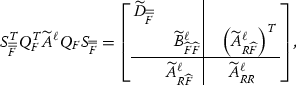 (21)
(21)where \({\widehat{F}}\) is the skeleton DOFs of F, \(\bar{\bar{F}}\) is the redundant DOFs of F, and R refers to the rest DOFs. Due to the elimination from previous levels, |F| scales as \(O(m2^\ell )\) and \({\widetilde{A}}^\ell _{R F}\) contains a nonzero submatrix of size \(O(m2^\ell )\times O(m2^\ell )\). Therefore, the interpolative decomposition can be formed efficiently. Readers are referred to Sect. 2.3 for the explicit forms of each matrix in (21). Looping over all faces at level \(\ell \), we obtain
$$\begin{aligned} A^{\ell +1}\approx & {} \left( \prod _{F\in {{\mathcal {F}}}^\ell }S_{\bar{\bar{F}}} Q_{F}\right) ^T {\widetilde{A}}^\ell \left( \prod _{F\in {{\mathcal {F}}}^\ell }S_{\bar{\bar{F}}} Q_{F}\right) \nonumber \\= & {} \left( \prod _{F\in {{\mathcal {F}}}^\ell }S_{\bar{\bar{F}}} Q_{F}\right) ^T \left( \prod _{I\in {{\mathcal {I}}}^\ell }S_{I}\right) ^T A^\ell \left( \prod _{I\in {{\mathcal {I}}}^\ell }S_{I}\right) \left( \prod _{F\in {{\mathcal {F}}}^\ell }S_{\bar{\bar{F}}} Q_{F}\right) \nonumber \\= & {} {\left( W^\ell \right) ^T} A^\ell W^\ell , \end{aligned}$$(22)where \(W^\ell = \left( \prod _{I\in {{\mathcal {I}}}^\ell }S_{I}\right) \left( \prod _{F\in {{\mathcal {F}}}^\ell }S_{\bar{\bar{F}}} Q_{F}\right) \). The active DOFs for the next level are now defined as,
$$\begin{aligned} \Sigma ^{\ell +1} = {\widetilde{\Sigma }}^\ell \setminus \bigcup _{F\in {{\mathcal {F}}}^\ell } \bar{\bar{F}}= \Sigma ^{\ell } \setminus \left( \left( \bigcup _{I\in {{\mathcal {I}}}^\ell } I\right) \bigcup \left( \bigcup _{F\in {{\mathcal {F}}}^\ell } \bar{\bar{F}}\right) \right) . \end{aligned}$$(23)
-
-
Level L Finally, \(A^L\) and \(\Sigma ^L\) are the matrix and active DOFs at level L. Up to a permutation, \(A^L\) can be factorized as
$$\begin{aligned} A^L = \begin{bmatrix} A^L_{\Sigma ^L\Sigma ^L}&\\&D_R \end{bmatrix} = \begin{bmatrix} L_{\Sigma ^L}&\\&I \end{bmatrix} \begin{bmatrix} D_{\Sigma ^L}&\\&D_R \end{bmatrix} \begin{bmatrix} L_{\Sigma ^L}^T&\\&I \end{bmatrix} := {\left( W^L \right) ^{-T}}D{\left( W^L \right) ^{-1}}.\nonumber \\ \end{aligned}$$(24)Combining all these factorization results
$$\begin{aligned} A \approx {\left( W^0 \right) ^{-T}}\cdots {\left( W^{L-1} \right) ^{-T}}{\left( W^L \right) ^{-T}} D{\left( W^L \right) ^{-1}}{\left( W^{L-1} \right) ^{-1}}\cdots {\left( W^0 \right) ^{-1}} \equiv F\nonumber \\ \end{aligned}$$(25)and
$$\begin{aligned} A^{-1} \approx W^0\cdots W^{L-1} W^L D^{-1} {\left( W^L \right) ^T}{\left( W^{L-1} \right) ^T}\cdots {\left( W^0 \right) ^T} = F^{-1}. \end{aligned}$$(26)\(A^{-1}\) is factorized into a multiplicative sequence of matrices \(W^\ell \) and each \(W^\ell \) corresponding to level \(\ell \) is again a multiplicative sequence of sparse matrices, \(S_I\), \(S_{\bar{\bar{F}}}\) and \(Q_F\). Due to the fact that any \(S_I\), \(S_{\bar{\bar{F}}}\) or \(Q_F\) contains a small non-trivial (i.e., neither identity nor empty) matrix of size \(O(\frac{N^{1/3}}{2^{L-\ell }})\times O(\frac{N^{1/3}}{2^{L-\ell }})\), the overall complexity for strong and applying \(W^\ell \) is \(O(N/2^\ell )\). Hence, the application of the inverse of A is of \(O(N)\) computation and memory complexity.

3 Distributed-memory HIF
This section describes the algorithm for the distributed-memory HIF.
3.1 Process tree
For simplicity, assume that there are \(8^L\) processes. We introduce a process tree that has \(L+1\) levels and resembles the hierarchical structure of the computation domain. Each node of this process tree is called a process group. First at the leaf level, there are \(8^L\) leaf process groups denoted as \(\{p^0_{\mathbf j}\}_{\mathbf j}\). Here \({\mathbf j}=(j_1,j_2,j_3)\), \(0\le j_1,j_2,j_3<2^L\), and the superscript 0 refers to the leaf level (level 0). Each group at this level only contains a single process. Each node at level 1 of the process tree is constructed by merging 8 leaf processes. More precisely, we denote the process group at level 1 as \(p^1_{\mathbf j}\) for \({\mathbf j}=(j_1,j_2,j_3)\), \(0\le j_1,j_2,j_3 < 2^{L-1}\), and \(p^1_{\mathbf j}= \bigcup _{{\lfloor {\mathbf j}_c/2 \rfloor } = {\mathbf j}} p^0_{{\mathbf j}_c}\). Similarly, we recursively define the node at level \(\ell \) as \(p^\ell _{\mathbf j}= \bigcup _{{\lfloor {\mathbf j}_c/2 \rfloor } = {\mathbf j}} p^{\ell -1}_{{\mathbf j}_c}\). Finally, the process group \(p^L_{\mathbf 0}\) at the root includes all processes. Figure 4 illustrates the process tree. Each cube in the process tree is a process group.

Process tree: 64 processes are organized in the process tree
3.2 Distributed-memory method
Same as in Sect. 2.4, we define the \(n \times n\times n\) grid on \(\varOmega =[0,1)^3\) for \(n=m2^L\), where \(m=O(1)\) is a small positive integer and \(L=O(\log N)\) is the level number of the root level. Discretizing (1) with seven-point stencil on the grid provides the linear system \(Au=f\), where A is a sparse \(N\times N\) SPD matrix, \(u\in {\mathbb {R}}^N\) is the unknown function at grid points, and \(f\in {\mathbb {R}}^N\) is the given function at grid points.
Given the process tree (Sect. 3.1) with \(8^L\) processes and the sequential HIF structure (Sect. 2.4), the construction of the distributed-memory hierarchical interpolative factorization (DHIF) consists of the following steps.
-
Preliminary Construct the process tree with \(8^L\) processes. Each process group \(p^0_{\mathbf j}\) owns the data corresponding to cell \(C^0_{\mathbf j}\) and the set of active DOFs in \(C^0_{\mathbf j}\) is denoted as \(\Sigma ^0_{\mathbf j}\), where \({\mathbf j}=(j_1,j_2,j_3)\) and \(0\le j_1,j_2,j_3 < 2^L\). Set \(A^0=A\) and let the process group \(p^0_{\mathbf j}\) own \(A^0(:,\Sigma ^0_{\mathbf j})\), which is a sparse tall-skinny matrix with \(O(N/P)\) nonzero entries.
-
Level \(\ell \) for \(\ell =0,\ldots ,L-1\).
-
– Preliminary Let \(A^\ell \) denote the matrix before any elimination at level \(\ell \). \(\Sigma ^\ell _{\mathbf j}\) denotes the active DOFs owned by the process group \(p^\ell _{\mathbf j}\) for \({\mathbf j}=(j_1,j_2,j_3)\), \(0\le j_1,j_2,j_3 < 2^{L-\ell }\), and the nonzero submatrix of \(A^\ell (:,\Sigma ^\ell _{\mathbf j})\) is distributed among the process group \(p^\ell _{\mathbf j}\) using the two-dimensional block-cyclic distribution.
-
– Sparse elimination The process group \(p^\ell _{\mathbf j}\) owns \(A^\ell (:,\Sigma ^\ell _{\mathbf j})\), which is sufficient for performing sparse elimination for \(I^\ell _{\mathbf j}\). To simplify the notation, we define \(I=I^\ell _{\mathbf j}\) as the active interior DOFs of cell \(C^\ell _{\mathbf j}\), \(F={{\mathcal {F}}}^\ell _{\mathbf j}\) as the surrounding faces, and \(R=R^\ell _{\mathbf j}\) as the rest active DOFs. Sparse elimination at level \(\ell \) within the process group \(p^\ell _{\mathbf j}\) performs essentially
$$\begin{aligned} S_I^{T} A^\ell S_I = \begin{bmatrix} D_I&\quad&\quad \\&\quad B^\ell _{FF}&\quad {\left( A^\ell _{RF} \right) ^T}\\&\quad A^\ell _{RF}&\quad A^\ell _{RR} \end{bmatrix}, \end{aligned}$$(27)where \(B^\ell _{FF} = A^\ell _{FF}-A^\ell _{FI}{\left( A^\ell _{II} \right) ^{-1}} {\left( A^\ell _{FI} \right) ^T}\),
$$\begin{aligned} S_I = \begin{bmatrix} {\left( L^\ell _I \right) ^{-T}}&\quad -{\left( A^\ell _{II} \right) ^{-1}}{\left( A^\ell _{FI} \right) ^T}&\quad \\&\quad I&\quad \\&\quad&\quad I \end{bmatrix} \end{aligned}$$(28)with \(L^\ell _I D_I {\left( L^\ell _I \right) ^T} = A^\ell _{II}\). Since \(A^\ell (:,\Sigma ^\ell _{\mathbf j})\) is owned locally by \(p^\ell _{\mathbf j}\), both \(A^\ell _{FI}\) and \(A^\ell _{II}\) are local matrices. All non-trivial (i.e., neither identity nor empty) submatrices in \(S_I\) are formed locally and stored locally for application. On the other hand, updating on \(A^\ell _{FF}\) requires some communication in the next step.
-
– Communication after sparse elimination After all sparse eliminations are performed, some communication is required to update \(A^\ell _{FF}\) for each cell \(C^\ell _{\mathbf j}\). For the problem (1) with the periodic boundary conditions, each face at level \(\ell \) is the surrounding face of exactly two cells. The owning process groups of these two cells need to communicate with each other to apply the additive updates, a submatrix of \(-A^\ell _{FI}{\left( A^\ell _{II} \right) ^{-1}}{\left( A^\ell _{FI} \right) ^T}\). Once all communications are finished, the parallel sparse elimination does the rest of the computation, which can be conceptually denoted as
$$\begin{aligned} {\begin{matrix} &{} {\widetilde{A}}^\ell = {\left( \prod _{I\in {{\mathcal {I}}}^\ell }S_{I} \right) ^T} A^\ell \left( \prod _{I\in {{\mathcal {I}}}^\ell }S_{I}\right) ,\\ &{} {\widetilde{\Sigma }}^\ell _{\mathbf j}= \Sigma ^\ell _{\mathbf j}\setminus \bigcup _{I\in {{\mathcal {I}}}^\ell }I, \end{matrix}} \end{aligned}$$(29)for \({\mathbf j}=(j_1,j_2,j_3), 0\le j_1,j_2,j_3<2^{L-\ell }\).
-
– Skeletonization For each face F owned by \(p^\ell _{\mathbf j}\), the corresponding matrices \({\widetilde{A}}^\ell (:,F)\) are stored locally. Similar to the parallel sparse elimination part, most operations are local at the process group \(p^\ell _{\mathbf j}\) and can be carried out using the dense parallel linear algebra efficiently. By forming a parallel interpolative decomposition (ID) for \({\widetilde{A}}^\ell _{RF} = \begin{bmatrix} {\widetilde{A}}^\ell _{R{\widehat{F}}} T^\ell _F&{\widetilde{A}}^\ell _{R{\widehat{F}}} \end{bmatrix}\), the parallel skeletonization can be, conceptually, written as
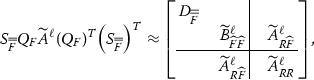 (30)
(30)where the definitions of \(Q_F\) and \(S_{\bar{\bar{F}}}\) are given in the discussion of skeletonization. Since \({\widetilde{A}}^\ell _{\bar{\bar{F}}\,\bar{\bar{F}}}\), \({\widetilde{A}}^\ell _{{\widehat{F}}\bar{\bar{F}}}\), \({\widetilde{A}}^\ell _{{\widehat{F}}{\widehat{F}}}\) and \(T^\ell _{F}\) are all owned by \(p^\ell _{\mathbf j}\), it requires only local operations to form
$$\begin{aligned} \begin{aligned} {\widetilde{B}}^\ell _{\bar{\bar{F}}\,\bar{\bar{F}}}&= {\widetilde{A}}^\ell _{\bar{\bar{F}}\,\bar{\bar{F}}} - {\left( T^\ell _F \right) ^T}{\widetilde{A}}^\ell _{{\widehat{F}}\bar{\bar{F}}} - {\left( {\widetilde{A}}^\ell _{{\widehat{F}}\bar{\bar{F}}} \right) ^T}T^\ell _F + {\left( T^\ell _F \right) ^T}{\widetilde{A}}^\ell _{{\widehat{F}}{\widehat{F}}}T^\ell _F,\\ {\widetilde{B}}^\ell _{{\widehat{F}}\bar{\bar{F}}}&= {\widetilde{A}}^\ell _{{\widehat{F}}\bar{\bar{F}}} - {\widetilde{A}}^\ell _{{\widehat{F}}{\widehat{F}}}T^\ell _F,\\ {\widetilde{B}}^\ell _{{\widehat{F}}{\widehat{F}}}&= {\widetilde{A}}^\ell _{{\widehat{F}}{\widehat{F}}} - {\widetilde{B}}^\ell _{{\widehat{F}}\bar{\bar{F}}}{\left( {\widetilde{B}}^\ell _{\bar{\bar{F}}\,\bar{\bar{F}}} \right) ^{-1}} {\left( {\widetilde{B}}^\ell _{{\widehat{F}}\bar{\bar{F}}} \right) ^T}.\\ \end{aligned} \end{aligned}$$(31)Similarly, \(L_{\bar{\bar{F}}}\), which is the \(LDL^T\) factor of \({\widetilde{B}}_{\bar{\bar{F}}\,\bar{\bar{F}}}\), is also formed within the process group \(p^\ell _{\mathbf j}\). Moreover, since non-trivial blocks in \(Q_F\) and \(S_{\bar{\bar{F}}}\) are both local, this implies that the applications of \(Q_F\) and \(S_{\bar{\bar{F}}}\) are local operations. As a result, the parallel skeletonization factorizes \(A^\ell \) conceptually as
$$\begin{aligned} A^{\ell +1}\approx & {} {\left( \prod _{F\in {{\mathcal {F}}}^\ell }S_{\bar{\bar{F}}}Q_{F} \right) ^T} {\widetilde{A}}^\ell \left( \prod _{F\in {{\mathcal {F}}}^\ell }S_{\bar{\bar{F}}}Q_{F}\right) \nonumber \\= & {} {\left( \prod _{F\in {{\mathcal {F}}}^\ell }S_{\bar{\bar{F}}}Q_{F} \right) ^T} {\left( \prod _{I\in {{\mathcal {I}}}^\ell }S_{I} \right) ^T} A^\ell \left( \prod _{I\in {{\mathcal {I}}}^\ell }S_{I}\right) \left( \prod _{F\in {{\mathcal {F}}}^\ell }S_{\bar{\bar{F}}}Q_{F}\right) \end{aligned}$$(32)and we can define
$$\begin{aligned} {\begin{matrix} W^{\ell } = &{}\,\left( \prod _{I\in {{\mathcal {I}}}^\ell }S_{I}\right) \left( \prod _{F\in {{\mathcal {F}}}^\ell }S_{\bar{\bar{F}}}Q_{F}\right) ,\\ \Sigma ^{\ell +1/2}_{\mathbf j}= &{}\, {\widetilde{\Sigma }}^\ell _{\mathbf j}\setminus \bigcup _{F\in {{\mathcal {F}}}^\ell }\bar{\bar{F}}\\ = &{}\, \Sigma ^\ell _{\mathbf j}\setminus \left( \left( \bigcup _{F\in {{\mathcal {F}}}^\ell }\bar{\bar{F}}\right) \bigcup \left( \bigcup _{I\in {{\mathcal {I}}}^\ell }I\right) \right) . \end{matrix}} \end{aligned}$$(33)We would like to emphasize that the factors \(W^{\ell }\) are evenly distributed among the process groups at level \(\ell \) and that all non-trivial blocks are stored locally.
-
– Merging and redistribution Toward the end of the factorization at level \(\ell \), we need to merge the process groups and redistribute the data associated with the active DOFs in order to prepare for the work at level \(\ell +1\). For each process group at level \(\ell +1\), \(p^{\ell +1}_{\mathbf j}\), for \({\mathbf j}=(j_1,j_2,j_3)\), \(0\le j_1,j_2,j_3 < 2^{L-\ell -1}\), we first form its active DOF set \(\Sigma ^{\ell +1}_{\mathbf j}\) by merging \(\Sigma ^{\ell +1/2}_{{\mathbf j}_c}\) from all its children \(p^\ell _{{\mathbf j}_c}\), where \({\lfloor {\mathbf j}_c/2 \rfloor } = {\mathbf j}\). In addition, \(A^{\ell +1}(:,s^{\ell +1}_{\mathbf j})\) is separately owned by \(\{p^\ell _{{\mathbf j}_c}\}_{{\lfloor {\mathbf j}_c/2 \rfloor }={\mathbf j}}\). A redistribution among \(p^{\ell +1}_{\mathbf j}\) is needed in order to reduce the communication cost for future parallel dense linear algebra. Although this redistribution requires a global communication among \(p^{\ell +1}_{\mathbf j}\), the complexities for message and bandwidth are bounded by the cost for parallel dense linear algebra. Actually, as we shall see in the numerical results, its cost is far lower than that of the parallel dense linear algebra.
-
-
Level L factorization The parallel factorization at level L is quite similar to the sequential one. After factorizations from all previous levels, \(A^L(\Sigma ^L_{\mathbf 0},\Sigma ^L_{\mathbf 0})\) is distributed among \(p^L_{\mathbf 0}\). A parallel \(LDL^T\) factorization of \(A^L_{\Sigma ^L_{\mathbf 0}\Sigma ^L_{\mathbf 0}} = A^L(\Sigma ^L_{\mathbf 0},\Sigma ^L_{\mathbf 0})\) among the processes in \(p^L_{\mathbf 0}\) results
$$\begin{aligned} A^L = \begin{bmatrix} A^L_{\Sigma ^L_{\mathbf 0}\Sigma ^L_{\mathbf 0}}&\\&D_R \end{bmatrix} {=} \begin{bmatrix} L^L_{\Sigma ^L_{\mathbf 0}}&\\&I \end{bmatrix} \begin{bmatrix} D^L_{\Sigma ^L_{\mathbf 0}}&\\&D_R \end{bmatrix} \begin{bmatrix} {\left( L^L_{\Sigma ^L_{\mathbf 0}} \right) ^T}&\\&I \end{bmatrix} = {\left( W^L \right) ^{-T}}D{\left( W^L \right) ^{-1}}.\nonumber \\ \end{aligned}$$(34)Consequently, we form the DHIF for A and \(A^{-1}\) as
$$\begin{aligned} A \approx {\left( W^0 \right) ^{-T}} \cdots {\left( W^{L-1} \right) ^{-T}} {\left( W^L \right) ^{-T}} D {\left( W^L \right) ^{-1}} {\left( W^{L-1} \right) ^{-1}} \cdots {\left( W^0 \right) ^{-1}} \equiv F \end{aligned}$$(35)and
$$\begin{aligned} A^{-1} \approx W^0 \cdots W^{L-1} W^L D^{-1} {\left( W^L \right) ^T} {\left( W^{L-1} \right) ^T} \cdots {\left( W^0 \right) ^T} = F^{-1}. \end{aligned}$$(36)The factors, \(W^\ell \) are evenly distributed among all processes and the application of \(F^{-1}\) is basically a sequence of parallel dense matrix–vector multiplications.

In Fig. 5, we illustrate an example of DHIF for problem of size \(24 \times 24 \times 24\) with \(m=6\) and \(L=2\). The computation is distributed on a process tree with \(4^3=64\) processes. Particularly, Fig. 5 highlights the DOFs owned by process groups involving \(p^0_{(0,1,0)}\), i.e., \(p^0_{(0,1,0)}\), \(p^1_{(0,0,0)}\), and \(p^2_{(0,0,0)}\). Yellow points denote interior active DOFs, blue and brown points denote face active DOFs, and black points denote edge active DOFs. Meanwhile, we also have unfaded and faded groups of points. Unfaded points are owned by the process groups involving \(p^0_{(0,1,0)}\). In other words, \(p^0_{(0,1,0)}\) is the owner for part of the unfaded points. The faded points are owned by other process groups. In the second row and the fourth row, we also see faded brown points, which indicates the required communication to process \(p^0_{(0,1,0)}\). Here Fig. 5 works through two levels of the elimination processes of the DHIF step by step.

Distributed-memory hierarchical interpolative factorization
3.3 Complexity analysis
3.3.1 Memory complexity
There are two places in the distributed algorithm that require heavy memory usage. The first one is to store the original matrix A and its updated version \(A^\ell \) for each level \(\ell \). As we mentioned above in the parallel algorithm, \(A^\ell \) contains at most \(O(N)\) nonzeros and they are evenly distributed on P processes as follows. At level \(\ell \), there are \(8^{L-\ell }\) cells, empirically each of which contains \(O(\frac{N^{1/3}}{2^{L-\ell }})\) active DOFs. Meanwhile, each cell is evenly owned by a process group with \(8^\ell \) processes. Hence, \(O((\frac{N^{1/3}}{2^{L-\ell }})^2)\) nonzero entries of \(A^\ell (:,s^\ell _{\mathbf j})\) are evenly distributed on process group \(p^\ell _{\mathbf j}\) with \(8^\ell \) processes. Overall, there are \(O(8^{L-\ell }\cdot \frac{N^{2/3}}{4^{L-\ell }}) =O(N\cdot 2^{-\ell })\) nonzero entries in \(A^\ell \) evenly distributed on \(8^{L-\ell }\cdot 8^\ell = P\) processes, and each process owns \(O(\frac{N}{P}\cdot 2^{-\ell })\) data for \(A^\ell \). Moreover, the factorization at level \(\ell \) does not rely on the matrix \(A^{\ell '}\) for \(\ell '<\ell -1\). Therefore, the memory cost for storing \(A^\ell \)s is \(O(\frac{N}{P})\) for each process.
The second place is to store the factors \(W^\ell \). It is not difficult to see that the memory cost for each \(W^\ell \) is the same as \(A^{\ell }\). Only non-trivial blocks in \(S_I\), \(Q_F\), and \(S_{\bar{\bar{F}}}\) require storage. Since each of these non-trivial blocks is of size \(O(\frac{N^{1/3}}{2^{L-\ell }})\times O(\frac{N^{1/3}}{2^{L-\ell }})\) and evenly distributed on \(8^\ell \) processes, the overall memory requirement for each \(W^\ell \) on a process is \(O(\frac{N}{P}\cdot 2^{-\ell })\). Therefore, \(O(\frac{N}{P})\) memory is required on each process to store all \(W^\ell \)s.
3.3.2 Computation complexity
The majority of the computation work goes to the construction of \(S_I\), \(Q_{F}\), and \(S_{\bar{\bar{F}}}\). As stated in the previous section, at level \(\ell \), each non-trivial dense matrix in these factors is of size \(O(\frac{N^{1/3}}{2^{L-\ell }})\times O(\frac{N^{1/3}}{2^{L-\ell }})\). The construction adopts the matrix–matrix multiplication, the interpolative decomposition (pivoting QR), the \(LDL^T\) factorization, and the triangular matrix inversion. Each of these operation is of cubic computation complexities and the corresponding parallel computation cost over \(8^\ell \) processes is \(O(\frac{N}{P})\). Since there are only a constant number of these operations per process at a single level, the total computational complexity across all \(O(\log N)\) levels is \(O(\frac{N\log N}{P})\).
The application computational complexity is simply the complexity of applying each nonzero entries in \(W^\ell \)s once, hence, the overall computational complexity is the same as the memory complexity \(O(\frac{N}{P})\).
3.3.3 Communication complexity
The communication complexity is composed of three parts: the communication in the parallel dense linear algebra, the communication after sparse elimination, and the merging and redistribution step within DHIF. It is clear to see that the communication cost for the second part is bounded by either of the rest. Hence, we will simply derive the communication cost for the first and third parts. Here, we adopt the simplified communication model, \(T_\mathrm{comm} = \alpha + \beta \), where \(\alpha \) is the latency and \(\beta \) is the inverse bandwidth.
At level \(\ell \), the parallel dense linear algebra involves the matrix–matrix multiplication, the ID, the \(LDL^T\) factorization, and the triangular matrix inversion for matrices of size \(O(\frac{N^{1/3}}{2^{L-\ell }})\times O(\frac{N^{1/3}}{2^{L-\ell }})\). All these basic operations are carried out on a process group of size \(8^\ell \). Following the discussion in [5], the communication cost for these operations is bounded by \(O(\ell ^3\sqrt{8^\ell })\alpha +O(\frac{N^{2/3}}{4^{L-\ell }8^\ell }\ell )\beta \). Summing over all levels, one can control the communication cost of the parallel dense linear algebra part by
On the other hand, the merging and redistribution step at level \(\ell \) involves \(8^{\ell +1}\) processes and redistributes matrices of size \(O(\frac{N^{1/3}}{2^{L-\ell }}\cdot 8)\times O(\frac{N^{1/3}}{2^{L-\ell }}\cdot 8)\). The current implementation adopts the MPI routine MPI_AllToAll to handle the redistribution on a 2D process mesh. Further, we assume the all-to-all communication sends and receives long messages. The standard upper bound for the cost of this routine is \(O(\sqrt{8^{\ell +1}})\alpha +O(\frac{N^{2/3}}{4^{L-\ell }\sqrt{8^{\ell +1}}}\cdot 64)\beta \) [37]. Therefore, the overall cost is
The complexity of the latency part is not scalable. However, empirically, the cost for this communication is relatively small in the actual running time.
4 Numerical results
Here we present a couple of numerical examples to demonstrate the parallel efficiency of the distributed-memory HIF. The algorithm is implemented in C++11 and all inter-process communication is expressed via the message passing interface (MPI). The distributed-memory dense linear algebra computation is done through the Elemental library [31]. All numerical examples are performed on Edison at the National Energy Research Scientific Computing center (NERSC). The numbers of processes used are always powers of two, ranging from 1 to 8192. The memory allocated for each process is limited to 2 GB.
All numerical results are measured in two ways: the strong scaling and weak scaling. The strong scaling measurement fixes the problem size and increases the number of processes. For a fixed problem size, let \(T^S_{P}\) be the running time of P processes. The strong scaling efficiency is defined as,
In the case that \(T^S_1\) is not available, e.g., the fixed problem cannot fit into the single process memory, we adopt the first available running time, \(T^S_m\), associating with the smallest number of processes, m, as a reference. And the modified strong scaling efficiency is,
The weak scaling measurement fixes the ratio between the problem size and the number of processes. For a fixed ratio, we define the weak scaling efficiency as,
where \(T^W_m\) is the first available running time with m processes and \(T^W_P\) is the running time of P processes.
The notations used in the following tables and figures are listed in Table 2. For simplicity, all examples are defined over \(\varOmega = [0,1)^3\) with periodic boundary condition, discretized on a uniform grid, \(n\times n\times n\), with n being the number of points in each dimension and \(N=n^3\). The PDEs defined in (1) are discretized using the second-order central difference method with seven-point stencil, which is the same as (16). Octrees are adopted to partition the computation domain with the block size at leaf level bounded by 64.
Example 1
We first consider the problem in (1) with \(a(x) \equiv 1\) and \(b(x) \equiv 0.1\). The relative precision of the ID is set to be \(\epsilon = 10^{-3}\).
As shown in Table 3, given the tolerance \(\epsilon = 10^{-3}\) the relative error remains well below this for all N and P. The number of skeleton points on the root level, \(|\Sigma _L|\), grows linearly as the one-dimensional problem size increases. The empirical linear scaling of the root skeleton size strongly supports the quasi-linear scaling for the factorization, linear scaling for the application, and linear scaling for memory cost. The column labeled with \(m_f\) in Table 3, or alternatively Fig. 6c, illustrates the perfect strong scaling for the memory cost. Since the bottleneck for most parallel algorithms is the memory cost, this point is especially important in practice. Perfect distribution of the memory usage allows us to solve very large problem on a massive number of processes, even through the communication penalty on massive parallel computing would be relatively large. The factorization time and application time show good scaling up to thousands of processes. Figure 6a, b presents the strong scaling plot for the running time of factorization and application, respectively. Together with Fig. 6d, which illustrates the timing for each part of the factorization, we conclude that the communication cost beside the parallel dense linear algebra (labeled with “El”) remains small comparing to the cost of the parallel dense linear algebra. It is the parallel dense linear algebra part that stops the strong scaling. As it is also well known that parallel dense linear algebra achieves good weak scaling, so does our DHIF implementation. Finally, the last column of Table 3 shows the number of iterations for solving \(Au=f\) using the GMRES algorithm with a relative tolerance of \(10^{-12}\) and with the DHIF as a preconditioner. As the numbers in the entire column are equal to 6, this shows that DHIF serves an excellent preconditioner with the iteration number almost independent of the problem size.

Example 1. a is the scaling plot for the DHIF factorization time, the solid lines indicate the weak scaling results, the dashed lines are the strong scaling results, and the dotted lines are the reference lines for perfect strong scaling; the line style applies to all figures below; b is the strong scaling for the DHIF application time; c is the strong scaling for the DHIF peak memory usage; d shows a stacked bar plot for factorization time for fixed ratio between the problem size and the number of processes
Example 2
The second example is a problem of (1) with high-contrast random field a(x) and \(b(x) \equiv 0.1\). The high-contrast random field a(x) is defined as follows,
-
1.
Generate uniform random value \(a_{\mathbf j}\) between 0 and 1 for each discretization point;
-
2.
Convolve the random value \(a_{\mathbf j}\) with an isotropic three-dimensional Gaussian with standard deviation 1;
-
3.
Quantize the field via
$$\begin{aligned} a_{\mathbf j}= \left\{ \begin{array}{ll} 0.1, &{} a_{\mathbf j}\le 0.5\\ 1000, &{} a_{\mathbf j}> 0.5\\ \end{array} \right. . \end{aligned}$$(42)
The given tolerance is set to be \(10^{-5}\).
Figure 7 shows a slice in a realization of the random field. The corresponding matrix A is clearly of high contrast. Solving such a problem is harder than Example 1 due to the raise of the condition number. The performance results of our algorithm are presented in Table 4. As we expect, the relative error for solving is lower than that in Table 3 and the number of iterations in GMRES is higher.

A slice in a random field realization of size \(128^3\)
Table 4 and Fig. 8 demonstrate the efficiency of the DHIF for high-contrast random field. Almost all comments regarding the numerical results in Example 1 apply here. To focus on the difference between Example 1 and Example 2, the most noticeable difference is about the relative error, \(e_s\). Though we give a higher relative precision \(\epsilon = 10^{-5}\), the relative error for Example 2 is about \(3\,\times \,10^{-3}\), which is about ten times larger than \(e_s\) in Example 1. The reason for the decrease of accuracy is most likely the increase of the condition number for Example 2. This also increases the number of iterations in GMRES. However, both \(e_s\) and \(n_\mathrm{iter}\) remain roughly constant for varying problem sizes. This means that DHIF still serves as a robust and efficient solver and preconditioner for such problems. Another difference is the number of skeleton points on the root level, \(|\Sigma _L|\). Due to the fact that the field a(x) is random, and different rows in Table 4 actually adopt different realizations, the small fluctuation of \(|\Sigma _L|\) for the same N and different P is expected. Overall \(|\Sigma _L|\) still grows linearly as \(n = N^{1/3}\) increases. This again supports the complexity analysis given above.

Example 2. a provides a scaling plot for DHIF factorization time; b is the strong scaling for DHIF application time; c is the strong scaling for DHIF peak memory usage; d shows a stacked bar plot for factorization time for fixed ratio between problem size and number of processes
Example 3
The third example provides a concrete comparison between the proposed DHIF and multigrid method (hypre [13]). The problem behaves similar as example 2 without randomness, (1) with high-contrast field a(x) and \(b(x) \equiv 0.1\). The high-contrast field a(x) is defined as follows,
where n is the number of grid points on each dimension.
We adopt GMRES iterative method in both DHIF and hypre to solve the elliptic problem to a relative error \(10^{-12}\). The given tolerance in DHIF is set to be \(10^{-4}\). And SMG interface in hypre is used as preconditioner for the problem on regular grids. The numerical results for DHIF and hypre are given in Table 5.
As we can read from Table 5, there are a few advantages of DHIF over hypre in the given settings. First, DHIF is faster than hypre’s SMG except for small problems with small numbers of processes. And the number of iterations grows as the problem size grows in hypre, while it remains almost the same in DHIF. In truly large problems, the advantages of DHIF are more pronounced. Second, the scalability of DHIF appears to be better than that of hypre’s SMG. Finally, DHIF only requires powers of two numbers of processes, whereas hypre’s SMG requires powers of eight for 3D problems.
5 Conclusion
In this paper, we introduced the distributed-memory hierarchical interpolative factorization (DHIF) for solving discretized elliptic partial differential equations in 3D. The computational and memory complexity for DHIF is
respectively, where N is the total number of DOFs and P is the number of processes. The communication cost is
where \(\alpha \) is the latency and \(\beta \) is the inverse bandwidth. Not only the factorization is efficient, the application can also be done in \(O(\frac{N}{P})\) operations. Numerical examples in Sect. 4 illustrate the efficiency and parallel scaling of the algorithm. The results show that DHIF can be used both as a direct solver and as an efficient preconditioner for iterative solvers.
We have described the algorithm using the periodic boundary condition in order to simplify the presentation. However, the implementation can be extended in a straightforward way to problems with other type of boundary conditions. The discretization adopted here is the standard Cartesian grid. For more general discretizations such as finite element methods on unstructured meshes, one can generalize the current implementation by combining with the idea proposed in [36].
Here we have only considered the parallelization of the HIF for differential equations. As shown in [22], the HIF is also applicable to solving integral equations with non-oscillatory kernels. Parallelization of this algorithm is also of practical importance.
Acknowledgements
Y. Li and L. Ying are partially supported by the National Science Foundation under award DMS-1521830 and the U.S. Department of Energy’s Advanced Scientific Computing Research program under award DE-FC02-13ER26134/DE-SC0009409. The authors would like to thank K. Ho, V. Minden, A. Benson, and A. Damle for helpful discussions. We especially thank J. Poulson for the parallel dense linear algebra package Elemental. We acknowledge the Texas Advanced Computing Center (TACC) at The University of Texas at Austin (URL: http://www.tacc.utexas.edu) for providing HPC resources that have contributed to the research results reported in the early versions of this paper. This research, in the current version, used resources of the National Energy Research Scientific Computing Center, a DOE Office of Science User Facility supported by the Office of Science of the U.S. Department of Energy under Contract No. DE-AC02-05CH11231.
References
Ambikasaran, S., Darve, E.: An \(\cal{O}(N \log N)\) fast direct solver for partial hierarchically semi-separable matrices: with application to radial basis function interpolation. SIAM J. Sci. Comput. 57(3), 477–501 (2013)
Amestoy, P., Ashcraft, C., Boiteau, O., Buttari, A., L’Excellent, J.-Y., Weisbecker, C.: Improving multifrontal methods by means of block low-rank representations. SIAM J. Sci. Comput. 37(3), A1451–A1474 (2015)
Amestoy, P.R., Duff, I.S., L’Excellent, J.-Y.: Multifrontal parallel distributed symmetric and unsymmetric solvers. Comput. Methods Appl. Mech. Eng. 184(24), 501–520 (2000)
Amestoy, P.R., Duff, I.S., L’Excellent, J.-Y., Koster, J.: A fully asynchronous multifrontal solver using distributed dynamic scheduling. SIAM J. Matrix Anal. Appl. 23(1), 15–41 (2001)
Ballard, G., Demmel, J., Holtz, O., Schwartz, O.: Minimizing communication in numerical linear algebra. SIAM J. Matrix Anal. Appl. 32(3), 866–901 (2011)
Bebendorf, M.: Efficient inversion of the Galerkin matrix of general second-order elliptic operators with nonsmooth coefficients. Math. Comput. 74(251), 1179–1199 (2005)
Bebendorf, M., Hackbusch, W.: Existence of \(\cal{H}\)-matrix approximants to the inverse FE-matrix of elliptic operators with \(L^\infty \)-coefficients. Numer. Math. 95(1), 1–28 (2003)
Börm, S.: Approximation of solution operators of elliptic partial differential equations by \(\cal{H}\)- and \(\cal{H}^2\)-matrices. Numer. Math. 115(2), 165–193 (2010)
Briggs, W.L., Henson, V.E., McCormick, S.F.: A Multigrid Tutorial, 2nd edn. Society for Industrial and Applied Mathematics (2000). doi:10.1137/1.9780898719505
Chandrasekaran, S., Dewilde, P., Gu, M., Pals, T., Sun, X., van der Veen, A.-J., White, D.: Some fast algorithms for sequentially semiseparable representations. SIAM J. Matrix Anal. Appl. 27(2), 341–364 (2005)
Chandrasekaran, S., Dewilde, P., Gu, M., Somasunderam, N.: On the numerical rank of the off-diagonal blocks of Schur complements of discretized elliptic PDEs. SIAM J. Matrix Anal. Appl. 31(5), 2261–2290 (2010)
Cheng, H., Gimbutas, Z., Martinsson, P.-G., Rokhlin, V.: On the compression of low rank matrices. SIAM J. Sci. Comput. 26(4), 1389–1404 (2005)
Chow, E., Falgout, R.D., Hu, J.J., Tuminaro, R.S., and Yang, U.M.: A survey of parallelization techniques for multigrid solvers. Parallel Process. Sci. Comput., chapter 10, pp. 179–201. Society for Industrial and Applied Mathematics (2006)
Duff, I.S., Reid, J.K.: The multifrontal solution of indefinite sparse symmetric linear equations. ACM Trans. Math. Softw. 9(3), 302–325 (1983)
Falgout, R.D., Jones, J.E.: Multigrid on massively parallel architectures. In: Dick, E., Riemslagh, K., Vierendeels, J. (eds.) Multigrid Methods VI. Lecture Notes in Computational Science and Engineering, vol. 14, pp. 101–107. Springer, Berlin (2000). doi:10.1007/978-3-642-58312-4_13
George, A.: Nested dissection of a regular finite element mesh. SIAM J. Numer. Anal. 10(2), 345–363 (1973)
Gillman, A., Martinsson, P.-G.: A direct solver with \(O(N)\) complexity for variable coefficient elliptic PDEs discretized via a high-order composite spectral collocation method. SIAM J. Sci. Comput. 36(4), A2023–A2046 (2014)
Hackbusch, W.: A sparse matrix arithmetic based on \(\cal{H}\)-matrices. I. Introduction to \(\cal{H}\)-matrices. Computing 62(2), 89–108 (1999)
Hackbusch, W., Börm, S.: Data-sparse approximation by adaptive \(\cal{H}^2\)-matrices. Computing 69(1), 1–35 (2002)
Hackbusch, W., Khoromskij, B.N.: A sparse \(\cal{H}\)-matrix arithmetic. II. Application to multi-dimensional problems. Computing 64(1), 21–47 (2000)
Hao, S., Martinsson, P.-G.: A direct solver for elliptic PDEs in three dimensions based on hierarchical merging of Poincaré-Steklov operators. J. Comput. Appl. Math. 308, 419–434 (2016). doi:10.1016/j.cam.2016.05.013
Ho, K.L., Ying, L.: Hierarchical interpolative factorization for elliptic operators: differential equations. Commun. Pure Appl. Math. 69(8), 1415–1451 (2016). doi:10.1002/cpa.21582
Ho, K.L., Ying, L.: Hierarchical interpolative factorization for elliptic operators: integral equations. Commun. Pure Appl. Math. 69(7), 1314–1353 (2016)
Izadi, M.: Parallel \(\cal{H}\)-matrix arithmetic on distributed-memory systems. Comput. Vis. Sci. 15(2), 87–97 (2012)
Kriemann, R.: \(\cal{H}\)-LU factorization on many-core systems. Comput. Vis. Sci. 16(3), 105 (2013)
Liu, J.W.H.: The multifrontal method for sparse matrix solution: theory and practice. SIAM Rev. 34(1), 82–109 (1992)
Liu, X., Xia, J., Hoop, M.V.D.E.: Parallel randomized and matrix-free direct solvers for large structured dense linear systems. SIAM J. Sci. Comput. 38(5), 1–32 (2016)
Martinsson, P.-G.: A fast direct solver for a class of elliptic partial differential equations. SIAM J. Sci. Comput. 38(3), 316–330 (2009)
Martinsson, P.G.: Blocked rank-revealing QR factorizations: how randomized sampling can be used to avoid single-vector pivoting. arXiv:1505.08115 (2015)
Poulson, J., Engquist, B., Li, S., Ying, L.: A parallel sweeping preconditioner for heterogeneous 3D Helmholtz equations. SIAM J. Sci. Comput. 35(3), C194–C212 (2013)
Poulson, J., Marker, B., van de Geijn, R.A., Hammond, J.R., Romero, N.A.: Elemental: a new framework for distributed memory dense matrix computations. ACM Trans. Math. Softw. 39(2), 13:1–13:24 (2013)
Pouransari, H., Coulier, P., Darve, E.: Fast hierarchical solvers for sparse matrices using low-rank approximation. arXiv:1510.07363 (2016)
Saad, Y.: Parallel iterative methods for sparse linear systems. Stud. Comput. Math. 8, 423–440 (2001)
Saad, Y.: Iterative Methods for Sparse Linear Systems, 2nd edn. Society for Industrial and Applied Mathematics (2003). doi:10.1137/1.9780898718003
Schmitz, P.G., Ying, L.: A fast direct solver for elliptic problems on general meshes in 2D. J. Comput. Phys. 231(4), 1314–1338 (2012)
Schmitz, P.G., Ying, L.: A fast nested dissection solver for Cartesian 3D elliptic problems using hierarchical matrices. J. Comput. Phys. 258, 227–245 (2014)
Scott, D.S.: Efficient all-to-all communication patterns in hypercube and mesh topologies. In: Distributed Memory Computing Conference, pp. 398–403. IEEE (1991)
Wang, S., Li, X.S., Rouet, F.H., Xia, J., De Hoop, M.V.: A parallel geometric multifrontal solver using hierarchically semiseparable structure. ACM Trans. Math. Softw. 42(3), 21:1–21:21 (2016)
Xia, J.: Efficient structured multifrontal factorization for general large sparse matrices. SIAM J. Sci. Comput. 35(2), A832–A860 (2013)
Xia, J.: Randomized sparse direct solvers. SIAM J. Matrix Anal. Appl. 34(1), 197–227 (2013)
Xia, J., Chandrasekaran, S., Gu, M., Li, X.S.: Superfast multifrontal method for large structured linear systems of equations. SIAM J. Matrix Anal. Appl. 31(3), 1382–1411 (2009)
Xia, J., Chandrasekaran, S., Gu, M., Li, X.S.: Fast algorithms for hierarchically semiseparable matrices. Numer. Linear Algebr. Appl. 17(6), 953–976 (2010)
Xin, Z., Xia, J., De Hoop, M.V., Cauley, S., Balakrishnan, V.: A distributed-memory randomized structured multifrontal method for sparse direct solutions. Purdue GMIG Rep. 14(17), 1–25 (2014)
Author information
Authors and Affiliations
Corresponding author
Rights and permissions
Open Access This article is distributed under the terms of the Creative Commons Attribution 4.0 International License (http://creativecommons.org/licenses/by/4.0/), which permits unrestricted use, distribution, and reproduction in any medium, provided you give appropriate credit to the original author(s) and the source, provide a link to the Creative Commons license, and indicate if changes were made.
About this article

Cite this article
Li, Y., Ying, L. Distributed-memory hierarchical interpolative factorization. Res Math Sci 4, 12 (2017). https://doi.org/10.1186/s40687-017-0100-6
Received:
Accepted:
Published:
DOI: https://doi.org/10.1186/s40687-017-0100-6