
Abstract
The dataset presented here contains recordings of electroencephalogram (EEG) and electrooculogram (EOG) from four advanced locked-in state (LIS) patients suffering from ALS (amyotrophic lateral sclerosis). These patients could no longer use commercial eye-trackers, but they could still move their eyes and used the remnant oculomotor activity to select letters to form words and sentences using a novel auditory communication system. Data were recorded from four patients during a variable range of visits (from 2 to 10), each visit comprised of 3.22 ± 1.21 days and consisted of 5.57 ± 2.61 sessions recorded per day. The patients performed a succession of different sessions, namely, Training, Feedback, Copy spelling, and Free spelling. The dataset provides an insight into the progression of ALS and presents a valuable opportunity to design and improve assistive and alternative communication technologies and brain-computer interfaces. It might also help redefine the course of progression in ALS, thereby improving clinical judgement and treatment.
Measurement(s) | eye movement measurement • brain measurement • muscle electrophysiology trait |
Technology Type(s) | electrooculography • electroencephalography (EEG) • electromyography |
Factor Type(s) | auditory stimuli • amyotrophic lateral sclerosis patient in locked-in state |
Sample Characteristic - Organism | Homo sapiens |
Machine-accessible metadata file describing the reported data: https://doi.org/10.6084/m9.figshare.13148762
Background & Summary
Amyotrophic lateral sclerosis (ALS) is a neurodegenerative disorder that, in its final stages, paralyzes affected individuals impairing their ability to communicate1,2,3,4. Those patients with intact consciousness, voluntary eye movement control, who can blink their eyes or twitch their muscles are said to be in a locked-in state (LIS)5,6. Patients in LIS rely on eye-tracking based assistive and augmentative communication (AAC) technologies to communicate7,8. In the case of patients who survive attached to life-support systems, the progression of the disease ultimately destroys oculomotor control, leading to the loss of gaze-fixation and impeding the use of eye-tracking based communication technologies9,10,11. Nevertheless, even in the late stages of this condition, some remaining controllable muscles of the eyes continue to function for an unspecified length of time, which can be used to provide a means of communication to these patients11,12.
An auditory electrooculogram (EOG) based communication system12 was developed to provide a means of communication to ALS patients without gaze-fixation and who were unable to use the commercial AAC eye-tracking devices, but who had remnant oculomotor control to form words, phrases, and sentences using the system described in Tonin & Jaramillo-Gonzalez et al.12. Four ALS patients with progressively decreasing EOG signal amplitude in the range of ±200 μV to ±40 μV were able to select letters to construct words to form sentences and hence communicate freely using an auditory speller system. The auditory speller system is based on a binary system in which a patient is asked to respond to auditory questions by moving the eyes to say “yes” and not moving the eyes to say “no”. The system must use the auditory modality because, in these patients, vision is often impaired due to drying and necrosis of the cornea and the partly or fully paralyzed eye-muscles. The study design and paradigm are described in detail in the Methods section.
This data descriptor outlines the EEG and EOG recordings from four different patients recorded during their use of the auditory communication system, having first trained progressively, and then ultimately controlling the system to communicate. Electromyography (EMG) recordings are available for some sessions, according to the clinical conditions.
There have been other studies with similar goals, but only one has an available online dataset13, with different features. To our knowledge, in the available open-access specialized repositories14,15,16, there are no datasets with similar properties to the one described here. It must be emphasized that the data described here are both the EOG and EEG signals recorded with a dedicated set of electrodes for each type of signal simultaneously. These EEG and EOG data are recorded from patients with ALS in the most advanced stage, whose disease progression is not well defined and is, to a certain extent, unknown. The data highlight a phase in ALS where communication becomes difficult and gradually impossible with existing commercial AAC. It includes recordings of over the course of a year during which one of the users became unable to use the system because of disease progression. As a consequence, we believe that the study of this dataset might help towards improving the clinical definition of ALS in its very advanced state, the testing of hypotheses on the brain’s electrophysiological changes during this progression and evaluating the impact of advanced ALS on the cognitive state of the patients. Nevertheless, even though the data is quite specific, further investigation of the data can support novel clinical and therapeutic practices. It could help develop augmentative and alternative assistive communication technologies and brain-computer interfaces that can be generalized to other types of disorders and patients with pervasive communication deficits and motor impairments due to CNS damage, such as stroke or high spinal cord injury. Lastly, although the system can be considered successful in enabling communication, other analytical methods can still improve the system’s speed and efficiency, for example, offline testing of other feature extraction methods or testing and comparing the performance with different machine-learning methods to classify the patients’ response.
Methods
The Internal Review Board of the Medical Faculty of the University of Tubingen approved the experiment reported in this study. The study was performed according to guidelines established by the Medical Faculty of the University of Tubingen. The patient, or the patient’s legal representative, gave informed consent with permission to publish the data. The clinical trial registration number is: ClinicalTrials.gov - Identifier: NCT02980380. The methods described here are complementary to an in-depth description of the results derived from this dataset that have been presented in related work12.
Participating patients
Four ALS patients with amyotrophic lateral sclerosis with a functional rating scale revised (ALSFRS-R)17 score of 0 in the locked-in state (LIS) were visited on subsequent months starting from Feb 2018 to May 2019. Team members travelled to the patient’s home to perform the communication sessions, depending on the health status and convenience of the patient. The medical history of patients is described in our related work12. Every visit (V), lasted for a few days (D), during which the patient performed different session (S), as detailed in the Online-only Tables 1–4, with the precise dates of all the visits and details of the sessions.
Auditory communication system
Prerequisites for performing the study
In agreement with the patients’ caretakers and considering the patients’ health and wellness and optimization of resources, it was established that the visits should be performed every two months approximately, with each visit no longer than four days. However, on some occasions the condition of the patients led to shorter visits, from three days to a single day. (see Online-only Tables 1–4). For each visit, guided by the same criteria of health and wellness of the patient, two team members transported all equipment and set up all systems in the patient’s home or accommodation.
Before the beginning of the study, at least 100 questions with known “yes” or “no” answers were formulated and recorded by a family member or caretaker in their own voice, in close proximity to the patient. Each question with a “yes” answer is paired with a similar question with “no” answer (e.g., “Paris is the capital of France” and “Berlin is the capital of France”). Each question is saved as an audio file with an explicit identifier, a question with a “yes” answer is saved with a 001_NUMBER identifier, and a question with “no” answer is saved with a 002_NUMBER identifier. The value of the label NUMBER is the same for a semantically paired sentence. The same procedure was repeated with biographical-related questions with at least 100 for every patient. Sentences are then stored on a laptop and accessed and played by the communication system during the sessions.
Study and paradigm
The study consisted of patients performing four different types of sessions, namely, Training, Feedback, Copy speller, and Free speller session, to train and enable the patient to employ an oculomotor strategy to control the spelling system successfully. During the visit, the patient performed different sessions, as depicted in Fig. 1. The patients developed a strategy to respond during successive trials to an auditory question (the questions previously recorded) by moving the eyes to say “yes” and by not moving the eyes to say “no”. To control the activities during the trials, specific paradigms were designed for the different sessions, as depicted in Fig. 2.
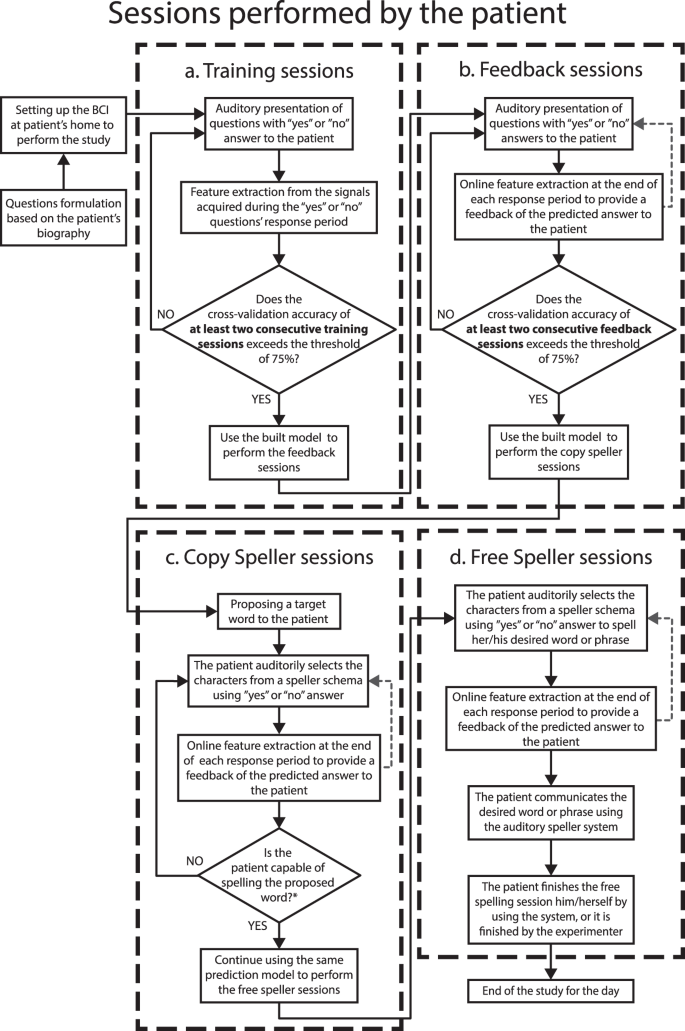
The procedure performed during a single day. The figure depicts the sequence of the types of sessions performed by patients and the criteria to progress from one type of session to the next. The patients first performed the Training sessions during which the patient learned to move his/her eyes to generate the signal to control the auditory communication system. At the end of the Training session, a classification model was built, and when the accuracy of the built model was greater than 75% the patients performed the feedback session. During the feedback sessions the patients were provided the feedback of their response, i.e., whether their answer was classified as “yes” or “no”. When the feedback accuracy exceeded 75% the patients first performed a copy speller session and then a free speller during which they could spell whatever they desired.

Different types of trials in the study. (a) Paradigm describing the sequence of events and sequence of the triggers’ labels used in a single trial for the Training and Feedback sessions. In these types of sessions, 20 questions with “yes” and “no” answers, known by the patient, are presented in a pseudo-random order. (b) Paradigm describing the sequence of events and sequence of the triggers’ labels used during a single trial for the Copy and Free spelling sessions. In these sessions, instead of questions, the patient is presented with options that allow him/her to navigate through his/her predetermined spelling scheme (e.g., sectors, letters). For both spelling sessions, the limit in the number of trials depends only on the patient’s attempts to spell the given target (i.e., Copy speller sessions) or her/his desired sentence (i.e., Open speller sessions). For any type of session recorded, the recording’s start and end are indicated by an “S 9” and an “S 15” trigger.
The different sessions performed by the patients are described below.
-
a.
Training session
The study on a single day always started with Training sessions during which the patients were instructed to listen to a sequence of 20 personal questions consisting of 10 sentences with a “yes” answer and 10 with “no” answer, presented in pseudo-random order. After the system presents an auditory question, patients are asked to move their eyes to respond “yes” and not to move the eyes to respond “no” during a response time window. The duration of the response segment depended on the patient’s performance, i.e., if the patient could move his/her eye with ease, the duration was kept shorter and vice versa. Therefore, this window has a range from 3 to 10 seconds. For each Training session, the set of triggers indicating the sequence of events were recorded on the raw file, using the labels shown in Fig. 2a. Alongside, the system creates a questions sequence text file (Block_X_senlist.txt) that includes the list of identifiers of the presented audio/question files during the session (e.g., 001_13012a.wav), including also the label of the corresponding type of answer (“0” for sentences with “no” as an answer, and “1” for sentences with “yes” as an answer). The.txt lists are included inside the raw data folder structure, as described in the section Data Records. After at least two consecutive Training sessions with a classification accuracy result greater than 75%, the patient progresses to the Feedback sessions (see Fig. 1).
-
b.
Feedback session
As in the Training session, the patients were presented with a sequence of a familiar question, but, at the end of the response segment, they were provided with auditory feedback as to whether their answer was recognized as “yes” or “no” by the system. For each Feedback session, the triggers indicating the events’ sequence were recorded on the raw file, using the labels shown in Fig. 2a. The system creates a sentence list (Block_X_senlist.txt) in the same way it was created for the Training sessions. In the case of Feedback sessions, in addition to the sequence of the questions text file, the system creates a result file (Date_result_f1_X.txt) listing the predicted results, i.e., “1” if the answer was recognized as “no”, “0” if the answer was recognized as “yes”, and “2” if the answer was unable to be classified by the system. The system gives the patient auditory feedback with the sentence: “Your answer was classified as yes/no”. Both.txt lists are also included inside the raw data folder structure, as described in the section Data Records. After at least two consecutive Feedback sessions with a classification accuracy result greater than 75%, the patient progresses to the Copy spelling sessions (see Fig. 1).
The sequence of events and triggers (with their labels) for a single trial of the Training and Feedback sessions is depicted in Fig. 2a. Each of these trials consists of the segment of baseline (i.e., no sound presented), stimulus, during which the question is presented auditorily to the patients, followed by the segment of response time, in which the patient moves or does not move the eye according to his/her answer, and lastly the segment of feedback. For a Training session trail, the feedback is “thank you” to mark the end of the response while for a Feedback session trail, the feedback is “yes” or “no” depending on the answer classified by the system.
-
c.
Copy spelling session
During the Copy spelling sessions, the patients were asked to spell a specific word described in our previous work12. For each Copy spelling session, the set of triggers indicating the sequence of events was recorded on the raw file, as shown in Fig. 2b. For the Spelling sessions, there are no questions sequence text files, but there are results files (Date_result_f1_X.txt) with the label of the predicted answer, listing the predicted results as “1” if the answer was recognized as “no”, “0” if the answer was recognized as “yes”, and “2” if the system was unable to classify the answer. The.txt lists are also included in the raw data folder structure described in the section Data Records.
-
d.
Free spelling session
After completing the Copy spelling session, the patients were asked to spell whatever he/she desired. For each Free spelling session, the set of triggers indicating the sequence of events were recorded on the raw file, as shown in Fig. 2b. As in the Copy spelling case, each Free spelling session created a result file (Date_result_f1_X.txt) using the same label code. The.txt lists are also included in the raw data folder structure described in the section Data Records.
The trials for the Copy and Free spelling sessions do not consist of the pre-recorded personal questions, but instead, of “yes”/”no” questions asking the patient whether to select or not, a particular letter, group of letters, or command, from his/her particular speller scheme12. Copy and Free spelling sessions differ in terms of the instruction given to the patient. During the Copy spelling sessions, the patient was asked to spell a specific word, while during the Free spelling sessions, the patient was asked to spell whatever he/she desired. Consequently, instead of being a fixed number, the number of trials in these sessions depends on the number of attempts performed by the patient to spell the given target (for the Copy speller sessions) or his/her desired sentence (for the Free speller sessions).
The sequence of events and triggers (with their labels) for a single trial for the Copy and Free spelling sessions is depicted in Fig. 2b. The trials consist of the segment of baseline (i.e., no sound presented), stimulus, where instead of questions the patient is presented with auditory options that allow him/her to navigate through his/her predetermined spelling scheme12 (e.g., sectors, characters, letters), followed by the response time segment in which the patient move or not move the eye according to his/her answer. Lastly, the feedback segment, during which depending on the answer classified by the system, “yes” or “no” auditory feedback is given to the patient.
Regardless of the session type, the recording time’s start and end are labeled by “S 9” and “S 15” triggers. During each trial, the sequence of events is presented to the patient and simultaneously, in a synchronized manner, a system of digital triggers is created by a Matlab script interacting with the V-Amp amplifier, to indicate the onset of each event in the time series. Both Fig. 2a,b show the sequence of triggers (their labels) as used in each trial. Information on the onset and labels of each event is also provided (see section Data Records).
We have to add that during the setting up of the system or the sessions’ execution, patients’ care and wellness were a high priority; therefore, under any request or signal of unease, sessions or even the day’s study were stopped.
System for data acquisition
The communication system is composed of the different elements described below.
-
Laptop: The present setup uses a laptop with 8 GB RAM, Windows 7 operating system, and 3.3 GHz processor.
-
EEG amplifier and recorder: For each session, EEG and EOG channels were recorded according to the 10-20 EEG electrode positioning system, with a 16 channel EEG amplifier (V-Amp DC, Brain Products, Germany) with Ag/AgCl active electrodes.
-
EOG channels: at least four electrodes were recorded (positions SO1 and IO1 for vertical eye movement, and LO1 and LO2 for horizontal eye movement).
-
EEG channels: at least seven channels located in central and prefrontal areas were recorded (exact locations per day in the Online-only Tables 1–4).
-
EMG channels: on a limited number of sessions electrodes located on the chin of the patient or any other face muscle with assumed remaining function.
All the channels were referenced to an electrode on the right mastoid and grounded to electrode FPz on the forehead. For the montage, electrode impedances were kept below 10 kΩ. The sampling frequency was 500 Hz. The standard montage for the minimum number of available EOG and EEG electrodes is specified in Fig. 3. The precise number and location of electrodes available for each session are detailed in the Online-only Tables 1–4, including recording EMG electrodes.
-
Serial cable: This cable is used to connect the Laptop and the EEG amplifier to send the triggers with the custom Matlab code to mark the EEG-EOG recording with the different segments’ starting point.
-
Loudspeakers: Loudspeakers connected to the laptop performs the function of delivering the audio stimuli to patients during the Training/Feedback/Copy spelling/Free spelling sessions, as described below.

EOG and EEG setup. (a) Montage for the minimum number of EOG channels for each recorded session, using the locations LO1 (left cantus) and LO2 (right cantus) for horizontal eye movement, and SO1 (above superior orbit) and IO1 (below inferior orbit) for vertical eye movement. We used the labels EOGL, EOGR, EOGU, and EOGD, respectively, for the online study. (b) Montage for the minimum number of EEG electrodes for each recorded session, emphasizing the central motor (C4, Cz, C3) and prefrontal areas. In this latter case, the location of used electrodes might vary between F3 and F4, or Af4 and Af3. Nevertheless, the total number of electrodes might vary between days of the visits due to the patient’s wellness conditions. The exact number of electrodes and labels used can be verified in the Online-only Tables S1–S4.
Data Records
Raw data folders
The data stream was recorded directly from the EEG amplifier and stored with the proprietary BrainVision Recorder format18,19 during the sessions. According to the dongle key available during the visit, the data were stored in two possible formats, necessary to access and use BrainVision Recorder, 42% of data were recorded in *.ahdr and the rest 58% in *.vhdr format. For consistency here, we present the data in *.vdhr after converting the other 42% of *.ahdr format data also to *.vhdr format. Thus, as an output of this recording scheme, three output files per recording had the same name but different extension:
-
a.
Header file (*.vhdr), containing recording parameters and further meta-information, as the scaling factor necessary to convert the recorded raw amplitude to milivolts.
-
b.
Marker file (*.vmrk) describes the events and their onset during the data recording, in this case, the sequence of triggers.
-
c.
Raw EEG data file (*.eeg) is a binary file containing the EEG and EOG data and additional recorded signals.
Nevertheless, to assist with handling the unmodified raw data, we have used the BrainVision Analyzer20 software to export all the recordings to the more accessible.vhdr format, but without altering anyhow the content of the data itself.
For storing the raw data, a database was created using a nested structure of five levels (see Fig. 4), from the top:
-
1.
Patient folder, where PN1 can be either P11, P13, P15, or P16.
-
2.
Visits folder, where VN2 indicates the total number of visits available for each particular patient.
-
3.
Day folder, where DN3 indicates the number of days that the particular visit lasted.
-
4.
Type of sessions, where data has been separated according to the type of sessions. Training, Feedback, and Spelling sessions (consisting of both Copy and Free spelling sessions).

Raw data folder structure. Structure of nested folders containing the raw recordings of the study. According to the patient identifier, the upper level is the folder, which can be PN1 = 11,13,15 or 16. In the next level, VN2 indicates the total number of visits available for that patient, and inside it, DN3 indicates the number of days that the visit lasted. Each day’s folder stores subfolders for the Training, Feedback, and spelling (that stores recordings from both the Copy and Free speller sessions). Each of these folders contains a set of files that are the outcome of a recorded session (detailed in the section Data Records), times the number that particular type of session (i.e., n1, n2, and n3) was respectively performed during the day.
At the 5th level, according to the type of session, there might be up to five types of files stored, times the number of that particular session recorded on the day, i.e., n1, n2, and n3 (see Fig. 4). Namely, the hosted files can be:
-
(a)
*.vhdr, the exported version of the *.ahdr file.
-
(b)
*.vmrk, the exported version of the *. amrk file.
-
(c)
*.eeg, that is a binary file with the recorded data.
-
(d)
Block sentence list (Block_X_senlist.txt), where X is the counter of the number of ongoing sessions. This type of *.txt file was only created for Training and Feedback sessions.
-
(e)
Result list (Date_result_f1_X.txt), with the Date in which the recording was made, and X is the counter of the ongoing sessions. This type of *.txt file was only created for Feedback and both Speller sessions.
Matlab data fields
Additionally, another format has been chosen to present and share the data obtained from exporting the original raw files (details in the section Usage Notes). In this rectangular form, a Matlab variable is stored (*.mat), corresponding to the patient’s name, i.e., P11. In the variable, nested structures were created using a somehow similar architecture for the raw files, as detailed in Fig. 5. The levels, from upper to lower, are:
-
1.
Patient structure, where PN1 can be either P11, P13, P15, or P16.
-
2.
Visits structure, where VN2 indicates the total number of visits available for each particular patient.
-
3.
Day structure, where DN3 indicates the number of days that the particular visit lasted.
-
4.
Type of sessions structure, where data has been separated according to the type of sessions. Training, Feedback, and Spelling sessions (containing both copy and free spelling sessions).
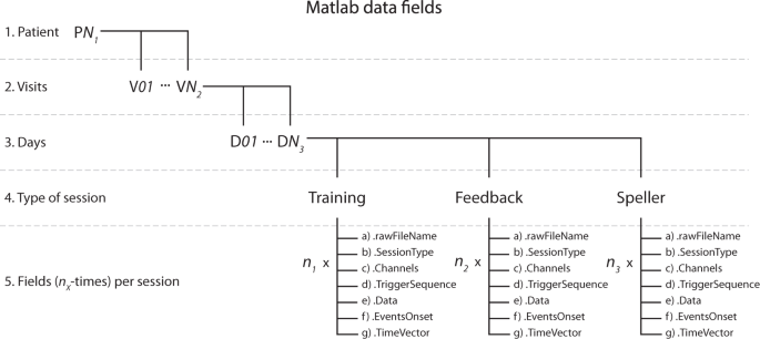
Matlab data fields structure. Nested structure elements containing the values and features of recordings from the study. According to the patient identifier, the upper level is the main structure, which can be PN1 = 11,13,15 or 16. In the next level, VN2 indicates the total number of visits available for that patient, and inside it, DN3 indicates the number of days that the visit lasted. Inside each day, there are structures for the Training and Feedback sessions and the spelling sessions (containing recordings from both the Copy and Free speller sessions). Each of these contains a set of structures that result from exporting the *.vhdr raw files for each recorded session, times the number of that particular session type (i.e., n1, n2, and n3) was performed during the day. Read the Data Records section for details on the data exporting.

Example of a Matlab structure of the data using P11’s data. The figure illustrates the data structure using P11’s data from visit V06 and day D03. (a) Indicates the selection of patient variables and the data fields corresponding to a particular visit and day and inside it, the type and number of sessions performed on the given day. (b) Depicts the presence of different fields upon selecting a session type, in this case, the number of Feedback sessions performed by P11, upon selection of Field named Feedback, and their different elements, as shown in the figure. Read the Data Records section for the detailed description.
At the 5th level, according to the type of session, there are seven fields stored, times the number of that particular session recorded on the day, i.e., n1, n2, and n3 (see Fig. 6). The hosted fields are:
-
(a)
.rawFileName: character type variable with the name of the original raw file that was exported
-
(b)
.SessionType: character type variable with the label of the type of session that the data belongs to
-
(c)
.Channels: cell array with 1xK dimensions, with K being the total number of EEG, EOG and EMG channels recorded, where each cell element is the label of a channel.
-
(d)
.TriggerSequence: cell array with 1xM dimensions, including the Mth events of all the trials recorded and the session as a sequence of triggers, with the labels indicated in Fig. 2., e,g., S 9, S 10, S 5, S 4, S 1, S 11, …, S 15
-
(e)
.Data: a KxR dimensional matrix of numerical values, being K the number of channels recorded, and R the number of data points in the time domain of the recording, each element being the amplitude values of the recording. It is highly relevant to consider that the default amplitude of the recording needs to be multiplied for a scaling factor of 0.0488281 (±410 mV range in 24 bits) to convert to µV21. The scaling factor can be verified inside every *.vhdr file produced for every recording
-
(f)
.EventsOnset; a 1xR dimensional vector of numerical values, being R the number of data points in the time domain of the recording, and to each time point we have assigned the numerical value of the trigger labels (see Fig. 2) occurring at that time point, e.g., 9, 10, 5, 4, 1, 11, …, 15, and a value of zero otherwise. This vector aims to help quickly locate each event’s onset and nature in the time domain
-
(g)
.TimeVector: a 1xR dimensional vector of numerical values, being R the number of data points in the time domain of the recording, where an element of R indicates the time value in seconds of the recording.
As an example of the previous variable description, Fig. 6 illustrates the data structure using P11’s data from visit V01 and day D03.
All the datasets described in this section can be freely downloaded from the open access repository22.
Technical Validation
The raw data referred to in this descriptor was recorded using a Brain Products V-Amp amplifier, without any type of hardware or software filter besides the physical instrumental restriction of the amplifier (wideband filter in the range of 0 Hz (DC) – 320 Hz or 4 kHz for the high-speed mode)21.
The raw data recorded with BrainVision Recorder software (v2.1.0) in *.ahdr, *.amrk, *.eeg formats were exported using BrainVision Analyzer software20 (v2.2.0) to obtain the formats19 *.vhdr, *.vmrk and *.eeg.
The data given as a Matlab format variable (*.mat) has been exported from the raw files taking advantage of the EEGLAB23 toolbox (https://sccn.ucsd.edu/eeglab/index.php, v2019.0) and the “bva-io” plugin (https://sccn.ucsd.edu/eeglab/plugin_uploader/plugin_list_all.php, v1.5.13), to save in the described variable structure desired features of the original raw file, as detailed in the Data Records section. No special parameter was used for exporting these data, and therefore we consider both raw and exported to the same values. Nevertheless, the amplitude of the recorded data (either.eeg or exported files using the “bva-io” plugin) is defined by the ADC bit resolution of the device, that is a ± 410 mV range in 24 bits, and therefore, the amplitude value needs to be multiplied by the scaling factor of 0.048828121 to be converted to µV (microvolts) units. The resolution of each recording can be found per channel inside each *.vhdr given file.
The Matlab script used to export the raw files to Matlab variables (see Code Availability section) includes a deactivated code line that can be used to convert to µV the amplitude.
EOG electrodes were located and placed according to the standard 10-20 system with EEG neoprene caps (Neuroelectrics, Barcelona, Spain), inserted in the cap using plastic holders. Once the whole set of electrodes was in place, they were filled with SuperVisc electrolyte gel (Easycap, Germany, GmbH). Impedance was measured on the whole set using an ImpBox (Brain Products, Germany, GmbH), to achieve a target impedance of 10 KΩ. Researchers in charge of the study ensured that the recorded activity had the proper impedance and a clean signal for all the channels. Recordings are not affected by muscular or blinking artifacts, besides eye movements related to the patients’ intentions.
Usage Notes
Performance of the communication system
The communication system can present a question every nine seconds with an information transfer rate of 6.7 bits/min. The system’s optimal speed can be improved depending on the speller scheme’s design for each individual patient and the corpus of sentences stored for word prediction. Descriptive statistics on each patient’s performance can be found in the related publication12.
A minimal criterion for communicating using the system is the presence of eye-movements recordable with sate of the art EOG recording devices in the microvolt range. For one of the patients, the progression of the disease over the course of a year eventually prevented him from controlling his oculomotor activity. He was however capable of producing undifferentiated EOG activity with low amplitude in the range of ±30 μV which reached that minimal criterion. The other patients never arrived at such a total loss of control when the data described here was recorded. Therefore, the duration of the transition period to CLIS, and whether voluntary communication with non-invasive physiological recording technologies, as described here, will be possible in CLIS, is still a matter of future research.
Date and time of the recordings
The original timestamp of the beginning of a recorded session can be found both inside the *.vhdr and the *.vmrk files, as the occurrence of the first marker in the recording. It can also be found as the timestamp of the sentence lists (Block_X_senlist.txt), or indicating the end of a session in the results text files (Date_result_f1_X.txt).
Name of the raw files
During the study, files recorded with BrainVision Recorder software (v2.1.0) (i.e., *.vhdr, *.vmrk and *.eeg) were labeled by the experimenters, and therefore, human error or discrepancies might have been committed during the labeling process. To clarify any possible confusion, the Online-only Tables 1–4 include a set of columns that show the correspondence between the name of the raw file, the session’s sequence, and any *.txt files attached to it.
The text lists (Block_X_senlist.txt and Date_result_f1_X.txt) were created automatically by a Matlab script running during each session.
From the given recordings, either raw or Matlab fields, it can be noticed from the labels that some files or sessions are lacking. This is because during the visits, sessions belonging to another paradigm for a different and unrelated study were also recorded, and they have been deliberately removed from the actual data descriptor to focus on the auditory communication recordings. Removed files are indicated in the Online-only Tables 1–4. Additionally, a number of files were lost or corrupted; the precise number and sessions are indicated in Table 1 and Online-only Tables 1–4.
EEG locations and inconsistency
Working with patients who have critical health conditions means being completely dependent on their current (minute by minute) state. These limitations were considered in the design of the study. The number of EEG electrodes was limited by restrictions of accessibility of some scalp regions. Since the patients lie on their backs most of the time, it is impossible to access occipital areas.
Nevertheless, the most relevant restriction is the time constraint, that is, to place a minimal number of EEG electrodes in appropriate locations, in the minimum possible time, so to maximize the time available to work with the patient before tiredness or another need (for example, sucking of saliva) prevents them from participating in the study. Consequently, the montages of electrodes might be affected by inconsistency in EEG electrode locations, even for the same patient, and different visits, since it is always dependent on changing circumstances of health and time.
Therefore, the criterion we follow aims to reach with the minimal number of electrodes the greatest coverage of the prefrontal and mesial surfaces of the brain (besides the EOG electrodes), under the assumption that the cognitive activity implicated in the processing of these questions might elicit changes in the electrical activity of the aforementioned cortical regions.
Regardless of that, we managed to keep a constant number of seven EEG electrodes and four EOG electrodes for most of the patients, for most of the visits, as can be verified in the Online-only Tables 1–4.
Audio files
The audio files (recorded questions) used in this research contains personal information of the patients and their relatives and consequently, to make these audio files fully open and public will compromise their identities. These data24 have been uploaded with restricted access, therefore any researcher or laboratory interested in accessing the data to perform the analysis will have to sign an identity protection agreement document provided as a “Data Use Agreement” Supplementary material with this manuscript.
Code availability
The given Matlab data variables were obtained by exporting the raw files (i.e., *.vhdr, *.vmrk, and *.eeg) using the EEGLAB23 toolbox (v2019.1.0) and exporting the data using the “bva-io” plugin (v1.5.13). We wrote a short Matlab script (ExportingCode_vhdr2mat.m) to export and save the desired features of the recordings, as thoroughly detailed in the section Data Records. The code is included in the same repository as the rest of the data, and it is accompanied by a brief document (ExportingCode_vhdr2mat.docx) explaining details of the code.
References
Birbaumer, N. & Chaudhary, U. Learning from brain control: clinical application of brain–computer interfaces. Neuroforum. 21(4), 87–96 (2015).
Birbaumer, N. Breaking the silence: Brain–computer interfaces (BCI) for communication and motor control. Psychophysiology. 43, 517–532 (2006).
Chaudhary, U., Birbaumer, N. & Ramos-Murguialday, A. Brain-computer interfaces for communication and rehabilitation. Nat. Rev. Neurol. 12, 513–525 (2016).
Brownlee, A. & Bruening, L. M. Methods of communication at end of life for the person with amyotrophic lateral sclerosis. Top. Lang. Disord. 32(2), 168–185 (2012).
Bauer, G., Gerstenbrand, F. & Rumpl, E. Varieties of the locked-in syndrome. J. Neurol. 221, 77–91 (1979).
Kübler, A. & Birbaumer, N. Brain-computer interfaces and communication in paralysis: Extinction of goal directed thinking in completely paralyzed patients? Clin. Neurophysiol. 119, 2658–2666 (2008).
Calvo A. et al. In International Conference on Computers for Handicapped Persons 2008, vol 5105 (eds. Miesenberger K., Klaus J., Zagler W., Karshmer A.) pp 70-77 (Springer, Berlin, Heidelberg, 2008).
Beukelman, D., Fager, S. & Nordness, A. Communication Support for People with ALS. Neur. Res. Int 04, 714693 (2011).
Chaudhary, U., Birbaumer, N. & Ramos-Murguialday, A. Brain-computer interfaces in the completely locked-in state and chronic stroke. Prog. Brain Res 228, 131–61 (2016).
Chaudhary, U., Birbaumer, N. & Curado, M. R. Brain-machine interface (BMI) in paralysis. Annals of Physical and Rehabilitation Medicine 58(1), 9–13 (2015).
Chaudhary, U., Mrachacz‐Kersting, N. & Birbaumer, N. Neuropsychological and neurophysiological aspects of brain‐computer‐interface (BCI)‐control in paralysis. J. Physiol. 00.0, 1–9 (2020).
Tonin, A. & Jaramillo-Gonzalez, A. et al. Auditory Electrooculogram-based Communication System for ALS Patients in Transition from Locked-in to Complete Locked-in State. Sci. Rep. 10, 1 (2020).
Gorges, M. et al. Eye movement deficits are consistent with a staging model of pTDP-43 pathology in Amyotrophic Lateral Sclerosis. PLoS One 10(11), e0142546 (2015).
BNCI Horizon 2020 http://bnci-horizon-2020.eu/database (2020).
PhysioNet: The research resource for complex physiological signals https://physionet.org/about/database/ (2020).
BrainSignals: Publicly available brain signals EEG MEG ECoG data http://www.brainsignals.de/ (2020).
Cedarbaum, J. M. et al. The ALSFRS-R: a revised ALS functional rating scale that incorporates assessments of respiratory function. J. Neurol. Sci. 169, 1–2 (1999).
Brain Products GmbH. BrainVision Recorder User Manual https://www.brainproducts.com/downloads.php?kid=2 (2019).
Brain Products GmbH. Description of the BrainVision Core Data Format 1.0 https://www.brainproducts.com/files/public/products/more/BrainVisionCoreDataFormat_1-0.pdf (2019).
Brain Products GmbH. BrainVision Analyzer 2.0 User Manual https://www.brainproducts.com/downloads.php?kid=9 (2019).
Brain Products GmbH. V-Amp & ImpBox Operating Instructions, 7th Version https://www.brainproducts.com/files/secure/Manuals/V-Amp_OI.pdf (2016).
Jaramillo-Gonzalez, A. et al. A Dataset of EEG and EOG recordings from an Auditory EOG-based Communication System for Patients in Locked-In State. Zenodo https://doi.org/10.5281/zenodo.4002038 (2020).
Delorme, A. & Makeig, S. EEGLAB: an open source toolbox for analysis of single-trial EEG dynamics including independent component analysis. J. Neurosci. Methods. 134(1), 9–21 (2004).
Jaramillo-Gonzalez, A. et al. Audio files for A Dataset of EEG and EOG recordings from an Auditory EOG-based Communication System for Patients in Locked-In State. Zenodo https://doi.org/10.5281/zenodo.4286416 (2020).
Acknowledgements
Deutsche Forschungsgemeinschaft (DFG) DFG BI 195/77-1, BMBF (German Ministry of Education and Research) 16SV7701 CoMiCon, and LUMINOUS-H2020-FETOPEN-2014-2015-RIA (686764).
Author information
Authors and Affiliations
Contributions
Andres Jaramillo-Gonzalez – Performed 35% of the Auditory communication system (ACS) sessions and data collection; Data curation; Manuscript writing. Shihze Wu – Data curation and validation. Alessandro Tonin – Performed 35% of the ACS sessions and data collection. Aygul Rana – Performed 35% of the ACS sessions and data collection. Majid Khalili Ardali – Discussion in Laboratory. Niels Birbaumer – Study design and conceptualization; Manuscript correction. Ujwal Chaudhary – Study design and conceptualization; Performed 65% of the ACS sessions and data collection; Supervision; Manuscript writing.
Corresponding author
Ethics declarations
Competing interests
The authors declare no competing interests.
Additional information
Publisher’s note Springer Nature remains neutral with regard to jurisdictional claims in published maps and institutional affiliations.
Supplementary information
Online-only Tables
Rights and permissions
Open Access This article is licensed under a Creative Commons Attribution 4.0 International License, which permits use, sharing, adaptation, distribution and reproduction in any medium or format, as long as you give appropriate credit to the original author(s) and the source, provide a link to the Creative Commons license, and indicate if changes were made. The images or other third party material in this article are included in the article’s Creative Commons license, unless indicated otherwise in a credit line to the material. If material is not included in the article’s Creative Commons license and your intended use is not permitted by statutory regulation or exceeds the permitted use, you will need to obtain permission directly from the copyright holder. To view a copy of this license, visit http://creativecommons.org/licenses/by/4.0/.
The Creative Commons Public Domain Dedication waiver http://creativecommons.org/publicdomain/zero/1.0/ applies to the metadata files associated with this article.
About this article

Cite this article
Jaramillo-Gonzalez, A., Wu, S., Tonin, A. et al. A dataset of EEG and EOG from an auditory EOG-based communication system for patients in locked-in state. Sci Data 8, 8 (2021). https://doi.org/10.1038/s41597-020-00789-4
Received:
Accepted:
Published:
DOI: https://doi.org/10.1038/s41597-020-00789-4
- Springer Nature Limited