
Abstract
To protect the security of data outsourced to the cloud, the tampers detection and recovery for outsourced image have aroused the concern of people. A secure tampering detection and lossless recovery for medical images (MI) using permutation ordered binary (POB) number system is proposed. In the proposed scheme, the region of interest (ROI) of MI is first extracted, and then, ROI is divided into some no-overlapping blocks, and image encoding is conducted on these blocks based on the better compression performance of JPEG-LS for medical image. After that, the generated compression data by all the blocks are divided into high 4-bit and low 4-bit planes, and shuffling and combination are used to generate two plane images. Owing to the substantial redundancies space in the compressed data, the data of each plane are spread to the size of the original image. Lastly, authentication data of two bits is obtained for every pixel and inserted into the pixel itself within the each plane, and the corresponding 10-bit data is transformed into the POB value of 8-bit. Furthermore, encryption is implemented on the above image to produce two shares which can be outsourced to the cloud server. The users can detect tampered part and recover original image when they down load the shares from the cloud. Extensive experiments on some ordinary medical image and COVID-19 image datasets show that the proposed approach can locate the tampered parts within the MI, and the original MI can be recovered without any loss even if one of the shares are totally destroyed, or two shares are tampered at the ration not more than 50%. Some comparisons and analysis are given to show the better performance of the scheme.
1 Introduction
With the rapid development of network and communication, a large of number of image data are produced and outsourced to the cloud. As the cloud is regarded as dishonest entity, the privacy protection of outsourced image has drawn much attention from researchers, and many schemes have been proposed to solve the problem. In general, there are two approaches to protect privacy of the outsourced image; one is to conduct encryption of image before it is outsourced to the cloud [1,2,3], the other one is to utilize the combination of encryption and digital watermarking to protect images [4,5,6].
As one kind of important image types, the protection of medical image has its particularity; it demands that when the medical image is recovered from its encrypted or watermarked form, the original image should be restored without any loss, as it has vital influence to medical diagnosis if there are some tampers in the original image, based on these demands, people have pay much more attention to the location and lossless recovery of tampers of original image, and many schemes have been presented [7,8,9,10,11,12,13,14,15,16,17,18]. For example, an improved tampering localization and self-recovery scheme based on fragile watermarking is presented by Sergio Bravo-Solorio, et al. [7], here, they use a secure block-wise mechanism to locate distorted blocks of pixels, and the tampering position accuracy is refined by means of an iterative pixel-wise mechanism, which estimates the original watermarked pixels in altered regions. Afterwards, due to the good performance of compressed representation of Vector Quantization (VQ) and the automatic recovery capability of image inpainting, a new scheme is proposed to implement adaptive self-recovery for tampered digital images based on the two characteristics [8]. In order to provide detection and recovery rate for tampers, a method based on singular value decomposition of the image blocks is proposed for digital image tamper localization and self-recovery, better performance is achieved [9]. Afterwards, a discrete cosine transform (DCT) based self-recoverable fragile watermarking scheme is presented, in this scheme, two authentication bits and ten recovery bits within the block are embedded in the three least significant bits (LSBs) of the block itself while recovery bits are embedded in the three LSBs of the corresponding mapped block [10]. In the meantime, they presented a self-embedding fragile watermarking scheme with effective image authentication and restoration based on a quantization and DCT [11]. In the scheme proposed by Sreenivas et al., the 4 bits authentication of \(2 \times 2{ }\) image block and restoration bits are embedded into the randomly selected distinct blocks by the help of chaos, and the better performance in tampers detection and the recovery under extensive tampering is achieved [12]. In recent years, Gao et al. presented a reversible data hiding algorithm for medical images, the scheme achieved contrast enhancement of the region of interest (ROI), and in the meantime, it can locate the position of the tampers against attacks on the ROI [13]. Tai et al. presented a tampers detection and recovery scheme, in their approach, the fragile watermark of one block which consists of authentication data and recovery data are embedded into the other block according to the embedding sequence generated by chaotic map, and in the meantime, to reduce the smoothing blocking effect of recovered images, the wavelet transform are used to enhance the image contrast [14]. Not long after, a fragile and blind dual watermarking method for tamper detection and self-recovery based on the lifting wavelet and the halftoning technique is presented, and better performance was achieved [15]. Singh et al. proposed a self-embedding fragile watermarking technique based on quantization, and block truncation coding (BTC), and even if tempering rate is 50%, the reconstructed image has high peak signal-to-noise ratio (PSNR) [16]. Based on improved joint source-channel coding optimizer, Gu et al. gave a new image self-recovery scheme; the algorithm performs quadtree decomposition of original grayscale image corresponding to different decomposition factors and performs bit-plane layering according to the block class obtained by quadtree decomposition, and achieved high quality of restored image [17]. And recently, a authentication and self-recovery for color image is presented in [18], the novelty lie in that bilateral filter that efficiently suppresses noise preserving image edges is used in the image post-processing.
Although better performances of image tampers location and recovery have been obtained in the above schemes, one defect for most of them is that they can’t recovery the original image without any loss with the tampers happened. Therefore, some schemes using secret shares are proposed to solve the problem. Among them, an image sharing scheme that allows the user to retrieve a scaled or cropped version of the secret image by operating directly on the shadow images is presented in [19], and a secured image data sharing scheme over cloud domain based on the Shamir's secret sharing and permutation ordered binary number system is presented in [20]. After that, permutation ordered binary (POB) number system and Chinese remainder theorem (CRT) are used to generate multiple secret shares, and it has better performance for image reconstruction [21]. Recently, tampers detection and recovery using POB aroused the attention of researchers; for example, Singh et al. proposed an image tampering detection and localization using POB number system, the scheme can accurately identify the altered pixels via authentication bits and localizes the tampered area, the tampered portion is also reflected back in the reconstructed image that is obtained [22]. Then, they presented an approach to detect and accurately recover tampered regions of video at the pixel level in the encrypted domain, the efficacy of the scheme has been validated by testing against various attack scenarios [23, 24]. Xiang et al. proposed a secure image tampering detection and self-recovery scheme based on POB and singular value decomposition (SVD), the scheme used authentication for tampers detection and recovery watermarking for recovery of tampers [25]. After that, Liu et al. gave a lossless image hierarchical recovery based on POB number system; the scheme contains a two-level comparison, neighbor-based refinement and watermark-based refinement in the stage of image recovery [26]. Recently, You et al. suggested a lossless self-recovery watermarking scheme with JPEG-LS compression scheme, the scheme implements JPEG-LS on ROI, and then embeds the compressed data in to the whole image, test results on medical images show the effectiveness of the proposed scheme.
It can be seen from the above secret shares based schemes that, most of them can’t achieve totally reversibility for the recovered image with the shares tampered. To overcome this problem, a secure lossless tampers detection and recovery approach for medical image (MI) is proposed; the proposed scheme utilizes the better compression performance of JPEG-LS and POB system, and achieves the totally reversible recovery of tampers even two shares are tampered with size not more than 50%. Some comparisons and analysis are given to testify the proposed scheme. The main contributions of this work are summarized as follows:
-
Using JPEG-LS and the POB system, a lossless recovery and tamper detection approach for the original medical image is proposed.
-
Utilizing the rich redundant features of data generated by the JPEG-LS, the proposed scheme achieves the strong robustness against tampers of the shares. The original image can be restored without any loss even if one of the shares is totally tampered or both shares are tampered with the size less than 50%.
-
Extensive experiments on medical images, including COVID-19 images show the better performance of tampers detection for the proposed scheme.
The rest sections of this paper are organized as follows: In Sect. 2, some the preliminaries related to the proposed scheme are described. The detailed description of the proposed scheme and experimental results analysis are discussed in Sect. 3. Finally, some conclusions are drawn in Sect. 4.
2 Preliminaries
In this section, some preliminaries such as JPEG-LS-based image encoding and POB number system are first introduced, and some notations used in this paper are summarized in Table 1.
2.1 JPEG-LS-based image coding
JPEG-LS is a lossless or near lossless compression standard for continuous-tone image proposed by the International Standards Organization ISO/IEC JTC1 [28, 29], it is based on the LOCO-I algorithm (low complexity lossless compression for images) which depends on a pixel prediction based contextual statistical model [30]. It has been widely used for image compression and image security [31, 32].
2.2 POB number system
The POB number system is proposed by Sreekumar and Sundar [33]. The system is denoted by POB (n, r), where n and r are non-negative integral parameters such that \({\text{n}} \ge {\text{r}}\). In this number system, all the integers are in the range 0, 1, \(\left( {\begin{array}{*{20}c} n \\ r \\ \end{array} } \right) - 1\), a binary string with r 1 s can be expressed by \({\text{B}} = b_{n - 1} b_{n - 2} \cdots b_{0}\). Then, the value of the POB-number B is calculated by following formula
where, \(p_{j} = \mathop \sum \limits_{i = 0}^{j} b_{i}\). It can be proved that, every such POB-number,\({\text{B}} = b_{n - 1} b_{n - 2} \cdots b_{0}\), there exists a distinct representation of POB value.
For example, POB value of the binary string with10-bit 1,001,101,010 can be calculated by Eq. (1).
\(\begin{gathered} {\text{V}}\left( {\text{B}} \right) = b_{0} \times \left( {\begin{array}{*{20}c} 0 \\ 0 \\ \end{array} } \right) + b_{1} \times \left( {\begin{array}{*{20}c} 1 \\ 1 \\ \end{array} } \right) + b_{2} \times \left( {\begin{array}{*{20}c} 2 \\ 1 \\ \end{array} } \right) + b_{3} \times \left( {\begin{array}{*{20}c} 3 \\ 2 \\ \end{array} } \right) + b_{4} \times \left( {\begin{array}{*{20}c} 4 \\ 2 \\ \end{array} } \right) + b_{5} \times \left( {\begin{array}{*{20}c} 5 \\ 3 \\ \end{array} } \right) + b_{6} \times \left( {\begin{array}{*{20}c} 6 \\ 4 \\ \end{array} } \right) + b_{7} \times \left( {\begin{array}{*{20}c} 7 \\ 4 \\ \end{array} } \right) + b_{8} \times \left( {\begin{array}{*{20}c} 8 \\ 4 \\ \end{array} } \right) + b_{9} \left( {\begin{array}{*{20}c} 9 \\ 5 \\ \end{array} } \right) \hfill \\ \,\,\,\,\,\,\,\,\,\,\,\,\, = 0 \times 1 + 1 \times 1 + 0 \times 2 + 1 \times 3 + 0 \times 6 + 1 \times 10 + 1 \times 15 + 0 \times 35 + 0 \times 70 + 1 \times 126 \hfill \\ { }\,\,\,\,\,\, = 155 \hfill \\ \end{gathered}\) At present, several schemes have been proposed to show POB based method has better application in secret sharing and recovery of tampered regions in image [21,22,23,24].
2.3 Image shuffling
The aim of image shuffling is to strengthen the security of the proposed scheme. It can be expressed by formula (2)
where, \(I{ }\) is the original data which may consists of n numbers to be shuffled, \(Key \) is the secret key used for generating \(new\_index\) for shuffling, and the index is index sequences of pixel in the original I, while \(I_{shuf}\) is the shuffled I, and \(new\_index\) is the new index sequences of numbers in original I produced by nonlinear mapping function \(\Phi\). In the proposed scheme, nonlinear mapping \(\Phi\) is given by Logistic chaos mapping (LCM):
where, the initial value \(x_{0 }\) of LCM is used as the secret Key, which is not equal 0.5.
For example, the original image is assumed to be given by matrix A or transformed sequence B from A in column sequence.
The initial value of LCM is given by \(x_{0}^{\left( 1 \right)} = 0. 0.003096800078798\), the produced sequence by iterating LCM is as followings:
Then, x is sorted by ascending order and the new sequence and new index are generated:
The new generated index sequence is \(index_{new} = \left\{ {1, 2, 9, 6, 3, 7, 4, 5, 8} \right\}\) the matrix A is rearranged according to the new generated index which is depicted in Fig. 1.

Example of image shuffling
3 The proposed scheme
In this section, the detailed flowchart of the proposed scheme is first presented, and then, every procedure in the process will be described in detail. After that, some experimental results, analyses, comparisons and discussions are given to show the effectiveness of test for the proposed scheme. The overall flowchart of the proposed scheme is shown in Fig. 2.

The overall flowchart of the proposed scheme
3.1 Generation of shares
In order to generate the shares which are outsourced to the cloud, the original medical image need to be processed by several steps, and we will discuss these procedures in the followings.
3.1.1 Encoding image
In the proposed scheme, the ROI is first extracted automatically or by hand from the original medical image. After that, ROI is divided into some no-overlapping blocks with the size of 8 × 8, and then JPEG-LS is used to encode every image block of ROI. All the compressed data of every block are combined into the compressed information which is denoted as Iced. Then, the corresponding sequence number should be:
3.1.2 Bit-plane separation
In this section, bit-plane will be conducted for the compressed image data \(I_{ced}\), the detailed descriptions of separation into two images are presented in the following steps:
-
(1)
Extract the high 4-bit for every number in the \(I_{ced}\), and call it \(high_{{\text{p }}}\), and in the meantime, the low 4-bit of the data is also extracted, and it is labeled as \(low_{{\text{p}}}\).
-
(2)
Shuffle the \(high_{{\text{p }}}\) with the key \(k_{h }\) and \(low_{{\text{p}}}\) with the key \(k_{l }\), respectively. The shuffled data in high-level plane image is labeled as \(high_{{{\text{sp}}}}\), and the shuffled data for low 4-bit is labeled as \(low_{{{\text{sp}}}}\).
-
(3)
Generate high-level plane of 8-bit. In this processing, the 8-bit high-level plane image is produced by \({ }high_{{\text{p }}} = 16 \times low_{{{\text{sp}}}} + high_{{\text{p }}}\).
-
(4)
Generate low-level plane image of 8-bit by \({ }low_{{\text{p }}} = 16 \times high_{{{\text{sp}}}} + low_{{\text{p}}}\).
Thus, the two bit plane images are produced through the above steps. The flowchart for the generation of high-level plane and low-level plane can be shown in Fig. 3.

The generation of high-level plane image and low-level plane image. a The generation of high-level plane image. b The generation of low-level plane image
3.1.3 The generation and self-embedding of authentication data
In this stage, for the above generated bit-plane images \({ }high_{{\text{p}}}\) and \({ }low_{{\text{p}}}\), for every data, one 2-bit authentication data will be produced and embedded into the bit plane image data itself. The procedure is described by the following methods.
For the given data a in \({ }high_{{\text{p}}}\), assume it is expressed by \(b_{7} b_{6} b_{5} b_{4} b_{3} b_{2} b_{1} b_{0}\), where \(b_{j} ,j = 0,1, \cdots ,7\) is 0 or 1. If the number of 1 within \(b_{7} b_{6} b_{5} b_{4}\) is odd, the first bit is set to be 1; else it is set to be 0. In the same way, the second bit is set to be 1 if and only if the number of 1 within \(b_{3} b_{2} b_{1} b_{0 }\) is odd.
In this way, 2-bit data is generated by a, and then it is appended at the end of data a, thus, the data turns to become 10-bit data. In order to easily and conveniently process the image, every data with 10-bit will be transformed into the corresponding decimal value of POB number with the size of 8-bit using formula (1). An example is illustrated in Fig. 4.

The example for authentication embedding and transformation
In the same way, the authentication data in \(low_{{\text{p}}}\) can be obtained and embedded in the data itself, and finally it is transformed into the POB value with size of 8-bit. The detailed description on the generation and self-embedding of authentication can be shown in Fig. 5.

The generation of authenticaition data and embedding
After this procedure, two images with embedded authentication data are generated, they are labelled as \(high_{{\text{e}}}\) and \(low_{{\text{e}}}\), respectively.
3.1.4 Spreading of two level data and encryption
Here, for the above generated bit plane images which are self-embedded by authentication data, we will spread image data into the same size as that of the original image. As the compressed data is shorter than the original image, some data in \(high_{{\text{e}}} \) or \(low_{{\text{e}}} \) may appear several times in the spreading image.
Figure 6 give an illustration on the spreading of compressed data. In order to produce the same length of data as that of the original image, the compressed data need to be put several times to achieve the same size as that of the original image.

The sketch map of spreading of compressed data
For example, the original medical image IM-0001-0012 shown in Fig. 7a is with the size of \(512 \times 512\), there are total 262,144 pixels. For the ROI shown in Fig. 7b, after compression, the number of data in high level plane is 65833, thus, every data in generated bit plane image \(high_{{\text{e}}} \) may emerge \({\raise0.7ex\hbox{${262144}$} \!\mathord{\left/ {\vphantom {{262144} {65833}}}\right.\kern-\nulldelimiterspace} \!\lower0.7ex\hbox{${65833}$}} = 3.98\) times when they are spread into the size of \(512 \times 512\). In the same way, there are 84,598 data in the generated bit plane image generated from Fig. 7d which is the ROI of Fig. 7c, thus, when the data are spread to the size of \(512 \times 512\), every data may appear floor(\({\raise0.7ex\hbox{${262144}$} \!\mathord{\left/ {\vphantom {{262144} {84598}}}\right.\kern-\nulldelimiterspace} \!\lower0.7ex\hbox{${84598}$}}) =\) 3.09 times.

Some typical test images used for experiments
Lastly, for the safety, the two bit plane images after spreading are encrypted by hyper-chaos based encryption algorithm [34]. It should be mentioned that, in this stage, we can use any kind of secure encryption algorithm. Thus, two shares are produced; they can be outsourced to the same cloud server or different cloud server.
3.2 Tamper detection and cover image recovery
When the users of the medical image download the shares from the cloud serer, they can use the following steps to verify the integrity of the medical image and recover the original secret image.
-
(1)
For the two shares \({ }high_{{\text{es }}}\) and \({ }low_{{\text{es }}}\), they are firstly decrypt by the same secret key as that used in encryption process, and two shares \({ }high_{{\text{s }}}\) and \( low_{{\text{s }}}\) are got.
-
(2)
Convert \({ }high_{{\text{s }}}\) and \( low_{{\text{s }}}\) into the POB numbers with 10-bit by Algorithm 2 shown in Fig. 8. The returned image is 10-bit data.

Description of the algorithm 2
-
(3)
For the image \({ }high_{{\text{s }}}\), the last two bits data from every 10-bit data are extracted. Thus, one can calculate the number of 1 with the high 4-bit and that of the low 4-bit except for the two least significant bits for every data, thus two groups data of 2-bit data are obtained, respectively. One can judge whether the pixel value is tampered or not through comparing the obtained two group’s data. The same operation can also be performed on \(low_{{\text{s }}}\).
After removing the last two authentication bits, high bit plane image \({ }high_{{\text{p }}}\) and low bit plane image \({ }low_{{\text{p }}}\) are derived.
-
(4)
Recovery of the original image
For the obtained high bit plane image \({ }high_{{\text{p }}}\), we separate it into high 4-bit and low 4-bit plane, called \(high_{{\text{hbitp }}}\) and \({ }high_{{\text{lbitp }}}\), and then reshuffle the \({ }high_{{\text{hbitp }}} \) to get \({ }high_{{\text{shbitp }}}\) using the same key \(k_{h }\) as that used in original shuffling. After that, the compressed data can be restored by formula (4).
$$ Compressed data_{h} = 16 \times high_{{{\text{lbitp}}}} + { }high_{{\text{shbitp }}} $$(4)Lastly, the compressed data \(Compressed data_{h} \) are decoded using JPEG-LS block by block to restore the original ROI, and the original image can be losslessly recovered.
In the same way, the original image can also be recovered through \({ }low_{{\text{p }}}\). Low bit plane image \({ }low_{{\text{p }}}\) is separated into high 4-bit and low 4-bit plane, called \({ }low_{{\text{hbitp }}}\) and \({ }low_{{\text{lbitp }}}\), and then reshuffle the \({ }low_{{\text{hbitp }}} \) to get \({ }low_{{\text{shbitp }}}\) using the same key \(k_{l }\) as that used in original shuffling. After that, the compressed data can be restored by formula (5).
$$ Compressed data_{l} = 16 \times low_{{{\text{shbitp}}}} + { }low_{{\text{lbitp }}} $$(5)The generated \(Compressed data_{l}\) then are decoded by JPEG-LS block by block to restore the original ROI, and thus the original image can be losslessly recovered.
-
(5)
Tamper detection
For the two shares which are outsourced to the cloud, once one or two shares are tampered, users who want to use the image must be able to know whether the two shares have been tampered or original image can be restored or not. Thus, the following sections will describe how the tampered blocks are detected and how the original image is recovered.
As the compressed data are spread over the entire share, some data may be the same in different locations. Thus, in order to get the real compressed data, these data in different positions need to be judged and compared, the refinement processes of extracting and detection compressed data from \(high_{p}\) are described in the followings.
-
(1)
For the obtained high bit plane image \({ }high_{{\text{p }}}\) and low bit plane image \({ }low_{{\text{p }}}\) with the 10 bits data, The number k of occurrences of each data is firstly calculated, thus there are k groups identical compressed data in \({ }high_{{\text{p }}}\).
-
(2)
Assume that the length of compressed data is L, for the data in one group of \({ }high_{{\text{p }}}\), calculate the 2 bits authentication data and extract last 2-bit data, if these two 2 bits data are not equal, repeat conducting the same operation for the same data in the next group; If the extracted 2 bits data and 2 bits authentication data within all the groups are not equal, the data detection result is set to 1 in this position; else the detection result is set to be 0, and the extracted data in \({ }high_{{\text{p }}}\) is saved. In this way, the data without being tampered for compressed data are extracted, only data in all the groups are tampered, it is regarded as a tampered one. The detailed descriptions of detection and extraction are given by Algorithm 3 shown in Fig. 9. It can be seen that the core of the Algorithm 3 is to obtain the real compressed data, as there are several copies for every compressed data; we only select the one which is not tampered as the real one. For every compressed data, its detection result is kept in Detect_H, where, the value 0 means the compressed data is real; else it means the compressed data is tampered.
Fig. 9 
Description of the algorithm 3
The compressed data and detection results from the \( Low_{p}\) with 10-bit can also be obtained by the same way as that used in Algorithm 3; they are denoted by CompressedDL and Detect_L, respectively.
-
(1)

-
(6)
Data refinement between the compressed data produced by two bit plane images
After two groups compressed data are derived from \( Low_{p} \) and \( High_{p}\), the data refinement between these two groups of data must be conducted to obtain real and effective compressed data.
Firstly, for the share CompressedDH, it is first separated into two 4-bit plane data, and then the high 4-bit plane and the Detect_H are reshuffled using the same secret key as that used in the process of generation of shares. Then for every data, we compare the value of Detect_H and shuffled Detect_H, if they are equal to zero, then this data is considered to be intact, else it is regarded as tampered.
In the same way, for the CompressedDL and Detect_L, the same method can be used to derive real and effective data from the \( Low_{p}\). The process flowcharts are shown in Fig. 10.
Fig. 10 
The flowchart of recovery for the compressed data (a). Recovery of compressed data from high bit plane image (b). Recovery of compressed data from low bit plane image
Lastly, we should compare detection results of Detect_L and Detect_H, the compressed data is regarded as intact if and only if some one of the value in Detect_L and Detect_H is 0, and the recovered compressed data is replaced with the corresponding detection result.
Lastly, the original ROI can be restored by JPEG-LS decoding block by block without any loss.

4 Experimental results and analysis
In this section, a large numbers of experiments for the proposed scheme are implemented, the images used for test are download from some open dataset with the size of \(512 \times 512\). Some typical images are shown in Fig. 11. In the meantime, some comparisons on embedding rate (bpp), visual quality of the final recovered image are given to testify the proposed scheme.

The images used for test
4.1 Security analysis
-
(1)
Key space analysis
It can be seen from the description of the proposed scheme, the generation of anyone share is relevant to the shuffling algorithm, and the key space for shuffling is \(10^{14}\). In the meantime, from the definition of POB number system, a specific POB number with 10-bit can be represented in the range of \(\left[ {0,\left( {\begin{array}{*{20}c} n \\ r \\ \end{array} } \right) - 1} \right]\), here, r is the number of 1 s, and n is 10. Obviously, if r is set to be 4, POB number has 210 possibilities, thus, for image with size of \({\text{N}} \times {\text{M}}\), the successful probability of guessing the share is \(\left( {{\raise0.7ex\hbox{$1$} \!\mathord{\left/ {\vphantom {1 {210}}}\right.\kern-\nulldelimiterspace} \!\lower0.7ex\hbox{${210}$}}} \right)^{M \times N}\). Lastly, the key space used for encryption is \(2^{128}\), so the proposed scheme can effectively resist brute attack.
On the other hand, different from the scheme [22, 25] which generate shares by POB number system in the last step of the scheme, in the last step of our scheme, we implement encryption of the shares generated by POB, this is because that shares generated by POB has some kind of statistics features that may arouse the curiosity of attackers.
For example, histogram of image can embody the statistics feature of pixel distribution, Fig. 12a is an original medical image, the histogram of one share generated by our scheme is shown in Fig. 12b, however, Fig. 12c is the histogram generated by reference [26]. Obviously, there is no any visual statistics feature to be observed in Fig. 12b, however, the feature of Fig. 12c can cause suspicions of others.
Fig. 12 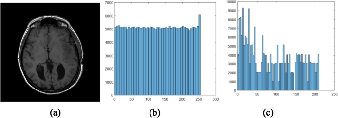
The image and comparison of histograms with other method
-
(2)
Image entropy
Information entropy can be used to find the unpredictability and randomness, and the ideal value for random image for which the pixel values always fall in the range of 0–255 is always equal to 8. The entropy of image is given by formula (8) according to Shannon’s communication theory of secrecy systems.
$$ {\text{H}} = - \sum p_{i} log p_{i} $$(6)where \( p_{i} \) is the probability of the pixel values in the image and summation is taken over all possible pixel values. It has been shown that the entropy of a pure random noise image should be equal to 8, and the entropy is 7.7706 in the case of 2-bit authentication [25].
In the proposed scheme, the entropy of share is 7.9992; hence, it is almost equivalent to a random image. If we first encrypt the bit plane image, and then embed the authentication data, the entropy is 7.21872.

-
(3)
The correlation coefficients
The correlation coefficients between adjacent pixels reflect the image feature, the smaller correlation coefficients of encrypted image mean that the encrypted image looks like noise image, it can be calculated as follows:
$$ r = \frac{{\sum\limits_{i = 1}^{N} {\left( {x_{i} - \overline{x} } \right)} \left( {y_{i} - \overline{y} } \right)}}{{\sqrt {\left( {\sum\limits_{i = 1}^{N} {\left( {x_{i} - \overline{x} } \right)} } \right)^{2} \left( {\sum\limits_{i = 1}^{N} {\left( {y_{i} - \overline{y} } \right)} } \right)^{2} } }} $$(7)where, \({\text{x}}_{{\text{i}}}\) and \({\text{y}}_{{\text{i}}}\) here are the values of the adjacent pixels, \(\overline{x}\) and \({\overline{\text{y}}}\) are the means of them, \({\text{N}}\) is the number of the adjacent pixels.
For the proposed scheme, the correlation coefficients in vertical, horizontal and diagonal direction are 0.01137, 0.0162, and 0.0044, respectively.
-
(4)
The number of changing pixel rate (NPCR) and the unified averaged changed intensity (UACI)
NPCR and UACI are two common quantities used to evaluate the strength of image encryption algorithms with respect to differential attacks. They signify the chance of occurrence of the attack and its sensitivity towards the source image by changing the value. They are given by Eqs. (8) and (9), respectively.
$$ NPCR = \frac{{\mathop \sum \nolimits_{i = 1}^{N} d_{i} }}{N} \times 100 $$(8)$$ d_{i} = \left\{ {\begin{array}{*{20}c} {\begin{array}{*{20}c} 1 & {I\left( i \right) \ne I^{\prime}\left( i \right)} \\ \end{array} } \\ {\begin{array}{*{20}c} 0 & {I\left( i \right) = I^{\prime}\left( i \right)} \\ \end{array} } \\ \end{array} } \right. i = 1,2, \cdots N $$$$ UACI = \frac{1}{N}\mathop \sum \limits_{i = 1}^{N} \frac{{\left| {(I\left( i \right) - I^{\prime}\left( i \right)} \right|}}{255} $$(9)For the proposed scheme, the NPCR is 99.6033 and the UACI is 33.4599, this means that the proposed method can well resist the known-plaintext and chosen-plaintext attacks.
It is obvious; the above test results show that the proposed scheme can effectively resist brute force attack as it has large space of secret key. And moreover, it can also resist attack coming from statistical feature of the shares.
4.2 Tampering localization and image recovery
Firstly, the medical image IM-0001-0012 is used for various tests. In the experiments, if there is no any tampering in the two shares, the original ROI can be totally recovered without any loss. The original image, ROI, generated two shares and the recovered ROI are shown in Fig. 13.

The experimental results. a Original image. b Extracted ROI. c and d shares. e Restored image
Next, some attack tests on shares are conducted. The attacks by text addition, content removal and content exchange on one share are shown in Fig. 14a–c. For the content removal attack, a block with size of \(287 \times 283\) from the left corner point \(\left( {95,125} \right)\) is cropped within the share. For the content exchange, a block with size of \(312 \times 321\) from the left corner \(104 \times 110\) is replaced by other contents. In this case, only one share is tampered, and the detection results of the first round are shown in Fig. 14d–f, and that of the second round are shown in Fig. 14g–i, the lastly refined detection results are shown in Fig. 14j–l. It has been shown that the finally restored ROI is the same as the original one. The original image can be losslessly recovered.

The test results against some attacks on the share. a Text addition attack. b Content removal attack. c Content replacement attack; d–f the detection results of the first round; g–i are the the detection results of the second round; j–l are the losslessly recoverd image
Furthermore, from the depiction of the proposed scheme, even if anyone of the two shares is totally tampered, the original image can be recovered without any loss; in the meantime, when one share is tampered with the size of less than 50%, whether what is the tampered size in the other share, the original image can be recovered without any loss. The experiment results are summarized in Table 2.
Next, some tests are given to verify the recovery performance of the proposed scheme with the two shares tampered. In the experiments, some contents removal attacks are given, and the test results are shown in Fig. 15. Where, Fig. 15a and b are tampered shares, and one-fourth of the share is tampered for every share, the recovered images by the algorithm [26] are given by Fig. 15c and d shows the totally recovered images by the proposed scheme. It can be seen that the proposed scheme has great improvement than reference [26] with the two shares tampered.

The test results with the two shares tampered. a Attack on the first share; b Attack on the second share; c Recovery results by reference [26]; d The losslessly recovered image by the proposed scheme
Lastly, some tests with no regular tampers in the shares are presented. The experimental results are displayed in Fig. 16. Where, Fig. 16a is the original ROI, Fig. 16b and c are tampered shares with fifty percent of the size in one share, and the recovered ROI without any loss is shown in Fig. 16d. For the second row, Fig. 16e is the original ROI, Fig. 16f and g are tampered shares with different size, their tampered parts are greater than 35%, and the totally recovered ROI is shown in Fig. 16h.

Test results with no regular tampers on the two shares
4.3 Performance evaluations and comparisons
In order to evaluate the performance of the proposed scheme, some widely used evaluation criteria are first introduced.
The first criterion is the Peak Signal to Noise Ratio (PSNR) which is used to evaluate the degree of distortion of the image. It is defined by formula (10)
where, M and N are length and width of the image, respectively. \(I\left( {i,j} \right)\) and \(R\left( {i,j} \right)\) are the pixel values of original image and restored image, respectively.
It can be seen from the above experimental results, when one share is tampered, no matter what is the ratio of the tampered parts, the original image can be totally recovered from the two shares. Here, we can observe the experimental results and some data from the relative schemes in reference [22,23,24,25,26] when different rations content removals are conducted. The experimental results are summarized in Table 3.
However, when the two shares are tampered, we have test more than fifty medical images, and find that as long as the two shares are tampered with the size of not more than 50% at any position, the original ROI can be recovered without any loss. Some comparisons with some typical algorithms are given in Table 4.
4.4 Analysis and comparisons of the proposed scheme with other approaches
In this section, we firstly discuss the strength and weakness of the proposed scheme, and then some comparisons with other approaches are given.
4.4.1 Discussions and analysis of the proposed scheme
In the proposed scheme, even if one share is totally tampered, the original ROI of medical image can also be recovered with the another share tampered by not more than 50%, this has been testified by experiments.
Next, the theoretical analysis will be given to support the experimental results. Here, we test more than 500 medical images from open datasets, including 100 medical images of bone [35] and 400 COVID-19 images [36,37,38]. The average number of produced data for our test after compression is half of the total number of pixels in original image, even if ROI is the image itself. For example, some images with more areas of ROI are shown in Fig. 17, among them, although there are large areas ROI in image, the ratios between the number of generated data after compression and the numbers of original image pixels are (a) 50.1, (b) 49.5, (c) 36 and (d) 32%, respectively. The average value is 41.9%. Moreover, some typical COVID-19 images with large areas ROI are shown in Fig. 17e–h, and the same results are obtained. Hence, it is reasonable that even half of one share is tampered and another share totally is tampered, the original ROI can be restored without any loss.

Some medical images with more areas of ROI
Obviously, the strength of the proposed scheme lies in that a large amount redundant space is obtained after compression of the original image, these spaces can be used to put the compressed data several times, this kind of operation resembles embedding recovery watermarking in the compressed data. When original compressed data need to be recovered, the same data in multiple positons can be used for comparisons and the correct one will be kept according to voting rules. This can reduce the computation complexity of the algorithm.
On the other hand, although share tampers is detected in pixel level, as JPEG-LS can recovered original image from the compressed data in sequence, this means that if one value in compressed data is detected to be tampered, the original image pixels of entire block will not be recovered. This is the weakness of the proposed scheme; this also means that the performance becomes better with the size of the block is smaller.
4.4.2 Some comparisons of the proposed scheme with other approaches
Among the entire recently proposed image tampers detection localization and recovery schemes based on secret sharing [22,23,24,25,26], as only the authentication bits are used by Singh in [22], this results in that self-recovery of tampers is not achieved. However, as authentication and recovery bits are embedded into the shares, thus, tampers detection and lossless self-recovery can be obtained in [23,24,25,26].
In the same way, the proposed approach doesn’t use the recovery watermarking; it is based on JPEG-LS compression, and utilizes the characteristic of JPEG-LS to full advantage that large amounts of redundant space are generated through compression. Thus, these redundant spaces can be used for multi-data embedding, so as to be able to recover the tampered data. Other criteria used to compare with some existing algorithms are as follows:
-
(1)
Mode of recovery
The mode describes how the original image is recovered.
-
(2)
The quality of the recovered image
It can be classified into three types. One is the lossless recovery, it means the recovered image is the same as the original one; another one is called ‘slightly lossy’ recovery, it mean that the PSNR value of the recovered image is near 40, other types are called lossy recovery.
-
(3)
Blind authentication
It is called blind authentication if only the shares information is used for detection of the tampers.
-
(4)
Level of tamper detection and recovery
It refers to point of view of the tamper detection, if the detection takes image as a unit, it is labelled as ‘image’; if the unit of detection is block, it is labelled by ‘block’, and it is given ‘pixel’ if it takes pixel as a detection unit. It is the same for the recovery of image.
It can be seen from Tables 2, 3, 4 and 5, the proposed scheme uses the simple algorithm to achieve the better performance in tampers detection and recovery. Compared with the newly proposed approach [26], our method has some improvements in the three aspects.
-
(1)
The proposed scheme can achieve lossless recovery even if the size of tampered parts is greater than 25% and less than 50%, this can’t be obtained in reference [26]. This is mainly due to the usage of JPEG-LS encoding.
-
(2)
Owing to that only authentication bit is used in the proposed scheme, two-level refinements are enough to recover the original image. However, two-level comparisons and two refinements need to be operated to recover the original image in reference [26].
-
(3)
The proposed scheme can recover the original image without any loss with one share tampers not more than 50%, and the other share with any size of tampers. But this can’t be achieved in [26]. This is because we utilize the ROI features of medical images and better performance of JPEG-LS for medical images.
5 Conclusion
This paper proposes a new detection and recovery of tampered pars in medical image using POB and JPEG-LS. The approach achieves the better performance of detection and recovery even with the one share is totally tampered or two shares are tampered with size of no more than 50% in the share. A large numbers of experiments are given to show that the scheme proposed here can be used for recover the original MI outsourced into the cloud without any loss. It is obvious that performance of the proposed scheme is directly bound up with the ability of JPEG-LS compression for medical image and POB. Thus, the future work will be focused on the performance improvement of the JPEG-LS algorithm, such that the original image can be recovered even when the compressed data is slightly modified. In the meantime, some efforts will be devoted to implementation of parallel processing algorithm for the proposed scheme such that it can be suitable for large-scale medical image protection.
Data availability
All data, models, and codes generated or used during the study are available from the corresponding author by request. (gaotiegang@nankai.edu.cn).
References
Gao, H., Gao, T.: Double verifiable image encryption based on chaos and reversible watermarking algorithm. Multimed. Tools Appl. 78, 7267–7288 (2019)
Tahir, M., Sardaraz, M., Mehmood, Z., et al.: CryptoGA: a cryptosystem based on genetic algorithm for cloud data security. Clust. Comput. 24, 739–752 (2021)
Jiang, L., Cao, Y., Yuan, C., Sun, X., Zhu, X.: An effective comparison protocol over encrypted data in cloud computing. J. Inf. Secur. Appl. 48, 102367 (2019)
Yao, Y., Zhang, W., Wang, H., Zhou, H., Yu, N.: Content-adaptive reversible visible watermarking in encrypted images. Signal Process. 164, 386–401 (2019)
Haddad, S., Coatrieux, G., Cozic, M., Bouslimi, D.: Joint watermarking and lossless JPEG-LS compression for medical image security. IRBM 38(4), 198–206 (2019)
Kahlessenane, F., Khaldi, A., Kafi, R., et al.: A robust blind medical image watermarking approach for telemedicine applications. Clust. Comput. 24, 2069–2082 (2021)
Bravo-Solorio, S., Nandi, A.K.: Secure fragile watermarking method for image authentication with improved tampering localization and self-recovery capabilities. Signal Process. 91, 728–739 (2011)
Qin, C., Chang, C.-C., Chen, K.-N.: Adaptive self-recovery for tampered images based on VQ indexing and inpainting. Signal Process. 93, 933–946 (2013)
Ansari, I.A., Pant, M., Ahn, C.W.: SVD based fragile watermarking scheme for tamper localization and self-recovery. Int. J. Mach. Learn. Cyber. 7, 1225–1239 (2016)
Singh, D., Singh, S.K.: Effective self-embedding watermarking scheme for image tampered detection and localization with recovery capability. J. Vis. Commun. Image Represent. 38, 775–789 (2016)
Singh, D., Singh, S.K.: DCT based efficient fragile watermarking scheme for image authentication and restoration. Multimed. Tools Appl. 76, 953–977 (2017)
Sreenivas, K., Kamakshiprasad, V.: Improved image tamper localization using chaotic maps and self-recovery. J. Vis. Commun. Image Represent. 49, 164–176 (2017)
Gao, G., Wan, X., Yao, S., Cui, Z., Zhou, C., Sun, X.: Reversible data hiding with contrast enhancement and tamper localization for medical images. Inf. Sci. 385–386, 250–265 (2017)
Wei-Liang, T., Zi-Jun, L.: Image self-recovery with watermark self-embedding. Signal Process. 65, 11–25 (2018)
Haghighi, B.B., Taherinia, A.H., Harati, A.: TRLH: Fragile and blind dual watermarking for image tamper detection and self-recovery based on lifting wavelet transform and halftoning technique. J. Vis. Commun. Image Represent. 50, 49–64 (2018)
SinghSingh, D.S.K.: Block truncation coding based effective watermarking scheme for image authentication with recovery capability. Multimed. Tools Appl. 78, 4197–4215 (2019)
Gu, Y., Yang, H., Yan, B., Wang, X., Zhao, Z.: Digital image self-recovery algorithm based on improved joint source-channel coding optimizer. Multimed. Tools Appl. 78, 21041–21064 (2019)
Molina-Garcia, J., Garcia-Salgado, B.P., Ponomaryov, V., et al.: An effective fragile watermarking scheme for color image tampering detection and self-recovery. Signal Process. 81, 115725 (2020)
M. Mohanty, W.T. Ooi, P.K. Atrey, Scale me, crop me, knowme not: supporting scaling and cropping in secret image sharing. In: Proceedings of the IEEE In- ternational Conference on Multimedia and Expo, 2013. doi: https://doi.org/10.1109/ICME.2013.6607567.
P. Singh, N. Agarwal, B. Raman, ACM, Don’t see me, just filter me: towards secure cloud based filtering using Shamir’s secret sharing and POB number system. In: Proceedings of the tenth Indian conference on computer vision, graphics and image processing. 2016. doi:https://doi.org/10.1145/3009977.3010036.
Deepika, M.P., Sreekumar, A.: A novel secret sharing scheme using POB number system and CRT. Int. J. Appl. Eng. Res. 11(3), 2049–2054 (2016)
Singh, P., Raman, B., Agarwal, N., Atrey, P.K.: Secure cloud-based image tampering detection and localization using POB number system. ACM Trans. Multimed. Comput. Commun. Appl. 13(3), 1–23 (2017)
Singh, P., Atrey, P.K.: Recovering tampered regions in encrypted video using POB number system. Signal Process. 74, 96–109 (2019)
Singh, P., Raman, B., Agarwal, N.: Toward encrypted video tampering detection and localization based on POB number system over cloud. IEEE Trans. Circuits Syst. Video Technol. 28(9), 2116–2130 (2018)
Xiang, Y., Xiao, D., Wang, H., Li, X.: A secure image tampering detection and self- recovery scheme using POB number system over cloud. Signal Process 162, 282–295 (2019)
Liu, Y., You, Z., Gao, T.: Lossless image hierarchical recovery based on POB number system. Signal Process. 167, 107293 (2020)
You, Z., Liu, Y., Gao, T.: A lossless self-recovery watermarking scheme with JPEG-LS compression. J. Inf. Secur. Appl. 58, 102733 (2021)
JPEG-LS, Lossless. "Near-Lossless Coding of Continuous Tone Still Images." ISO/IEC JTC1/SC 29.
Dimpal Bhimani, Pratap N. Chaurasiya, Bhavin Sedani, Optimized lossless image compression algorithm LOCO-I for small images. In: Proceedings of 2016 Conference on Advances in Signal Processing (CASP), 2016.
Afjal, M.I.: Md Al Mamun, Md Palash Uddin, Band reordering heuristics for lossless satellite image compression with 3D-CALIC and CCSDS. J. Vis. Commun. Image Represent. 59, 514–526 (2019)
Caldelli, R., Filippini, F., Barni, M.: Joint near-lossless compression and watermarking of still images for authentication and tamper localization. Signal Process. 21(10), 890–903 (2006)
Haddad, S., Coatrieux, G., Cozic, M., Bouslimi, D.: Joint watermarking and lossless JPEG-LS compression for medical image security. IRBM 38(4), 198–206 (2017)
Singh P, Agarwal N, Raman B. Don't see me, just filter me: towards secure cloud based filtering using Shamir's secret sharing and POB number system. In: Proceedings of the Tenth Indian Conference on Computer Vision, Graphics and Image Processing. ACM, 2016: 12.
Zhang, S., Gao, T.: A coding and substitution frame based on hyper-chaotic systems for secure communication. Nonlinear Dyn. 84, 833–849 (2016)
COVID-9 Database: https://www.sirm.org/category/senza-categoria/covid-19/
https://radiopaedia.org/ Accessed April 9, 2020.
COVID-19 Radiography Database: https://www.kaggle.com/tawsifurrahman/covid19-radiography-database/
Acknowledgements
This work was supported by the National Science and Technology Major Project, China (Grant No. 2018YFB0204304).
Author information
Authors and Affiliations
Contributions
HG conducted the experiments, performed the data analyses and wrote the manuscript; TG performed the analysis with constructive discussions.
Corresponding author
Ethics declarations
Conflict of Interest
The authors declare that they have no known competing financial interests or personal relationships that could have appeared to influence the work reported in this paper.
Additional information
Publisher's Note
Springer Nature remains neutral with regard to jurisdictional claims in published maps and institutional affiliations.
Rights and permissions
About this article

Cite this article
Gao, H., Gao, T. A secure lossless recovery for medical images based on image encoding and data self-embedding. Cluster Comput 25, 707–725 (2022). https://doi.org/10.1007/s10586-021-03446-6
Received:
Revised:
Accepted:
Published:
Issue Date:
DOI: https://doi.org/10.1007/s10586-021-03446-6