
Abstract
Metal shadowing of bacteria, viruses, isolated molecules, and macromolecular assemblies is another high-resolution method for observing the ultrastructure of biological specimens. The actual procedure for producing a metal shadow is relatively simple; a heavy metal is evaporated from a source at an oblique angle to the specimen. The metal atoms pile up on the surfaces that face the source, but the surfaces away from the source are shielded and receive little metal deposit, creating a “shadow.” However, the process of producing biological specimens that are suitable for metal shadowing can be very complex. There are a whole host of specimen preparation techniques that can precede metal shadowing, and all provide superior preservation in comparison to air drying, a required step in negative staining procedures. The physical forces present during air drying (i.e., surface tension of the water–air interface) will literally crush most biological specimens as they dry. In this chapter I explain the development of and procedures for the production of biological specimens from macromolecular assemblies (e.g., DNA and RNA), purified isolated molecules (e.g., proteins), and isolated viruses and bacteria preparations suitable for metal shadowing. A variation on this basic technique is to rotate the specimen during the metal deposition to produce a high-resolution three-dimensional rendering of the specimen.
You have full access to this open access chapter, Download protocol PDF
Key words
- Electron microscopy
- Metal shadowing
- Unidirectional shadowing
- Rotary shadowing
- Plastic support films
- Formvar
- Metal evaporation
- Spreading of viruses
- Bacteria
- Macromolecular assemblies
1 Introduction
1.1 History
The uses of transmission electron microscopy as applied in materials science progressed fairly rapidly. Because of the stable nature of most specimens (e.g., crystals and metallic films) material science type specimens were relatively easy to adapt to this new science tool. Biologists however encountered a different situation. The first published micrographs of chicken liver tumor by Dr. Ladislaus Laszlo Marton in 1934 [1] were in a word—awful; the material was literally incinerated by the beam. He later published the first electron micrographs of bacteria spread on carbon films demonstrating that biological specimens could be imaged if you used an appropriate preparatory technique.
The problem for biologists trying to use this new and exciting tool was how to prepare soft, wet, and very friable biological materials so they could be observed with an electron source. The answer, at least in part, came with the invention of plastic support films (e.g., Formvar) developed first and presented by Schaeffer Harker in 1942 for use in X-ray crystallography and applied physics [2]. Here again was an invention that was seized upon by the biological researchers as a way to mount and prepare their own delicate specimens.
By early 1942, these new, very thin support films were being used by Biologists, Biophysicist, and Virologists as a means to support, negative stain, observe and study the ultrastructure of microorganisms. Then in 1946 a young researcher, Ralph Walter Graystone Wyckoff, at Ann Arbor Michigan found an unused electron microscope in the basement of the Bacteriology Laboratory and succeeded in taking beautiful pictures of the influenza virus. They were particularly appealing because of the metal shadowing technique that he had just developed, which provided three-dimensional images of the virus. With further improvements on this technique; modern and substantially better apparatus for preparing our specimens, metal shadowing has become a rapid and reliable method to produce very-high-resolution images of many types of biological specimens.
The shadow casting consists of evaporating a metal source at an oblique angle to the specimen. The smaller the objects being shadowed the smaller the angle must be. The effect of the oblique deposition is to deposit metal onto the relatively higher portions of the specimen, thus casting a partial or total shadow in the direction opposite the source. When the metal shadowed specimens are observed in the electron microscope, areas where the metal coating is the thickest will scatter the electron beam creating dark areas while those areas where the metal is thin will be transparent to the beam and appear bright. The images were originally view as photograph negative images where the metalized areas appeared white and the shadows (very thin areas) appeared dark [3]. It was thought that these images conformed more closely to the usual usage of the term shadow. This changed with the invention of Rotary shadowing techniques. Heinmets introduced a variant on the original technique by placing a small electric motor into the vacuum chamber and spinning the specimen during shadowing to coat surface structures with a uniform film of metal on all sides [4]. This still produced a three dimensional image but now it appeared much more vivid if it was viewed as a positive image and so like all transmission electron micrographs, these images are now viewed as positive images rather than as the photographic negative (Fig. 1).

One of the first images of metal shadowed influenza virus ever recorded. This slightly fuzzy image was published as a photographic negative of the original image. The authors had to produce a photographic positive on film and then print that back as the negative image (a second generation print) to produce the “realistic shadow effect”. Each individual virus particle is approximately 100 nm in diameter. Reproduced from Sharp et al. [3], with the permission of the Journal of Biological Chemistry
While uniform deposition of metal on all sides of a particle provides greater contrast, it also can produce curious artifacts. Neugebauer and Zingsheim observed these artifacts and studied the relationship of these artifacts to the angle of shadowing, and found that it was most pronounced at low shadowing angles [5]. Particles that have a great degree of structural symmetry often appeared to have a donut-shape hole at their centers when viewed from above. A similar problem occurs when looking at filamentous structures when you are examining the “handedness” (i.e., right or left helical twist) as exhibited by strands of protein, DNA, or RNA. The direction of the twist can be completely obscured by the metal coating. With symmetrical particles, the problem can be even more challenging if the particles are expected to have an actual hole in their center, such as connexons of gap junctions, then this artifact becomes very apparent. In 1982, Hirokawa and Heuser confirmed that connexons of gap junctions do indeed have a central tunnel after examining the structure by employing both unidirectional and rotary-shadowing techniques at relatively high angle [6]. This study clearly demonstrated that an understanding of the structure in question is prerequisite to the correct interpretation of the images provided by the electron microscope. Further, a thorough understanding of the specimen preparation techniques plays a key role in the ultrastructural interpretation of your specimens.
Many comparisons of metal shadowing techniques have demonstrated that unidirectional shadowing is superior to rotary shadowing for highlighting membrane topography and for detecting very small intermembrane proteins down to 5 nm [7]. The best use of rotary shadowing appears to be for specimens prepared by specialized techniques that allow one to see the membrane architecture: cytoskeletal filaments connecting organelles, external surfaces of cells (both eukaryotes and prokaryotes), individual macromolecules, and isolated proteins (Fig. 2).

Metal shadowed isolated chicken gizzard myosin molecules, sprayed onto a freshly cleaved mica sheet and rotary shadowed with platinum–carbon at 6°. The image was recorded at 60 KX. Courtesy of Dr. Roger Craig, University of Massachusetts Medical School
1.2 Requirements for Metal Shadowing
-
1.
The deposited film must be both chemically and thermally inert [8]. Once the metal film is deposited onto the specimen it must be stable and not subject to oxidation or corrosion.
-
2.
High density to provide maximum electron scattering for minimal deposit thickness [8].
The metal used to produce the deposited film must be of high enough atomic number (Z number) to ensure sufficient electron scattering to produce the differential contrast needed for good image quality even when deposited in a very thin film (see Table 1) (see Note 1).
Table 1 Common metals and their key characteristic for use in metal shadowing -
3.
The metal must have the capacity to be deposited in a uniform almost structureless and continuous film [8].
There are many metals that meet this requirement when the film is relatively thick (0.1–0.3 nm), which would be quite adequate for larger specimens like bacteria and nanoparticles. However, when imaging single molecules of proteins and macromolecules like DNA and RNA you would need a very thin continuous film on the order of 0.01–0.03 nm so as not to significantly enlarge or alter the fine structure of the specimen. For these applications the choice of shadowing metal is very important (see Note 2).
-
4.
The deposited metal film must also resist recrystallization and thermal creep of evaporated metal deposit which would change the apparent specimen structure [8].
The phenomenon of metal creep after evaporation has more to do with the setup of the vacuum evaporator apparatus and the vacuum conditions than the choice metal. Although some metals are more prone to creep and puddling (e.g., pure gold) than others, in most cases the use of alloys (i.e., gold–palladium or platinum–palladium) and working at very high vacuum (10−7 Torr) will prevent thermal creep of the deposited metal film. Modern shadowing techniques utilize a variety of metals and alloys including platinum, gold, palladium, tungsten, tantalum, and europium; see the table list of metals below. Of these metals, the most popularly used for shadowing biological specimens are platinum co-evaporated with carbon or alloyed with palladium, introduced in 1959 by Bradley, and tantalum evaporated on a tungsten filament, introduced in 1962 by Bachmann and Hayek [9, 10]. These two alloys have been found to produce very fine-grain films owing to the fact that recrystallization of the film after evaporation and deposition is minimal. In the case of platinum–carbon co-evaporation technique, the carbon appears to reduce the tendency of the platinum to recrystallization by improving the thermal conductivity of the biological matrix. However, tantalum belongs to the group of refractory metals; loosely defined in metallurgy and material science as a subgroup of elements (e.g., Nb, Mo, Ta, W, and Re) with melting points above 2,000 °C, high hardness at room temperature, chemically inert, and relatively high densities. Their extremely high melting points and stability against creep deformation and their inability to recrystallize make these metals a good choice for high-resolution metal shadowing (see Note 1).
1.3 Preparatory Techniques for Metal Shadowing Biological Specimens
There are a whole host of specimen preparation techniques that can precede metal shadowing, and all provide superior preservation in comparison to air drying, a required step in negative staining procedures. The physical forces present during air drying (i.e., surface tension of the water–air interface) will literally crush most biological specimens as they dry.
1.3.1 Glycerol Spraying/Low-Angle Metal Shadowing Method
Hall introduced a “mica replication” technique where he used freshly cleaved mica substrates, air spraying various macromolecules onto this surface followed by low-angle rotary shadowing to produce very precise metal shadowed renderings of the sample macromolecules [11]. Tyler and Branton reported a significant improvement on this technique by first mixing the macromolecules into a solution of glycerol (40–50 %) and ammonium acetate buffer before air spraying the sample onto freshly cleaved mica sheets [12]. This modification produced a more dispersed spreading and even distribution of the macromolecules on the mica surface. They called this new modification “Glycerol drying”. Specifically, they added glycerol to the sample before spraying it onto the mica and backed the metal replica with a carbon film. The addition of glycerol was first proposed as a cryoprotectant/antifreeze because in their first attempts the macromolecules were sprayed onto mica sheets that were placed onto liquid nitrogen cooled copper blocks. Glycerol spraying/low-angle rotary shadowing has been shown to preserve native conformations comparably to cryo-techniques [13]. However, the glycerol spraying technique works equally well at room temperature because glycerol is actually acting as a wetting agent to preserve the water activity at the molecular level around the molecules until they are dried in the vacuum apparatus.
Vacuum drying of sprayed macromolecules even in a glycerol solution does not completely avoid drying artifacts. Molecules sprayed onto freshly cleaved mica surfaces and visualized by this method are noticeably flattened and extended. However, the results obtained by this method are still far superior to those obtained by air drying alone. Fowler and Aebi [14] suggested that this artifact was due to the impact force with which the macromolecule-containing drops of glycerol hit the mica surface during spraying. The impact velocity is such that the droplets are flattened, then immediately retract, leaving a ring of macromolecules adsorbed to the mica in a thin layer of buffer solution around the central droplet. Once placed in the vacuum the very thin layer of volatile buffer dries “instantaneously,” leaving what has been described as the “halo” around the dried center droplets of glycerol and salt residues from the buffers [14]. However, this same “halo” can be seen around glycerol droplets sprayed directly onto grids prepared with carbon stabilized Formvar support films, but the molecules appear less flattened and extended, even demonstrating folded-to-extended conformational changes in Myosin V molecules [15]. This suggests that the flattening effect is do, at least in part to the highly charged surface of the freshly cleaved mica substrate and not the “instantaneous” drying proposed by Fowler and Aebi [14]. Since that Myosin V study (see Fig. 3) I did here at our laboratory in 2004, I have successfully used this modification on many different macromolecular preps including single strand DNA and RNA, and have had consistently good results.

Myosin V, Glycerol spraying/low-angle rotary shadowing (6°) with platinum–carbon on carbon stabilized Formvar support films. Reproduced from Krementsoy et al. [15], with the permission of Rockfeller University Press
1.3.2 Spontaneous Adsorption Method for DNA and RNA
There have been numerous variations of this technique; all are modifications of the original DNA molecules in protein-mixed films technique introduced by Albrecht Klenschmidt [16]. Using this method of spreading DNA, Klenschmidt demonstrated that the shape and molecular weight of DNA can be obtained by viewing these macromolecules spontaneously adsorbed onto prepared support films from solutions which contained formaldehyde and a critical amount of cytochrome C. The subsequent transfer of the macromolecules to support grids, metal shadowing, and imaging in the electron microscope revealed individual molecules suitable for quantitative evaluation.
1.3.3 Mica Sandwich Technique for Metal Shadowing
The mica sandwich technique was introduced by A. Paul Mould et al. as an alternative to glycerol spraying to reduce the shearing forces on the macromolecules during the spray application [17]. Their sandwich method suggested that by replacing glycerol spraying by simply placing a few drops of your sample suspension in 40–70 % glycerol between two sheets of freshly cleaved mica, provided a better way of adsorbing macromolecular assemblies, intact onto the mica substrate. The technique is very simple and effective for larger and more shear sensitive material than conventional spraying. Placing a few drops of your suspension of macromolecules onto the freshly cleaved mica surface and then re-opposing the other sheet on top causes the suspension to be applied evenly to both surfaces by capillary action. The macromolecules are absorbed onto the mica surfaces, and the two pieces are then separated and dried in the vacuum apparatus at 10−6 Torr with the glycerol layer uppermost and rotary shadowed. Mould and his colleagues were able to demonstrate that macromolecular filaments of F-actin and even collagen could be spread and metal shadowed without the inevitable shortening of these long filaments observed when these same preparations were glycerol sprayed [17].
1.3.4 Spreading of Viruses and Bacteria for Metal Shadowing
The first demonstrated and still one of the most common use of metal shadowing is the technique of spreading purified bacteria and virus specimens onto support films to obtain information about the surface structural details. As Cynthia Goldsmith and Sara Miller point out in their Clinical Microbiology Review [18], “Electron microscopy (EM) has long been used in the discovery and description of viruses.” The main advantages of using electron microscopy for viral and bacterial diagnosis is that it is very rapid and does not require organism specific reagents to recognize the pathogenic agent and very little sample is needed to produce EM specimens for analysis. As they suggested in their review, electron microscopy offers the investigator an unbiased, candid view of whatever might be present, while molecular tests require forehand knowledge of the potential infective agent.
The information gained through metal shadowing of the surface structural details can give the investigator an insight into the mechanism of action or infection of the organism. Even in the age of molecular diagnostics and PCR, electron microscopy is a mainstay in detecting newly immerging infectious agents. Examples of this can be seen worldwide: the discovery of Norovirus in 1972 in a preschool outside of Norwalk, OH, [19]; the detection of causative agent in Legionnaires’ disease was first described in July 1976 when an outbreak of a particularly lethal form of pneumonia that resembled acute influenza struck at a convention of the American Legion—it was found to be a bacterium, Legionella pneumophila [20]; and the corona virus outbreak in China in 2002 that led to the first description of Severe Acute Respiratory Syndrome (SARS) [21]. Exotic infections in animals such as the outbreak of an Ebola virus infection of a monkey colony in Reston, VA, in 1989, recognized as being caused by a filovirus, have also been identified by electron microscopy [22].
2 Materials
2.1 Generic Supplies Needed
Listed below are the generic supplies that you will need for all of the preparatory techniques that are discussed in this chapter. You will also need to acquire the specific materials listed under each of the various titled procedures that follow.
-
1.
All protocols assume the use of a Denton 502B vacuum evaporator or other manufacturer’s unit for carbon coating and metal shadowing.
-
2.
Two pairs of #5 straight-tip forceps and a scissors.
-
3.
Single edge razor blades.
-
4.
Small screw driver for assembly and disassembly of the rotary stage components.
-
5.
Compressed air canisters.
-
6.
Double-sided adhesive tape.
-
7.
10 cm Petri dishes.
-
8.
Micropipettor and pipette tips (1–200 μl volume).
-
9.
Box of #1 filter paper.
-
10.
100 % cotton, no-lint, clean room wipes.
-
11.
Box of Parafilm.
-
12.
2 ml Eppendorf tubes.
-
13.
100 % glycerol (reagent grade).
-
14.
100 mM Ammonium Acetate buffer.
-
15.
95 % ethanol (reagent grade).
-
16.
Access to Liquid Nitrogen.
-
17.
Liquid nitrogen Dewar (3–4 l capacity) for filling Meissner trap.
-
18.
Carbon rods, 3 mm diameter for the carbon filaments.
-
19.
Carbon rod sharpener.
-
20.
Fine sand paper for leveling the end of the carbon electrodes.
-
21.
Tungsten filament wire (35 gauge); approximately 4 cm, twisted and wrapped with approximately 2 cm of the appropriate evaporating metal (see Table 1).
-
22.
Quartz crystal monitor—with replacement quartz crystal disks.
2.2 Spraying on Freshly Cleaved Mica
-
1.
Mica Sheets, 1 × 3 in., Grade V1.
-
2.
Spraying apparatus (Glass Micro Spray Nebulizer—Ladd Research Industries or equivalent).
2.3 Spraying on Freshly Prepared Carbon Stabilized Formvar Support Grids
-
1.
Silicon rubber pad (see Note 3).
-
2.
Spraying apparatus (Glass Micro Spray Nebulizer—Ladd Research Industries or equivalent).
-
3.
Formvar support films as described in Chaptes 11 on Negative Staining or purchased from an electron microscopy supply company (see Note 4).
2.4 Spontaneous Adsorption Method for Nucleic Acids
-
1.
Cytochrome C (1.3 pg/ml).
-
2.
0.07 M Formaldehyde (EM grade).
-
3.
150 mM Ammonium Acetate.
-
4.
Teflon-coated dish, clean glass 25 mm petri dish, sprayed with TFE Release Agent Dry Lubricant. Allow the release agent to dry and wipe out the powder with a 100 % cotton, no-lint clean room wipe.
-
5.
#50 (hard) filter paper.
2.5 Droplet Method
-
1.
Formvar support films as mentioned above.
-
2.
150 mM Ammonium Acetate.
-
3.
Formaldehyde (1 % EM grade).
-
4.
A box of Parafilm.
-
5.
#50 (hard) filter paper.
-
6.
#5 straight-tip forceps.
2.6 Mica Sandwich Technique for Metal Shadowing
-
1.
Mica Sheets, 1 × 3 in., Grade V1.
2.7 Spreading of Viruses and Bacteria for Metal Shadowing
-
1.
Formvar support films as mentioned above.
-
2.
1 % uranyl acetate.
-
3.
Glass Pasteur pipettes (5 ml).
-
4.
Silicon rubber pad.
-
5.
Spraying apparatus (Glass Micro Spray Nebulizer—Ladd Research Industries or equivalent).
3 Methods
3.1 Preparing Biological Specimens
3.1.1 Spraying on Freshly Cleaved Mica
-
1.
Hold a piece of mica with a pair of straight forceps and cut it into square pieces (5–7 cm) with a pair of scissors.
-
2.
Dilute your protein sample with 100 mM Ammonium Acetate (0.1–1.0 mg/ml for most proteins) and pipette 25 μl into an Eppendorf tube.
-
3.
Add 100 % glycerol to the sample (i.e., to a final glycerol concentration of 30–50 %) using a transfer pipette. Mix thoroughly with the pipette and vortex.
-
4.
Draw 25 μl of the glycerol-containing solution into a micropipette and load it into the spray apparatus (see Fig. 4).
Fig. 4 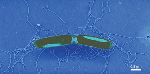
Metal shadowed bacteria, Proteus mirabilis, rotary shadowed with platinum–palladium at 30°. The image was recorded at 20 KX
-
5.
With two pairs of forceps, cleave the mica squares into two sheets.
-
6.
With its freshly cleaved side up, place the mica below the spray apparatus. During spraying, the mica sheet should either be fixed with a piece of double-sided adhesive tape or held in position with a pair of forceps.
-
7.
Briefly (i.e., for about 1 s) press the button of the air can (see Fig. 5) to spray the sample suspension onto the freshly cleaved mica.
Fig. 5 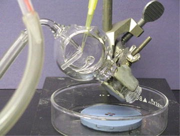
Loading spraying apparatus
-
8.
Immediately mount the sprayed mica sheet with double-sided adhesive tape onto the rotary table of the vacuum evaporator. Close the Jar on the vacuum apparatus and proceed to Subheading 3.2.


3.1.2 Spraying on Freshly Prepared Carbon Stabilized Formvar Support Grids
-
1.
Dilute the sample with 100 mM Ammonium Acetate (0.1–1.0 mg/ml for most proteins) and pipette 25 μl into an Eppendorf tube (see Note 8).
-
2.
Add 100 % glycerol to the sample (i.e., to a final glycerol concentration of 30–50 %) using a transfer pipette. Mix thoroughly with the pipette and vortex.
-
3.
Draw 25 μl of the glycerol-containing solution into a micropipette and load it into the spray apparatus (see Fig. 5).
-
4.
With a pairs of forceps place four to five freshly prepared or purchased support grids (see Note 4) below the spray apparatus. Using a silicon rubber pad for this eliminates the need to use adhesive tape to secure a piece of Parafilm in place and makes the transfer into the Vacuum Evaporator much easier (see Note 3).
-
5.
Briefly (i.e., for about 1 s) press the button of the air can (see Fig. 6) to spray the sample suspension onto the prepared grids.
Fig. 6 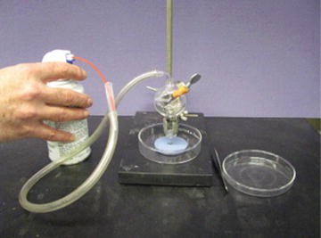
Spraying samples onto prepared grids
-
6.
Immediately mount the sprayed grids on the silicon rubber sheet onto the rotary table of the vacuum evaporator—no adhesive tape is needed. Close the jar on the vacuum apparatus and go to methods Subheading 3.2.

3.1.3 Spontaneous Adsorption Method for Nucleic Acids
-
1.
Prepare a solution at pH 6 containing 0.1–0.2 pg/ml DNA, 1.3 pg/ml cytochrome C, 0.07 M formaldehyde, and 0.15 M ammonium acetate at room temperature and immediately poured this solution into a clean Teflon-coated dish until the liquid meniscus is about 2 mm above the hydrophobic rim.
-
2.
If necessary, the surface may be cleaned by sweeping with a Teflon-coated Pasteur Pipette.
-
3.
A freshly prepared or purchased support grid is floated face down to the surface of the solution for 10 min (see Note 4).
-
4.
Transfer the grid to the surface of a droplet of 95 % ethanol for 10 s.
-
5.
Then placed the grid face down on a number 50 (hard) filter paper.
-
6.
Immediately mount the grids (face up) onto the silicon rubber sheet and transfer this to the rotary table of the vacuum evaporator—no adhesive tape is needed. Close the jar on the vacuum apparatus and go to Subheading 3.2.
3.1.4 Droplet Method for Nucleic Acids
-
1.
Prepare a solution at pH 6 containing 0.1–0.2 pg/ml DNA, 1 % formaldehyde, and 0.15 M ammonium acetate is prepared at room temperature.
-
2.
A single droplet of this solution is placed onto a piece of Parafilm.
-
3.
Float a freshly prepared or purchased carbon-coated Formvar support face down to the surface of the solution for 20 min (see Note 4).
-
4.
Transfer the grid, face down to a droplet of 95 % ethanol for 10 s.
-
5.
Then placed the grid face down on a number 50 (hard) filter paper (see Notes 5 and 6).
-
6.
Immediately mount the grids (face up) onto the silicon rubber sheet and transfer this to the rotary table of the vacuum evaporator—no adhesive tape is needed. Close the Jar on the vacuum apparatus and go to Subheading 3.2(Fig. 7).
Fig. 7 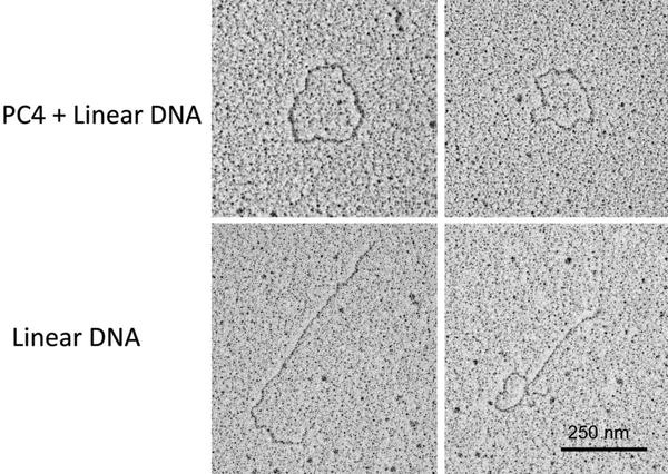
Single strand DNA with PC4 protein prepared as described above in the Droplet method with 1 % formaldehyde, rotary shadowed at 6° with Platinum–Palladium 80:20. When the single strand DNA is spread in the presence of the protein PC4, the strands form loops, without the protein all you see are linear strands. Images courtesy of Dr. Lijain Yu at the University of Massachusetts Medical School

3.1.5 Mica Sandwich Technique for Rotary Shadowing (See Note 7)
-
1.
Hold a piece of mica with a pair of straight forceps and cut it into square pieces (5–7 cm) with a pair of scissors. Cleave the mica sheets and set aside.
-
2.
Dilute the sample with 100 mM Ammonium Acetate (pH 7.2) to a concentration of 15–30 mg/ml for most proteins and pipette 25 μl into an Eppendorf tube (see Note 8).
-
3.
Add 100 % glycerol to the sample (to a final glycerol concentration of 40–70 %) using a transfer pipette. Mix thoroughly with the pipette and vortex.
-
4.
Draw several drops of the glycerol-containing solution into a micropipette and load it onto the freshly cleaved side of a piece of the mica and then place the other side of the mica on top to make the sandwich.
-
5.
Allow the macromolecules to adhere to the mica surface for 5 min.
-
6.
Separate the mica sheets and immediately place them onto a piece of double-sided adhesive tape to secure them to the rotary stage of the vacuum apparatus.
-
7.
Close the Jar on the vacuum apparatus and go to Subheading 3.2.
3.1.6 Spreading of Viruses and Bacteria for Metal Shadowing
-
1.
Hold a grid with a freshly prepared carbon stabilized Formvar support film (see Note 4) with a pair of straight forceps and place one 3–5 μl drop of prepared specimen (e.g., viral prep or bacterial prep) onto the carbon surface.
-
2.
Wait 30 s to allow the specimen to adhere to the carbon surface and wick away the excess with a piece of filter paper, leaving just a thin film of liquid on the carbon surface.
-
3.
Holding the grid with the forceps at approximately 30° from upright, run six to eight drops of 1 % uranyl acetate over the prepared surface (see Note 9).
-
4.
Wick the uranyl acetate away with a piece of filter paper and place the prepared grids into your vacuum evaporator.
-
5.
Close the Jar on the vacuum apparatus and go to Subheading 3.2.
Note: the single exception to the standard metal evaporation technique is that your filament angle has to be set to at least 30° or higher for these types of specimens to avoid the kind of artifacts that were discussed earlier (Fig. 8).

Adeno-Associated Virus (AAV), first negative stained with 1 % uranyl acetate to stabilize the virions and then rotary shadowed with platinum–palladium (80:20) at 30°. The image was recorded at 46 KX, the stage tilted to 45°. Courtesy of Dr. Guangping Gao, University of Massachusetts Medical School
3.2 Standard Metal Evaporation Techniques
(Turn on and the power to your vacuum evaporator and start up the vacuum system prior to preparing your samples for shadowing. Be sure to follow your instrument manufacturer’s operating instructions when initializing the vacuum system. Make sure that you have adequate water flow to your system if you have a water cooled high vacuum system.) (Fig. 9).

Denton 502B Vacuum Evaporator
3.2.1 Unidirectional Shadowing
-
1.
Switch on the thin film quartz monitor.
-
2.
Prepare the evaporator for metal evaporation on one set of electrodes and carbon evaporation on the second set of electrodes according to the instruction manual of the instrument manufacturer.
-
3.
The recommended working distance between the metal filament tip and the middle of the table is 10–12 cm and the tilt angle of the table relative to the evaporation axis should be around 6° for low-angle shadowing. The recommended working distance for the carbon electrodes is the same, but the tilt angle should be 80–90° to the table (Fig. 10).
Fig. 10 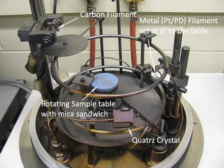
The inside view and setup of the vacuum evaporator for metal shadowing
-
4.
Mount the samples onto the table. Close the chamber and start the vacuum sequence.
-
5.
Pour liquid nitrogen into the Meissner trap.
-
6.
When the vacuum meter reads better than 2 × 10⁻⁶ mbar you may begin the evaporation sequence.
-
7.
Degas and preheat metal filament according to the instruction manual of the instrument supplier. The Denton 502 B Evaporator has a manual shutter that can be employed to prevent metal deposition while you are melting your metal wire on the Tungsten filament. Older instruments were not equipped with shutters and the initial filament conditioning had to be done prior to loading the specimen.
-
8.
Set the thin film quartz monitor to zero.
-
9.
Open the manual shutter. Start evaporating the chosen metal (from Table 1) according to the instrument’s instruction manual.
-
10.
Read the thickness on the thin film quartz monitor. After the deposition of about 0.5–1.0 nm on the thickness indicator, close the manual shutter and stop evaporation.
If you are shadowing on support grids release the vacuum in the chamber and remove the prepared samples from the vacuum chamber. They are now ready for viewing in your TEM. These types of specimens are very stable and may be stored indefinitely in clean grid boxes.
For shadowing on mica proceed to step 11.
-
11.
Evaporate carbon according to the instrument’s instruction manual. After the deposition of about 0.1–0.3 nm on the thickness indicator, close the manual shutter and stop evaporation and open the vacuum chamber.
-
12.
Carefully float the metal rendering of the specimen off of the mica onto the surface of the water (see Fig. 11), allowing the replica to relax on the water surface for a few minutes. Next pick up the film with copper grids as one would pick up sections from the boat of a knife in ultramicrotomy (see Fig. 12). Your specimens are ready to be observed in your TEM. Carbon stabilized, metal shadowed specimens are very stable and may be stored indefinitely in clean grid boxes.
Fig. 11 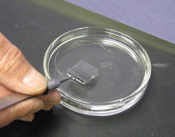
Floating carbon–metal film off of the sheet of mica. In this case there are two sheets of mica (opposing sides of the mica sandwich). Both sides will be metal shadowed and carbon coated to produce the metal rendering of the molecular sample
Fig. 12 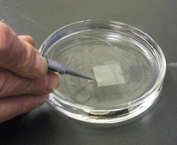
Picking up the metal renderings on bare copper grids. Simply pick up pieces of the film as it floats on the water surface. Many grids are collected from each side of the mica sandwich


3.2.2 Rotary Shadowing
Proceed as described above Subheading 3.2.1 to step 7.
-
8.
Start the motor of the rotating base (set to about 120 rpm).
-
9.
Set the thin film quartz monitor to zero.
-
10.
Open the manual shutter. Start evaporating the chosen metal (from Table 1) according to the instrument’s instruction manual.
-
11.
Read the thickness on the thin film quartz monitor. After the deposition of about 0.5–1.0 nm on the thickness indicator, close the manual shutter and stop evaporation.
-
12.
Evaporate carbon according to the instruction manual of the instrument supplier. After the deposition of about 0.1–0.2 nm on the thickness indicator, close the manual shutter and stop evaporation.
-
13.
Turn the rotating table off, break the vacuum, and remove the prepared samples from the vacuum chamber.
If you are shadowing on support grids you are finished and your specimens are ready to be observed in your TEM.
For shadowing on mica proceed to step 14.
-
14.
Carefully float the metal rendering of the specimen off of the mica onto the surface of the water (see Fig. 11), allowing the replica to relax on the water surface for a few minutes. Next pick up the film with copper grids as one would pick up sections from the boat of a knife in ultramicrotomy (see Fig. 12). Your specimens are ready to be observed in your TEM. These are very stable sample and may be stored indefinitely in clean grid boxes.
4 Notes
-
1.
While it is useful to know how much metal is needed to produce the desired metal shadow, it is often more empirical than calculated. There is however a fairly simple calculation based on the shadow angle and the density of the metal that you are using, that can be helpful in setting up the vacuum apparatus and producing your first metal shadowed specimens [8].
$$ M=\frac{4\pi {r}^2 t\rho}{ sin\alpha} $$M = the weight of the metal in grams
r = the distance from the source to the specimen
t = the thickness of the deposit in Å
ρ = the density of the metal you are using in g/cm3
α = the shadowing angle
For further information on the refractory properties of these metals the reader is referred to the Handbook of Chemistry and Physics.
-
2.
While chromium provides very thin continuous films down to 0.03–0.05 nm that adhere tightly to the specimen, if not imaged and recorded immediately they will appear very granular due to the almost immediate oxidation to chromium oxide, rendering the specimens unusable for further observation and analysis.
-
3.
A new silicon rubber embedding mold can be used (inverted) as a grid pad if you do not have silicon rubber pad on hand. Grids will stick to this surface without slipping and the pad will stick to the table of the vacuum evaporator without the use of double sided adhesive tape.
-
4.
To ensure a smooth, even spread of sample and stain, the support film must be hydrophilic. A freshly carbon-coated grid will provide good spreading, but older grids may not. Methods for returning hydrophobic grids to a state where they will provide an acceptable, even spreading of your sample have been described [4]. The best way is to glow discharge them if a vacuum evaporator or a glow discharge device if one is available. If you do not have access to a glow discharge devise, an easy and surprisingly effective method is to treat the grids on a drop of 1 % aqueous Alcian blue for 5 min and then wash them on three to five drops of water until the rinse droplets are clear. These procedures should be done just prior to adsorbing the sample suspension. There is some question about how long the grids remain fresh; some publications suggest 30 min others insist that the carbonized films must be “aged” in a refrigerator for at least a week prior to use. I have always found that freshly prepared carbonized Formvar support films work best if made fresh the day you need them. However, if they are stored in a petri dish sealed with Parafilm, they can remain hydrophilic for several days.
-
5.
The Cytochrome C method has been proven enormously useful and popular for observation of nucleic acids, but it cannot be satisfactorily used for association of nucleic acids with protein molecules, such as enzymes because of the obscuring effect of the bound Cytochrome C on the protein [23].
-
6.
Banerjee and Iyer reported that when the droplet method is used to visualize the linearized plasmid DNA (pCU 918), a significant fraction of molecules (30–40 %) are circular [24]. They suspected that because of the small surface area of the droplets, spreading of the protein becomes exceedingly difficult to control and it may serve to promote such artificial circularization of the plasmids. Therefore, they recommended that when the droplet method is used, formaldehyde is essential to prevent this artifact.
-
7.
Freeze-drying has also been used with the sandwich procedure and may provide certain advantages over glycerol drying. However, the overall distribution of macromolecules is not so uniform, and when specimen preparations are viewed at low magnification they exhibit a “patchy” appearance. This patchiness is probably due to material being torn from the surface as the thin layer of ice is cleaved. Nevertheless, large areas of intact material with evenly distributed filaments can usually be found [25].
-
8.
It should be noted that the presence of nonvolatile salts, up to physiological concentrations, can be used with this technique as the retreating edge of the evaporating layer of glycerol–buffer appears to sweep along unabsorbed molecules and salt ions still in solution, leaving the molecules of interest adsorbed unto the mica [12]. When freeze-drying, instead of glycerol drying, was used they also found that the sandwich technique was insensitive to concentrations of nonvolatile salts up to physiological concentrations. However, when higher concentrations of salts were used (e.g., NaCl up to 400 mM, Tris up to 100 mM, or phosphate up to 76 mM), washing the mica sheets with the absorbed macromolecules with ammonium acetate was necessary prior to vacuum drying to achieve consistently good results.
-
9.
The uranyl acetate fixes and stabilizes the viruses and bacteria as well as protecting them from the forces of air drying [26]. Washing the prep with a few drops of 30 % glycerol in ammonium acetate buffer works as well as negative staining with uranyl acetate and has been reported to preserve the integrity of the particles as well as critical point drying [27, 28].
References
Marton L (1934) La microscopie electronique des onjectes biologiques. Bull Acad Belg Cl Sci 20:439–466
Schaefer FJ, Harker DJ (1942) Surface replicas for use in the electron microscope. J Appl Phys 13:427–433
Sharp DG, Lanni F, Beard JW (1950) The egg white inhibitor of influenza virus hemagglutination. J Biol Chem 185:681–688
Heinmets F (1949) Modification of silica replica technique for study of biological membranes and application of rotary condensation in electron microscopy. J Appl Physiol 20:384–388
Neugebauer D-C, Zingsheim HP (1979) Apparent holes in rotary shadowed proteins: dependence on angle of shadowing and replica thickness. J Microsc 117:313–315
Hirokawa N, Heuser J (1982) The inside and outside of gap-junction membranes visualized by deep etching. Cell 30:395–406
Chandler DE (1986) Rotary shadowing with platinum-carbon in biological electron microscopy: a review of methods and applications. J Electron Microsc Tech 3:305–335
Wischnitzer S (1970) Introduction to electron microscopy, 2nd edn. Pergamon Press, New York
Bradley DE (1959) High-resolution shadow-casting technique for the electron microscope using the simultaneous evaporation of platinum and carbon. Br J Appl Physiol 10:198–203
Bachmann L, Hayek K (1962) Beschattung elektronenmikroscopischer praparate mit hochstschmelzenden metallen. Naturwissenschaften 49:153
Hall CE (1956) Visualization of individual macromolecules with the electron microscope. Proc Natl Acad Sci USA 42:801–806
Tyler JM, Branton D (1980) Rotary shadowing of extended molecules dried from glycerol. J Ultrastruct Res 71:95–102
Nermut MV, Eason P (1989) Cryotechniques in macromolecular research. Scanning Microsc Suppl 3:213–224, discussion 224–225
Fowler WE, Aebi U (1983) Preparation of single molecules and supramolecular complexes for high-resolution metal shadowing. J Ultrastruct Res 83:319–334
Krementsoy DN, Krementsova EB, Trybus KM (2004) Myosin V regulation by calcium, calmodulin, and the tail domain. J Cell Biol 164:877–886
Kleinschmidt A, Zahn RK (1959) Über Desoxyribonuleinsäure Molekülen in Protein Mischfilmen. Z Naturforsch 14b:770–779
Mould PA, Holmes DF, Kadler KE et al (1985) Mica sandwich technique for preparing macromolecules for rotary shadowing. J Ultrastruct Res 91:66–76
Goldsmith CS, Miller SE (2009) Modern uses of electron microscopy for detection of viruses. Clin Microbiol Rev 22:552–563
Kapikian AZ, Wyatt RG, Dolin R et al (1972) Visualization by immune electron microscopy of a 27-nm particle associated with acute infectious nonbacterial gastroenteritis. J Virol 10:1075–1081
Rodgers FG, Davey MR (1982) Ultrastructure of the cell envelope layers and surface details of Legionella pneumophila. J Gen Microbiol 182:1547–1557
Lin Y, Yan X, Cao W et al (2004) Probing the structure of the SARS coronavirus using scanning electron microscopy. Antivir Ther 9:287–289
Geisbert TW, Jahrling PB, Hanes MA et al (1992) Association of Ebola-related Reston virus particles and antigen with tissue lesions of monkeys imported to the United States. J Comp Pathol 106:137–152
Lang D, Mitani M (1970) Simplified quantitative electron microscopy of biopolymers. Biopolymers 9:373–379
Banerjee SK, Iyer NV (1995) Quick and easy spreading techniques for electron microscopy of DNA. Biotechniques 18:946–947
Haqshenas G, Shivaprasad HL, Woolcock PR et al (2001) Genetic identification and characterization of a novel virus related to human hepatitis E virus from chickens with hepatitis-splenomegaly syndrome in the United States. J Gen Virol 82:2449–2462
Hayat MA, Miller SE (1990) Negative staining: applications and methods. McGraw-Hill, New York
Brown DT, Brown NC, Burlingham BT (1972) Morphology and physical properties of Staphylococcus bacteriophage p 11–M15. J Virol 9:664–671
Sarkar NH, Manthey WJ, Sheffield JB (1975) The morphology of murine oncornaviruses following different methods of preparation for electron microscopy. Cancer Res 35:740–749
Author information
Authors and Affiliations
Editor information
Editors and Affiliations
Rights and permissions
Copyright information
© 2014 Springer Science+Business Media, New York
About this protocol
Cite this protocol
Hendricks, G.M. (2014). Metal Shadowing for Electron Microscopy. In: Kuo, J. (eds) Electron Microscopy. Methods in Molecular Biology, vol 1117. Humana Press, Totowa, NJ. https://doi.org/10.1007/978-1-62703-776-1_5
Download citation
DOI: https://doi.org/10.1007/978-1-62703-776-1_5
Published:
Publisher Name: Humana Press, Totowa, NJ
Print ISBN: 978-1-62703-775-4
Online ISBN: 978-1-62703-776-1
eBook Packages: Springer Protocols