
Abstract
A large-size direct shear test was conducted to test the interface of dredger fill and concrete. The effect that concrete strength and the density of dredger fill have on the properties of interface is then analyzed. Digital photography was used to record soil particles of dredger fill moving near the interface, and the particle images were analyzed by particle image velocimetry technique. The results of the tests show that the shear strength of interface fit the model laid out in the Mohr–Coulomb theory. The relationship between shear displacement and shear stress fit the hyperbola model. Soil particles of dredger fill near the interface have large horizontal displacement and obvious vertical displacement of the particles. Under high normal stress, concrete strength has significant influences on the shear strength of interface. Density of dredger fill has great effects on the shear strength of interface.
Introduction
Problems with the interaction between soil and structure interface are common in actual projects (such as pile-foundation systems, retaining wall systems, slope protection structure systems) which involve the mechanical characteristics of nonlinearity, large deformation, partial discontinuity, and other mechanical characteristics. When soil and concrete structure interact with each other, the concrete structure is bounded elastic material, and the soil is semi unbounded elastic–plastic material. Due to difference in material mechanics between two sides of the contact surface, the contact surface will be deformed and result in a larger shear stress [1]. Therefore, it is important for interface behavior between soil and concrete to analyze the stress and deformation of structural contact surface, the development of shear failure, and the load transfer process. Mechanical characteristics between soil and structure interface directly affects the quality of the project. Thus, studies about soil and structure interface have always been a key subject of geotechnical engineering. According to the research up to now, some of them are about the analysis of the effects of joint roughness coefficiency, structural planes category, and the type of soil and other factors on mechanical characteristics of contact surface. Desai et al. [2] studied static and dynamic characteristics of contact surface between soils and structure material. Based on the results of the direct shear test, a damage mechanics constitutive model for rough contact surfaces is established by Hu and Pu [3, 4], which can reflect strain softening and dilatancy phenomena in the shear deformation of contact surfaces. Miller et al. [5] modified a commercially-available direct shear apparatus for testing unsaturated soil and interfaces between unsaturated soil and stainless steel. Through a series of monotonic direct interface shear tests, DeJong et al. [6] examined localized soil-structure interaction through a series of monotonic direct-interface shear tests. Relative density, particle angularity, particle hardness, surface roughness, normal stress, and normal stiffness were among the parameters investigated. Hossain et al. [7] studied the interface shear strength increases with grouting pressure at saturated conditions. The rate of increase of shear strength with matric suction is greater for completely decomposed granite soil compared to soil–cement interface. Taha and Fall [8] studied the interface shear behavior of Leda clay-concrete: Leda clay specimens with various dry densities and salt contents were used to study the influence of these parameters on the interface shear behavior. Alejandro and David [9] conducted interface shear tests between cone penetration test friction sleeves of differing roughness and sands. Borana et al. [10] modified the fabrication of the shear box base/test cell for interface testing. Others studies analyzed the relationship between the shear stress and shear displacement of contact surface. Studies concerning the mechanical characteristics of contact surface often used plastic, elastoplastic, and Clough–Duncan nonlinear elastic models to describe shear stress-shear deformation curves. Clough and Duncan [11] studied the mechanical characteristics of contact surface between soil and concrete by direct shear tests, pointing out the hyperbolic curve of the interface shear stress and relative shear displacement. Evgin and Fakharian [12, 13] conducted two-dimensional and three-dimensional tests of the interface between soil and steel to study the effect of the stress-displacement under different stress paths. Shahrour and Rezaie [14] created a constitutive model of contact surfaces of silica sand by cyclic loading tests of the contact surface of silica and sand. Mortara et al. [15] obtained the formulation of a simple elastoplastic model for the behavior of smooth sand–steel interfaces; the model is derived from a series of constant, normal-stiffness direct shear tests between siliceous sand and smooth steel plate. Some scholars study the mechanical characteristics of contact surface soil and structure by numerical analysis [16,17,18,19,20] and explore the interface shear strength theory and test method based on the micro-structure between particles [19, 21,22,23,24]. Available documents indicate that there are no studies concerning the influence of the strength of concrete interface and soil conditions themselves on the interface shear strength, and that there is no correlation model about the mechanical characteristics of contact surface between dredger fill and structure. Meanwhile, research based on the micro-structure between particles is still in the exploratory stage. Further study of how soil particles near the contact surface transfer shear force is necessary.
Therefore, in this paper, direct shear tests of dredger fill in different conditions and concrete under different strengths were conducted with large direct shear apparatus in Tongji University. The displacement of dredger fill particles near the interface during shear process is observed by particle image velocimetry (PIV). Interface shear characteristics of dredger fill-concrete are also analyzed.
Method and material
Test apparatus
The direct shear test is a large structure-plane shearing apparatus (SJW-200) developed by Tongji University. Its main technical parameters are shown in Table 1, and the shear apparatus is shown in Figs. 1 and 2. SJW-200 can provide an interface with size 600 mm × 400 mm. The apparatus can provide differing frequencies of cyclic loading and static loading in the vertical direction. Cyclic shear tests can also be conducted in the horizontal direction. Test data, including shearing stress, shearing displacement, normal stress, normal displacement and time are collected automatically by the equipment. The test data collection interval is 2 s in the tests.

Shear device (SJW-200)

Diagram of direct shear apparatus (mm)
Displacement of dredger fill particles near the interface is captured with the camera through plexiglass windows. Camera takes a photo every 5 s automatically.
Material of test
The interface in tests is concrete slab. According to the shear formula G = 2E/(1 − υ), the shear stress of interface depends on the properties of the structural material and the surrounding soil. For prefabricated pipe pile, surface roughness of concrete is similar, but the concrete strength is difference. So, in this paper, effect of surface roughness of concrete on interface behavior is not considered. In order to eliminate surface roughness difference of concrete slab, the concrete slab is polished by same sanding. In order to analyze the effect of concrete strength on interface behavior between soil and concrete, three concrete slabs with compressive strength of C30, C40, and C50 are made separately. The compounding ratio of concrete slab meets specification for mix proportion design of ordinary concrete (JGJ55-2011). The size of concrete slab is 600 mm × 400 mm × 100 mm. The elastic modulus of the concrete slab is shown in Table 2.
Dredger fill are taken from Dishui Lake area in Shanghai Lingang New District. Preparation of specimen and the saturation process are conducted strictly according to standard for soil test method (GB50123-1999). Saturation degree (Sr) of the specimen is 0.95. Model size of dredger fill is 600 mm × 400 mm × 100 mm. Before each Shear Test start, soil samples were consolidated for 24 h under 20 kPa of normal stress. Basic physical properties of remolded dredger fill are shown in Table 3.
Test procedures
The procedure of the direct shear tests on the interface between dredger fill and concrete is as follows:
-
1.
In order to reduce friction in the system, Vaseline is smeared on the steel plate of an upside shear box and down-side shear box, inside the walls of steel plates of upside shear box, and the trolley wheels.
-
2.
Place the concrete slabs in downside shear box, and place the dredger fill soil sample in the upside shear box. According to the different mass ratio, the test soil is prepared by mixing the soil and dyed sand.
-
3.
The control points are marked in the shear box glass. Fourteen vertical observation belts and seven horizontal observation belts are arranged vertically and horizontally. It is shown in Fig. 3. Through observing the horizontal displacement and vertical displacement of dyeing sand in horizontal and vertical observation zones, the particle deformation of the distance shear interface is obtained.
Fig. 3 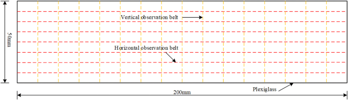
Horizontal and vertical observation belt
-
4.
Fix the camera and adjust it to make sure that camera can take clear photos of dredger fill particles near the interface through the plexiglass window.
-
5.
Turn on the apparatus, then move the shear boxes to the shear position.
-
6.
Open the strain-control mode, set the rate of shearing of 2 mm/min, start shearing and taking photos.

Analysis of test result
Relationship between stress and displacement of interface
Shear stress and shear displacement curves of interface under different normal stress with different soil sample are shown in Figs. 4, 5 and 6.

Curve of shear stress and shear displacement of soil sample 1

Curve of shear stress and shear displacement of soil sample 2

Curve of shear stress and shear displacement of soil sample 3
Shear stress and shear displacement curve of interface between dredger fill and concrete shows that the strength of interface increases with the increase of normal stress. No obvious peak value of shear stress appears when shear failure occurs on the interface. No softening behavior of shear stress appears with the increase of shear displacement. Figures 4, 5 and 6 shows that relationship between shear stress and shear displacement curves fits the hyperbola model.
Shear strength of interface
Ultimate shear strength of each interface under different normal stress was shown in Table 4. Interface strength curve due to different soil samples is shown in Fig. 7.

Curve of shear stress and normal stress of interface strength
Figure 7 shows that within the range of normal stress in the test, the relationship between shear strength and normal stress of interface fit the Mohr–Coulomb strength theory model:
where: τm—ultimate shear stress of interface, kPa; σ—normal stress, kPa; c—cohesion of interface, kPa; \(\varphi\)—friction angle of interface.
The fitting result, cohesion, and the friction angle of the interface under differing densities of dredger fill and normal stress are shown in Table 5.
Shear stress and shear displacement hyperbola model of interface
Mechanical characteristics of interface are mostly described with the rigid plastic model, the ideal elastoplastic model, and the Clough–Duncan nonlinear elastic model [24, 25]. Figures 4, 5 and 6 shows that the mechanical transfer equation of interface between dredger fill and concrete fits the hyperbola model (shown in Fig. 8). Shear stress approaches ultimate shear stress with the increase of shear displacement, and there is no peak value.

Curve of hyperbola model of shear stress and shear displacement
Transfer equation expression is as follow:
where: τ—shear stress of interface, kPa; u—shear displacement of interface, mm; a, b—constants to be determined.
When the shear displacement (u) of interface approaches infinite, the shear stress of interface approaches a constant.
Therefore, the physical meaning of b is a constant described ultimate shear stress of interface.
When the shear displacement approaches zero,
The physical meaning of \(\bar{K}\) is the gradient τ ~ u curve approaches origin.
Equation (2) can be rewritten as:
where: \(\bar{K}\)—gradient when u → 0; \(\tau_{m}\)—ultimate shear stress of interface.
For this test, fitting curves were shown in solid line in Figs. 4, 5 and 6. The parameters of interface shear stress and shear displacement fitting curve of soil sample are shown in Table 6.
If one compares the fitting curve shown in Figs. 4, 5 and 6 and the correlation coefficients in Table 6, it can be seen that the fitting values are in good agreement with test data. Thus, the relationship between shear stress and the displacement of dredger fill and concrete interface can be described by Eq. (5). The shear stress-displacement curve of dredger fill and concrete interface can also be predicted by Eq. (5).
Particle displacements of dredger fill
Displacement information of trace points in dredger fill can be recorded by particle image velocimetry technology (PIV) [26, 27]. After direct shear tests of the interface of dredger fill and concrete, the image sequence recorded of dredger fill particles will be treated by the particle image velocimetry analysis software Micro Vec V2.0. The result of soil sample 2 with concrete slab strength of C40 and normal stress of 200 kPa is given in this paper. The control points are marked in the shear box glass. Fourteen observation belts in vertical deformation and seven observation belts in horizontal deformation are arranged (Fig. 3). Through observing the horizontal displacement and vertical displacement of dyeing sand in horizontal and vertical observation zones, the particle deformation of the distance shear interface was obtained. Further, the result is shown in Figs. 9 and 10.

Curve of horizontal displacement of soil sample 2 with concrete slab strength of C40 and normal stress of 200 kPa

Curve of vertical displacement of soil sample 2 with concrete slab strength of C40 and normal stress of 200 kPa
Figures 9 and 10 show that when the dredger fill particles’ distance from interface is greater than 10 mm, horizontal displacement and vertical displacement of dredger fill particles both increase in correlation with shear displacement. When the dredger fill particles’ distance from the interface is less than 10 mm, horizontal displacement increases, but vertical displacement decreases with the increase of shear displacement. The maximum horizontal displacement of dredger fill particles near the interface is 2.4 mm, and the maximum vertical displacement is 0.42 mm. There is obvious horizontal displacement and certain vertical displacement. When interface reaches maximum shear strength, changes of horizontal displacement and vertical displacement of dredger fill particles are very small with the increase of shear displacement. According to the analysis of the deformation between the contact surface of the concrete and soil with PIV technology, the formation of the shear zone in the shear process, the cause of the shear zone and the mechanism of the diffusion are obtained. The development of soil displacement near contact surface was analyzed.
Effect of concrete strength and density of dredger fill on interface
Effect of concrete strength on shear strength
The shear stress and displacement curve of dredger fill and concrete interface under differing concrete strengths are shown in Figs. 11, 12 and 13.

Curve of shear stress and shear displacement under normal stress 50 kPa

Curve of shear stress and shear displacement under normal stress 100 kPa

Curve of shear stress and shear displacement under normal stress 200 kPa
Figures 11, 12 and 13 show the effect of concrete strength on shear strength of interface increases with the increase of normal stress. When the normal stress is 50 kPa, 100 kPa and 200 kPa, the shear stress of concrete strength C50 interface respectively increases by 4%, 6.25% and 15.6% from that of concrete strength C30 interface. When the normal stress is less than 100 kPa, the effect of concrete strength on shear strength of interface is quite small. When the normal stress is greater than 200 kPa, the effect of concrete strength on shear strength of interface is significant. It means that when the embedded depth of the underground structure is more than 10 m and lateral stress intensity may be greater than 200 kPa, the effect of differing concrete strengths on the shear strength of interface under lateral stress should be taken into account.
The effect of the density of dredger fill on shear stress
Shear stress and displacement curve of dredger fill and concrete interface under different density are shown in Figs. 14, 15 and 16.
Figures 14, 15 and 16 show that the effects of density of dredge fill on shear strength of interface is great. In the same normal stress, ultimate shear stress of interface increases with the increase of density of dredger fill. Difference of ultimate shear stress of interface with different density of dredger fill increases with increase of normal stress. Strength of dredger fill was connected density of dredger fill. So, strength of dredger fill has influence on shear strength of interface.

Shear stress and shear displacement curve of different density under normal stress 100 kPa

Shear stress and shear displacement curve of different density under normal stress 200 kPa

Shear stress and shear displacement curve of different density under normal stress 400 kPa
Conclusions
-
1.
The shear strength of interface fit the Mohr–Coulomb strength theory model, while the relationship between shear displacement and shear stress of interface fit the hyperbola model.
-
2.
Large shear displacement and obvious normal displacement of dredger fill particles appear near the interface. The maximum horizontal displacement of dredger fill particles near the interface is 2.4 mm and the maximum vertical displacement is 0.42 mm.
-
3.
Effect of concrete strength on shear strength of interface increases with the increase of normal stress. When the normal stress is greater than 200 kPa, the effect of concrete strength on shear strength of interface is significant.
-
4.
The ultimate shear stress of interface increases with increase of density of dredger fill. The difference of ultimate shear stress of interface with different density of dredger fill increases with increase of normal stress.
References
Jianzhong Y, Min Y (2003) Test study on interface peculiarity of pile–soil interaction. Geol Prospect 39:276–279 (in Chinese)
Desai CS, Rigby DB (1997) Cyclic interface and joint shear device including pore pressure effects. J Geotech Geoenviron Eng ASCE 123(6):568–579
Li-ming HU, Jia-liu PU (2001) Experimental study on mechanical characteristics of soil–structure interface. Chin J Geotech Eng 23(4):431–435 (in Chinese)
Liming H, Jialiu P (2004) Testing and modeling of soil–structure interface. J Geotech Geoenviron Eng 130(8):851–860
Miller GA, Hamid TB (2007) Interface direct shear testing of unsaturated soil. Geotech Test J 30(3):182–191
DeJong JT, Westgate ZJ (2009) Role of initial state, material properties, and confinement condition on local and global soil-structure interface behavior. J Geotech Geoenviron Eng 135:1646–1660
Hossain MA, Jian-Hua Yin (2012) Influence of grouting pressure on the behavior of an unsaturated soil–cement interface. J Geotech Geoenviron Eng 138:193–202
Taha A, Fall M (2013) Shear behavior of sensitive marine clay–concrete interfaces. J Geotech Geoenviron Eng 139:644–650
Martinez A, Frost JD (2014) Axisymmetric shearing of sand–steel interfaces under axial and torsional loading. Geo-Congress 2014 Technical Papers vol. 234, pp 644–653
Borana L, Yin JH, Singh DN, Shukla SK (2015) A modified suction-controlled direct shear device for testing unsaturated soil and steel plate interface. Mar Georesour Geotechnol 33:289–298
Clough GW, Duncan JM (1971) Finite element analysis of retaining wall behavior. J Soil Mech Found Div ASCE 97(12):1657–1672
Evgin Erman, Fakharian Kazem (1996) Effect of stress paths on the behavior of sand steel interfaces. Can Geotech J 33(6):485–493
Fakharian Kazem, Evgin Erman (1997) Cyclic simple-shear behavior of sand–steel interfaces under constant normal stiffness condition. J Geotech Geoenviron Eng 123(12):1096–1105
Shahrour I, Rezaie F (1997) An elastoplastic constitutive relation for the soil–structure interface under cyclic loading. Comput Geotech 21(1):21–39
Mortara G, Ferrara D, Fotia G (2010) Simple model for the cyclic behavior of smooth sand–steel interfaces. J Geotech Geoenviron Eng 136:1004–1009
Frost JD, DeJong JT, Recalde M (2002) Shear failure behavior of granular–continuum interfaces. Eng Fract Mech 69:2029–2048
Sia AH, Dixon N (2007) Distribution and variability of interface shear strength and derived parameters. Geotext Geomembr. 25:139–154
Seo MW, Park JB, Park IJ (2007) Evaluation of interface shear strength between geosynthetics under wet condition. Soils Found 47(5):845–856
Kosoglu Laura, Filz George (2011) Modeling macro-scale clay secondary compression at micro-scale clay particle interfaces. Geo-Frontiers 2011:4273–4282
Kwak CW, Park IJ, Park JB (2014) Dynamic shear behavior of concrete–soil interface based on cyclic simple shear test. KSCE J Civil Eng 18(3):787–793
Hryciw RD, Irsyam M (1993) Behavior of sand particles around rigid inclusion during shear. Soils Found 33(3):1–13
Nakamura T, Mitachi T, Ikeura I (1999) Direct shear testing method as a means for estimating geogrid sand interface shear displacement behavior. Soils Found 39(4):1–8
Joseph E, Dove J, Bradley Jarrett (2002) Behavior of dilative sand interface in a geotribology framework. J Geotech Geoenviron Eng 128(1):25–37
Li-ming H, Jie MA, Bing-yin Z (2008) Simple shear test and numerical simulation of interfaces between granular materials. Rock Soil Mech 29(9):2319–2322 (in Chinese)
Dakuo Feng (2012) Three-dimensional constitutive laws, mechanism and model of gravel–structure interfaces. Department of Hydraulic Engineering, Tsinghua University, Bei Jing (in Chinese)
White DJ, Take WA, Bolton MD (2003) Soil deformation measurement using particle image velocimetry (PIV) and photogrammetry. Géotechnique 53(7):619–631
Chao Xu, Zhilong Shi (2011) Micro-measurement of soil particle movement in geogrid–soil interface direct shear test. J Tongji Univ 39(11):1605–1609 (in Chinese)
Acknowledgements
This investigation was supported by the Natural science foundation of Shanghai (Projects No. 14ZR1442800); the National Natural Science Foundation of China (Projects Nos. 41672274 and 41002093); Opening fund of State Key Laboratory of Geohazard Prevention and Geoenvironment Protection (Chengdu University of Technology) (Projects No. SKLGP 2014K013). The authors are extremely grateful for the financial support from these four organizations.
Authors’ contributions
PY designed the study and drafted the manuscript. SBX designed the large size direct shear test and analyzed interface shear characteristics of dredger fill and concrete. LS carried out the large size direct shear test. MD participated in the large size direct shear test. All authors read and approved the final manuscript.
Competing interests
The authors declare that they have no competing interests.
Publisher's Note
Springer Nature remains neutral with regard to jurisdictional claims in published maps and institutional affiliations.
Author information
Authors and Affiliations
Corresponding author
Rights and permissions
Open Access This article is distributed under the terms of the Creative Commons Attribution 4.0 International License (http://creativecommons.org/licenses/by/4.0/), which permits unrestricted use, distribution, and reproduction in any medium, provided you give appropriate credit to the original author(s) and the source, provide a link to the Creative Commons license, and indicate if changes were made.
About this article

Cite this article
Yang, P., Xue, SB., Song, L. et al. Interface shear characteristics of dredger fill and concrete using large size direct shear test. Geo-Engineering 9, 12 (2018). https://doi.org/10.1186/s40703-018-0081-3
Received:
Accepted:
Published:
DOI: https://doi.org/10.1186/s40703-018-0081-3