
Abstract
The pore air pressure of the soil layer has an obstructive effect on the infiltration of the rainfall-induced landslide. Therefore, the hydraulic hysteresis caused by air entrapment in the infiltration process of the slope also reduces the anti-sliding force of the slope. A method considered the air entrapment of the closed gas in soil particles’ pores is developed to study the time-delay effect and slope stability during rainfall. The Green–Ampt infiltration model is used to obtain the explicit analytical solution of the slope infiltration considering air entrapment. Moreover, the relationship between the safety factor, the rainfall duration, and the depth of the wetting front under the three rainfall conditions (qrain = 10, 26, 51 mm/h) is discussed. The results show that the air entrapment causes a significant time-delay effect of the landslide, and the hydraulic hysteresis is the strongest under the condition of heavy rainfall (qrain = 51 mm/h). The air-entrapment will have a supporting effect on the wetting front and reduce the slope normal stress. In infinite slope cases, the air entrapment under violent rainfall (qrain = 51 mm/h) will greatly reduce the slope safety factor.
Introduction
Rainfall-induced landslides are the most common type of landslide disaster (Higgitt et al. 2014; Li et al. 2020a, b), which caused devastating disasters to mountain residents, such as many economic losses and casualties (Saito et al. 2017; Fustos et al. 2020; Yang et al. 2020).
The Green–Ampt (GA) model is similar to Darcy’s law (Huo et al. 2020), so the model has a clear physical meaning and good scalability. Since GA model was proposed, it has been widely used in infiltration research. Many studies have made various amendments and supplements on the application conditions of the GA model, such as determining hydraulic parameters, the approximate solution of the theory, and the error analysis. A modified GA infiltration model was applied to the infiltration of stable rainfall conditions (Mein and Larson 1973), whereby, an improved GA model suitable for slope rainfall infiltration was proposed, and the sensitivity analysis of geometric parameters was performed (Chen and Young 2006); the optimal parameters of the GA model for the sand, sandy clay, and clay under the rainfall were obtained (Chen et al. 2015a, b). In general, the original GA model is used with the infinite slope model. The application range of these improved methods has been extended to landslides all over the world (e.g., Muntohar and Liao 2009, 2010; Zhang et al. 2017; Wu et al. 2018). In addition, the rainfall threshold is used as one of the indicators of rainfall-induced landslides (Cheng et al. 2020). Rainfall threshold is a common tool for analyzing the time-domain relationship of landslide disasters (Martinović et al. 2018). Therefore, the saturated hydraulic conductivity is usually used as the critical rainfall intensity threshold for the ponding water on the slope. In this paper, three rainfall intensity conditions are designed to investigate the impact of air entrapment on the stability of infinite slopes during rainfall.
The rainfall infiltration process and the slope failure are not entirely synchronized for the rainfall-induced landslide. Compared with rainfall, landslide hazards often have hysteresis and have a noticeable time-delay effect. The time-delay effect is mainly caused by the air entrapment during rainfall (Lu and Likos 2006; Lu et al. 2013; Chen et al. 2015a, b). The effect of air pressure in the soil during rainfall when the pores are closed was verified by Wang et al. (1997, 1998) through laboratory seepage tests. Test results pointed out that when the air overcomes the critical air pressure and breaks through the saturated soil layer and escapes the atmosphere, the pore air pressure of the unsaturated soil layer decreases. However, the air entrapment theory is mainly used in agricultural irrigation (Vereecken et al. 2019; Gonçalves et al. 2020). A laboratory test suitable for the Masa sandy loam soil from weathered granite rock and a TUAT light clay and soils from volcanic ash considering the effect of air entrapment on hydraulic conductivity was performed (Sakaguchi et al. 2005). Exhausted the air between pores in a vacuum environment, and then immerse in the water again to trap the air. The hydraulic conductivity measured by the falling head method decreases as the air content increases. An approach to combine the generalized stress framework with the suction stress retention and the suction stress characteristic curve was proposed (Lu and Godt 2008; Chen et al. 2017). The modified method indicated that it is necessary to consider the hydraulic hysteresis caused by air entrapment in rainfall-induced landslides. Otherwise, the failure possibility of the infinite slope will often be underestimated. The hydraulic hysteresis of the wetting front is verified by field and laboratory experiments, and the difference in soil between dry and wet conditions is critical for rainfall-induced landslides (Ebel et al. 2018). Whereas, the existed methods did not quantify the effect of air resistance and consider the process of increasing air entrapment in the strength failure criteria.
In summary, the objective of this paper is to develop a novel method based on air entrapment theory and the infinite slope model to simulate the infiltration in slopes and analyze the stability of rainfall-induced landslides.
Method
Assumptions
Rainfall-induced landslides have been an essential issue that geotechnical engineers have been paying attention to for a long time in geological disasters. However, the actual slope is often complicated. Therefore, to facilitate the solution, the infinite slope is usually used as the study object. The following assumptions need to be given before deriving the model:
-
1.
The rainfall is uniform, that is, the rainfall intensity is constant;
-
2.
When rainfall intensity is greater than the saturated permeability coefficient, the soil above the wetting front is saturated. Unsaturated soil with initial moisture content below the wetting front. In contrast, the soil is unsaturated.
-
3.
The bottom of the slope is regarded as impermeable bedrock, and the impact of groundwater on infiltration is not considered.
-
4.
The infinite slope in this paper is the clay slope.
Assumptions (1)–(3) are the assumptions of the Green–Ampt infiltration model in published literatures (Chen and Young 2006; Huang et al. 2008; Cevasco et al. 2014; Dolojan et al. 2021; Zhang et al. 2020). Assumption (4) is the applicable condition of the slope safety factor calculation method proposed in this paper.
Improved Green–Ampt infiltration model
-
a.
Traditional Green–Ampt infiltration model
The ground is considered horizontal in the traditional GA model (del Vigo et al. 2021), and its expression is
$$i(t) = K_{{\text{s}}} \frac{{z + \psi_{{\text{f}}} + h}}{z}$$(1)where i(t) is the infiltration rate at time t; z is the depth of the vertical wetting front; h is the depth of ponding water; ψf is the suction at the wetting front; Ks is the saturated permeability coefficient.
The application of GA model in slopes is different from that of horizontal ground, and the impact of slope angle on infiltration rate needs to be considered. The infiltration rate i1 determined by the rainfall intensity in the slope is
$$i_{1} = q_{{{\text{rain}}}} \cos \alpha$$(2)where qrain is the rainfall intensity; α is the slope angle.
During rainfall, the cumulative amount of infiltrated water (F) in the slope is obtained by the following equation:
$$F = z_{{\text{w}}} (\theta_{{\text{s}}} - \theta_{{\text{i}}} )$$(3)where zw is the depth of the wetting front on the vertical slope (as shown in Fig. 1); θs and θi represent the saturated moisture content and the initial moisture content, respectively.
Fig. 1 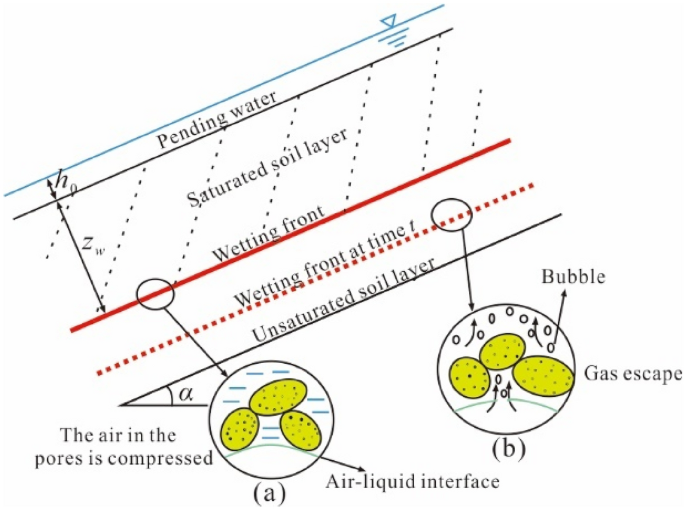
Porous air compressed-escaped process
After the GA model is extended to the slope, the Eq. (1) can be rewritten as
$$i(t) = \frac{{z_{{\text{w}}} \cos \alpha + \psi_{{\text{f}}} + h}}{{z_{{\text{w}}} \cos \alpha }}.$$(4)Substituting Eq. (3) into Eq. (4), the relation between F and i(t) can be obtained:
$$F = \frac{{\left( {\theta_{{\text{s}}} - \theta_{{\text{i}}} } \right)\left( {\psi_{{\text{f}}} + h} \right)}}{{i(t)/K_{{\text{s}}} - \cos \alpha }}$$(5) -
b.
Light rain-nonponding water model (qrain < Ks)
When the rainfall intensity qrain is less than the saturated permeability coefficient Ks, there will be no ponding water during the entire infiltration process. Therefore, it is necessary to solve the volumetric moisture content of the soil under the unsaturated state (Almedeij and Esen 2014). Van Genuchten (VG model) soil–water characteristic curve is usually used to describe the unsaturated hydraulic properties of soil (van Genuchten 1980). The expression of the VG model is
$$\theta \left( h \right) = \left\{ \begin{gathered} \theta_{{\text{r}}} + \frac{{\theta_{{\text{s}}} - \theta_{{\text{r}}} }}{{\left[ {1 + (\alpha \left| h \right|)^{n} } \right]^{m} }},h < 0 \hfill \\ \theta_{{\text{s}}} ,h > 0 \hfill \\ \end{gathered} \right.$$(6)where θ(h) is the volumetric moisture content function; θr is the residual moisture content; h is the pressure head; α and n are the recommended model parameters [in this paper, α = 3.5 m−1 and n = 1.5 (van Genuchten 1980)], and m = 1–1/n.
The relationship between rainfall intensity and pressure head is
$$q_{{{\text{rain}}}} = K_{{\text{s}}} \frac{{\left\{ {1 - (\alpha \left| {h_{{\text{w}}} } \right|)^{n - 1} \left[ {1 + (\alpha \left| {h_{{\text{w}}} } \right|)^{n} } \right]^{ - m} } \right\}^{2} }}{{\left[ {1 + (\alpha \left| {h_{{\text{w}}} } \right|)^{n} } \right]^{m/2} }}$$(7)where hw is the pressure head when the moisture content reaches θw.
By Eq. (7), the volumetric moisture content when the pressure head is hw can be obtained. Moreover, according to Eq. (3), the relationship between infiltration depth zw and time t is
$$z_{{\text{w}}} = \frac{{q_{{{\text{rain}}}} t}}{{(\theta_{{\text{w}}} - \theta_{{\text{i}}} )\cos \alpha }}.$$(8) -
c.
Heavy rain-ponding water model (qrain ≥ Ks)
When the rainfall intensity is greater than the saturated permeability coefficient, the soil above the wetting front is fully saturated at a specific infiltration time, and the air in the pores cannot be discharged. Therefore, when considering the pore gas pressure, the infiltration rate is mainly controlled by the permeability of the soil itself. Equation (3) can be written as
$$i(t) = K_{{\text{s}}} \frac{{\psi_{{\text{f}}} + z_{{\text{w}}} \cos \alpha + h_{0} - h_{{{\text{af}}}} }}{{z_{{\text{w}}} }}$$(9)where haf is the air pressure under the wetting front; h0 is the ponding water depth of the slope surface.
When ponding, infiltration rate i(t) is considered to be equal to rainfall intensity. Substituting Eqs. (3) and (9) into Eq. (5), then the accumulated infiltration volume Fp when water accumulates can be obtained:
$$F_{{\text{p}}} = \frac{{\left( {\theta_{{\text{s}}} - \theta_{{\text{i}}} } \right)\left( {\psi_{{\text{f}}} + h_{0} - h_{{{\text{af}}}} } \right)}}{{q_{{{\text{rain}}}} /K_{{\text{s}}} - \cos \alpha }}.$$(10)According to Eq. (10), the critical infiltration time tp can be obtained:
$$t_{{\text{p}}} = \frac{{F_{{\text{p}}} }}{{q_{{{\text{rain}}}} }} = \frac{{\Delta \theta (\psi_{{\text{f}}} + h_{0} - h_{{{\text{af}}}} )}}{{q_{{{\text{rain}}}} (q_{{{\text{rain}}}} /K_{{\text{s}}} - \cos \alpha )}}$$(11)where Δθ = θs − θi.
The critical wetting front depth zp can be expressed as
$$z_{{\text{p}}} = \frac{{\psi_{{\text{f}}} + h_{0} - h_{{{\text{af}}}} }}{{q_{{{\text{rain}}}} /K_{{\text{s}}} - \cos \alpha }}.$$(12)According to Darcy’s law, the analytical relationship between the depth and time of the wet front can be obtained as
$$t = \left\{ \begin{array}{*{20}{l}} \frac{{z_{{\text{w}}} \Delta \theta }}{{q_{{{\text{rain}}}} }},z_{{\text{w}}} \le z_{{\text{p}}} \\ t_{{\text{p}}} + A - B, z_{{\text{w}}} > z_{{\text{p}}} \\ \end{array} \right.$$(13)where A and B are, respectively:
$$\left\{ \begin{array}{*{20}{l}} A = \frac{{\Delta \theta \left( {z_{{\text{w}}} - z_{{\text{p}}} } \right)}}{{K_{{\text{s}}} \cos \alpha }} \hfill \\ B = \frac{{\Delta \theta \left( {\psi_{{\text{f}}} + h_{0} - h_{{{\text{af}}}} } \right)}}{{K_{{\text{s}}} \cos^{2} \alpha }}\ln \left( {\frac{{\psi_{{\text{f}}} + z_{{\text{w}}} \cos \alpha + h_{0} - h_{{{\text{af}}}} }}{{\psi_{{\text{f}}} + z_{{\text{p}}} \cos \alpha + h_{0} - h_{{{\text{af}}}} }}} \right) \hfill \\ \end{array} \right..$$(13a)Equation (13) is the GA model without considering the air entrapment. However, when ponding, the infiltration process is potentially affected by air compression ahead of the wetting front. As shown in Fig. 1a, the pore gas of the soil layer cannot escape from the slope in time during the downward movement of the wetting front. Therefore, the air under the wetting front is compressed, and the pore gas pressure gradually increases. When the pore pressure increases to a specific value (air-breaking value Hb), the air will break through the air–liquid interface to form bubbles and escape from the slope body (Fig. 1b).

Air entrapment theory
In summary, when considering the air entrapment effect, the pore gas pressure cannot be regarded as a constant. Theoretically, the pore gas pressure is related to the infiltration. In view of this, the reduction effect of pore gas has been verified through tests (Wang et al. 1997, 1998). Furthermore, analytical infiltration equations are also derived from the Green–Ampt model. It can be seen from the test results that the infiltration process is divided into two stages when ponding and air entrapment is considered (Fig. 1a, b). The air-breaking value Hb and the air-closing value Hc are used to describe the pressure head haf in the pore (Wang et al. 1997), and the Hb an Hc can be expressed as
where hab is the air-bubbling capillary pressure value; hwb is the water-bubbling value.
The pore gas pressure after considering air entrapment can be expressed as
Therefore, in the process of gas compression, when the pressure is maximum, an air-flow barrier will be formed, and the infiltration rate imin in this state is 0 m/h. According to Eq. (9), the infiltration depth z0 when the air pressure reaches the maximum value can be calculated:
where B is the depth of air-flow barrier below the soil surface, which is obtained by the test (Wang et al. 1997).
The infiltration time consumed when the infiltration rate is the smallest (the pore pressure is the largest) is
Calculation of infinite slope safety factor
For infinite slopes, the critical slip surface is often the wetting front. Therefore, the wetting front is regarded as the critical slip surface in this paper. The normal stress σn and sliding force τ at the bottom of the soil slice can be obtained:
When the wetting front moves downward, the pore gas in the unsaturated soil layer below the wetting front is compressed, forming an air–liquid interface at the wet front (Fig. 1). The compressed pore gas plays a supporting role on the upper saturated soil layer and slows down the tendency of rainwater infiltration. Therefore, the supporting force in the lower part of the wetting front can be written as
According to the Mohr–Coulomb criterion (Duncan et al. 2014; Renani and Martin 2020), the safety factor at the wetting front can be obtained as follows:
where cʹ is the effective cohesion; φʹ and φb are the effective internal friction angle and the internal friction angle related to suction, respectively.
Substituting Eqs. (19)–(21) into Eq. (22), the slope safety factor considering air entrapment can be obtained:
The pore gas pressure after considering the air entrapment can be obtained by Eq. (16). Equation (23) is the calculation method of slope safety factor considering air entrapment. The implementation steps of the method proposed in this paper are shown in Fig. 2.

Calculation flow chart
Validation
Many studies on the infiltration of layered soil have been carried out in recent years, and a method based on the same air entrapment theory (Wang et al. 1997, 1998) as in this paper has been proposed (Gan et al. 2019). In Gan’s method, one-dimensional infiltration-runoff experiments were used to measure the total infiltration considering air entrapment. Therefore, the total infiltration test results are used in this paper to verify the theoretical solution in this paper. Clay and sand were studied in one-dimensional infiltration-runoff experiments, but only the theoretical solution applicable to clay was verified in this paper. The hydraulic parameters of the soil used in the experiment are given in Table 1, and the other parameters are consistent with the clay in this paper.
In Fig. 3, the simulated data with traditional method is calculated by Eq. (10), the measured data is obtained through one-dimensional infiltration-runoff experiments, and the simulated data with air entrapment is obtained by the method proposed in this paper. It can be seen from Fig. 3 that the results of the traditional method and the test results have a large error, and the error becomes more and more significant with the progress of the infiltration process. The results of the proposed method are consistent with the trend of the test results, but the theoretical solution is smaller than test results on the whole. The air entrapment theory (Wang et al. 1997, 1998) believes that air is compressed during the infiltration process, and the pore gas pressure drops rapidly after exceeding the air-breaking value. Then this process is repeated again, but the difference is that each time this process is repeated, the pore gas pressure is lower than the previous pore gas pressure, so the pore gas pressure should be described by a non-linear reduction function. Unfortunately, it is difficult to test the porous air compressed-escaped process, so the linear relationship suggested by Wang (1997) is used to describe this paper. However, overall, the accuracy of the proposed method is much higher than that of the traditional method.

Relationship between the accumulated infiltration volume and rainfall duration
Application
A method to consider the impact of air entrapment on slope stability was also proposed by Chen et al. (2017), which is compared with the proposed method in the following. In this method, hydraulic hysteresis caused by air entrapment is described by suction stress characteristic curve (SSCC) and soil water retention curve (SWRC). The suction stress described by SSCC and SWRC can be obtained by Eq. (24). It can be seen from Eq. (24) that there are many physical parameters, and many tests are required to calibrate the parameters, which is more complicated for geotechnical engineers:
where αwa and nwa are empirical parameters; SMWA is the degree of saturation when a soil is wetting to zero suction state under the free wetting condition.
An actual landslide located in Alameda County, California (Fig. 4) was used in Chen’s method, so it was used to verify the proposed method in this paper. The detailed calculation parameters are given in Table 2. The Bay Area landslide is covered by the silt of approximately 1 m, derived from the weathering products of the underlying sandstone bedrock. Therefore, the Bay Area landslide satisfies the Assumption 4 in “Assumptions” section.

Schematic diagram of the field monitoring hillslope in Alameda County, California (Chen et al. 2017)
The relationship between slope safety factor and infiltration depth is shown in Fig. 5. It can be seen from Fig. 5 that the slope safety factors of the proposed method and Chen’s method both show a downward trend as the infiltration depth increases. In the early stage of infiltration, the difference in safety factor between Chen’s method and the proposed method is due to the fact that the suction given in this paper is a fixed value. Furthermore, as the wetting front depth increases, the safety factor obtained by the proposed method decreases faster. This is because air entrapment in Chen’s method is described by suction, which does not reflect the increasing characteristics of air entrapment. However, in the proposed method, the air will be compressed as infiltration processes, the pore gas pressure increases, and the normal stress decreases accordingly. In addition, the proposed method has the advantages of fewer parameters, convenient use, and easier estimation of the slope safety factor.

Relationship between safety factor and infiltration depth
Results and discussion
The shallow infinite slope (the schematic diagram is given in Fig. 6) is used as the case to investigate the impact of air entrapment. The detailed slope geometric parameters and mechanical parameters are shown in Table 3. The detailed hydrological parameters are shown in Table 4. Furthermore, critical values and rainfall intensity are of the five cases are listed in Table 5, and the other parameters are the same as those in Tables 3 and 4. It is worth noting that the selection criteria for the three rainfall conditions given in Table 5 are given in Table 6. Since the rainfall process during light rain is slow, the case of light rain will not be discussed.

Schematic diagram of the infinite slope
Hydraulic hysteresis caused by air entrapment
The relationship between the depth of the wetting front of the five cases and the rainfall duration is shown in Fig. 7. The soil physical parameters and hydraulic parameters are shown in Tables 3 and 4. In Fig. 7a, the results without the air entrapment are given by Eqs. (8) and (13). When considering the air entrapment, substituting Eq. (16) into Eqs. (8) and (13), the curve in Fig. 7b can be obtained.

Changes in the depth of the wetting front during rainfall
The qrain of Case 1 is less than Ks, so there is no air resistance in the infiltration process. It can be seen from Fig. 7a that the curves of Cases 2 and 3 are steeper than Case 1. This is because when qrain exceeds Ks of the soil, the infiltration is determined by the permeability of the soil. In Fig. 7b, when the rainfall duration exceeds the critical time tp, the air entrapment gradually takes effect. Cases 2 and 4 have obvious hydraulic hysteresis. Moreover, the air entrapment is the most significant in Case 4. The time for Cases 2 and 3 to reach a specific depth of infiltration is given in Table 7. It can be seen from Table 7 that air entrapment has a significant time-delay effect on the infiltration process. Whereas, as the depth of infiltration increases, the time difference between Cases 2 and 3 infiltration becomes larger and larger. Therefore, as the infiltration progresses, the time-delay effect becomes more obvious.
Infinite slope stability analysis
Here, the traditional shear strength theory method and the proposed method (Eq. 23) are used to calculate the safety factor. The relationship curve between safety factor and rainfall duration is shown in Fig. 8. It can be seen from Fig. 8a that the decrease rate of the slope safety factor of violent rain (Case 5) is greater than that of moderate and heavy rains (Case 1 and Case 3). In the later stage of infiltration, the safety factors of Cases 3 and 4 tend to be the same, because the upper soil layer is completely saturated.

Relationship between safety factor and rainfall duration
It can be seen from Fig. 8b, c that air entrapment reduces the slope safety factor. Under violent rain, air entrapment has a greater impact on slope safety factor than heavy rain. This is because in a short period, the gas is compressed and the pore gas pressure increases rapidly. It is worth noting that the safety factor of Cases 3 and 5 is always greater than 1 during the infiltration process, while the safety factor of Case 2 is less than 1 when the infiltration time is 15.08 h, and the safety factor of Case 4 is less than 1 when the infiltration time is 7.52 h. This shows that it is necessary to consider air entrapment in slope stability evaluation.
In the current study, the proposed method is only applicable to infinite slopes. Therefore, the proposed method will be extended to two-dimensional infiltration in future work, and the limit equilibrium method or limit analysis method will be used to estimate the slope safety factor.
Conclusions
In this paper, an analytic solution of rainfall-induced landslide considering air entrapment is proposed by combing the Green–Ampt model and the unsaturated soil shear strength criterion. Furthermore, the rainfall-induced landslides stability and time-delay effect caused by hydraulic hysteresis are also investigated. In summary, the following conclusions can be drawn:
-
1.
During the process of rainfall infiltration, the pore gas pressure keeps increasing due to the air entrapment. Moreover, air entrapment will reduce the normal stress and safety factor of the slope.
-
2.
When considering the effect of air resistance, the delay time of infiltration is up to 6.26 h, which has the obvious time-delay effect. Therefore, the air entrapment should not be ignored in slope stability analysis.
-
3.
The hydraulic hysteresis caused by air entrapment under violent rainfall conditions is the most obvious, and the slope safety factor is significantly reduced.
Data availability
All data generated or analyzed during this study are included within the article.
References
Almedeij J, Esen II (2014) Modified Green-Ampt infiltration model for steady rainfall. J Hydrol Eng 19(9):04014011
Cevasco A, Pepe G, Brandolini P (2014) The influences of geological and land use settings on shallow landslides triggered by an intense rainfall event in a coastal terraced environment. Bull Eng Geol Environ 73(3):859–875
Chen L, Young MH (2006) Green-Ampt infiltration model for sloping surfaces. Water Resour Res 42(7):W0420
Chen L, Xiang L, Young MH, Yin J, Yu Z, van Genuchten MT (2015a) Optimal parameters for the Green-Ampt infiltration model under rainfall conditions. J Hydrol Hydromech 63(2):93–101
Chen P, Wei C, Ma T (2015b) Analytical model of soil-water characteristics considering the effect of air entrapment. Int J Geomech 15(6):04014102
Chen P, Mirus B, Lu N, Godt JW (2017) Effect of hydraulic hysteresis on stability of infinite slopes under steady infiltration. J Geotech Geoenviron Eng 143(9):04017041
Cheng ZL, Zhou WH, Garg A (2020) Genetic programming model for estimating soil suction in shallow soil layers in the vicinity of a tree. Eng Geol 268:105506
del Vigo Á, Zubelzu S, Juana L (2021) Infiltration models and soil characterisation for hemispherical and disc sources based on Green-Ampt assumptions. J Hydrol 595:125966
Dolojan NLJ, Moriguchi S, Hashimoto M, Terada K (2021) Mapping method of rainfall-induced landslide hazards by infiltration and slope stability analysis. Landslides 18(6):2039–2057
Duncan JM, Wright SG, Brandon TL (2014) Soil strength and slope stability. Wiley, Hoboken
Ebel BA, Godt JW, Lu N, Coe JA, Smith JB, Baum RL (2018) Field and laboratory hydraulic characterization of landslide-prone soils in the Oregon coast range and implications for hydrologic simulation. Vadose Zone J 17(1):1–15
Fustos I, Abarca-del-Rio R, Moreno-Yaeger P, Somos-Valenzuela M (2020) Rainfall-induced landslides forecast using local precipitation and global climate indexes. Nat Hazards 102(1):115–131
Gan Y, Liu H, Jia Y, Zhao S, Wei J, Xie H, Zhaxi D (2019) Infiltration-runoff model for layered soils considering air resistance and unsteady rainfall. Hydrol Res 50(2):431–458
Gonçalves RD, Teramoto EH, Engelbrecht BZ, Alfaro Soto MA, Chang HK, van Genuchten MT (2020) Quasi-saturated layer: implications for estimating recharge and groundwater modeling. Groundwater 58(3):432–440
Higgitt DL, Zhang X, Liu W, Tang Q, He X, Ferrant S (2014) Giant palaeo-landslide dammed the Yangtze river. Geosci Lett 1(1):1–7
Huang CC, Lo CL, Jang JS, Hwu LK (2008) Internal soil moisture response to rainfall-induced slope failures and debris discharge. Eng Geol 101(3–4):134–145
Huo W, Li Z, Zhang K, Wang J, Yao C (2020) GA-PIC: an improved Green-Ampt rainfall-runoff model with a physically based infiltration distribution curve for semi-arid basins. J Hydrol 586:124900
Larsen MC, Simon A (1993) A rainfall intensity-duration threshold for landslides in a humid-tropical environment, Puerto Rico. Geogr Ann Ser B 75(1–2):13–23
Li SH, Wu LZ, Chen JJ, Huang RQ (2020a) Multiple data-driven approach for predicting landslide deformation. Landslides 17(3):709–718
Li SH, Wu LZ, Luo XH (2020b) A novel method for locating the critical slip surface of a soil slope. Eng Appl Artif Intell 94:103733
Lu N, Godt J (2008) Infinite slope stability under steady unsaturated seepage conditions. Water Resour Res 44(11):W11404
Lu N, Likos WJ (2006) Suction stress characteristic curve for unsaturated soil. J Geotech Geoenviron Eng 132(2):131–142
Lu N, Kaya M, Collins BD, Godt JW (2013) Hysteresis of unsaturated hydromechanical properties of a silty soil. J Geotech Geoenviron Eng 139(3):507–510
Martinović K, Gavin K, Reale C, Mangan C (2018) Rainfall thresholds as a landslide indicator for engineered slopes on the Irish Rail network. Geomorphology 306:40–50
Mein RG, Larson CL (1973) Modeling infiltration during a steady rain. Water Resour Res 9(2):384–394
Muntohar AS, Liao HJ (2009) Analysis of rainfall-induced infinite slope failure during typhoon using a hydrological–geotechnical model. Environ Geol 56(6):1145–1159
Muntohar AS, Liao HJ (2010) Rainfall infiltration: infinite slope model for landslides triggering by rainstorm. Nat Hazards 54(3):967–984
Renani HR, Martin CD (2020) Slope stability analysis using equivalent Mohr-Coulomb and Hoek-Brown criteria. Rock Mech Rock Eng 53(1):13–21
Saito H, Murakami W, Daimaru H, Oguchi T (2017) Effect of forest clear-cutting on landslide occurrences: analysis of rainfall thresholds at Mt. Ichifusa, Japan. Geomorphology 276:1–7
Sakaguchi A, Nishimura T, Kato M (2005) The effect of entrapped air on the quasi-saturated soil hydraulic conductivity and comparison with the unsaturated hydraulic conductivity. Vadose Zone J 4(1):139–144
Van Genuchten MT (1980) A closed-form equation for predicting the hydraulic conductivity of unsaturated soils. Soil Sci Soc Am J 44(5):892–898
Vereecken H, Weihermüller L, Assouline S, Šimůnek J, Verhoef A, Herbst M et al (2019) Infiltration from the pedon to global grid scales: an overview and outlook for land surface modeling. Vadose Zone J 18(1):1–53
Wang Z, Feyen J, Nielsen DR, van Genuchten MT (1997) Two-phase flow infiltration equations accounting for air entrapment effects. Water Resour Res 33(12):2759–2767
Wang Z, Feyen J, van Genuchten MT, Nielsen DR (1998) Air entrapment effects on infiltration rate and flow instability. Water Resour Res 34(2):213–222
Wu LZ, Zhang LM, Zhou Y, Xu Q, Yu B, Liu GG, Bai LY (2018) Theoretical analysis and model test for rainfall-induced shallow landslides in the red-bed area of Sichuan. Bull Eng Geol Environ 77(4):1343–1353
Yang H, Yang T, Zhang S, Zhao F, Hu K, Jiang Y (2020) Rainfall-induced landslides and debris flows in Mengdong Town, Yunnan Province, China. Landslides 17(4):931–941
Zhang S, Xu Q, Zhang Q (2017) Failure characteristics of gently inclined shallow landslides in Nanjiang, southwest of China. Eng Geol 217:1–11
Zhang J, Zhu D, Zhang S (2020) Shallow slope stability evolution during rainwater infiltration considering soil cracking state. Comput Geotech 117:103285
Acknowledgements
This work was supported by the Scientific and Technological Research Program of Chongqing Municipal Education Commission (Grant No. KJQN202001218, KJQN202001219, KJQN202101206), Special key program of Chongqing Technology Innovation and Application Development (Grant No. cstc2019jscx-tjsbX0015) and Open fund of Chongqing Three Gorges Reservoir Bank Slope and Engineering Structure Disaster Prevention and Control Engineering Technology Research Center (SXAPGC21ZD01).
Author information
Authors and Affiliations
Contributions
SZ drafted original manuscript. LL conceuved the study and provided fund. DZ provided fund. BN revised this manuscript. YQ provided technical guidance. ZZ performed the analysis and generated the figures. All authors read and approved the final manuscript.
Corresponding author
Ethics declarations
Competing interests
The authors declare that they have no conflict of interest.
Additional information
Publisher's Note
Springer Nature remains neutral with regard to jurisdictional claims in published maps and institutional affiliations.
Rights and permissions
Open Access This article is licensed under a Creative Commons Attribution 4.0 International License, which permits use, sharing, adaptation, distribution and reproduction in any medium or format, as long as you give appropriate credit to the original author(s) and the source, provide a link to the Creative Commons licence, and indicate if changes were made. The images or other third party material in this article are included in the article's Creative Commons licence, unless indicated otherwise in a credit line to the material. If material is not included in the article's Creative Commons licence and your intended use is not permitted by statutory regulation or exceeds the permitted use, you will need to obtain permission directly from the copyright holder. To view a copy of this licence, visit http://creativecommons.org/licenses/by/4.0/.
About this article

Cite this article
Zhang, S., Li, L., Zhao, D. et al. Stability and time-delay effect of rainfall-induced landslide considering air entrapment. Geosci. Lett. 9, 8 (2022). https://doi.org/10.1186/s40562-022-00216-z
Received:
Accepted:
Published:
DOI: https://doi.org/10.1186/s40562-022-00216-z