
Abstract
Jute based green composites are emerging materials due to their certain attractive properties like appropriate strength to weight ratio, high damping ratio, low price and corrosion resistance. Jute/carbon hybrid composite can replace carbon fiber reinforced composites without much loss in tensile strength. These hybrid composites are now being used in various automobile interior and exterior parts. In this study tensile behavior of carbon/jute reinforced epoxy hybrid textile composites, for different volume fractions of carbon and jute fibers, is studied experimentally and numerically. Tensile behavior of composite materials is always required for design and analysis of any structure. It is found that with increase in jute percentage tensile strength of hybrid composite decrease. Numerical results agrees well with experimental results and error increases with increase in jute percentage due to heterogeneous jute properties and waviness of fabrics. Fractographic study reveals that delamination phenomenon exists in between plies and jute fiber shows more pullout than carbon fiber. Scanning electron microscope analysis depicted that matrix fails in form of fragmentation while fibers show pullout during failure.
1 Introduction
There is a growing interest for natural and envoirment friendly materials and the desire to lessen the cost of synthetic fibers which are being utilized generally in synthesis of polymer composites. Numerous scientists have started working on natural fiber composites (i.e., bio composites), because these composites are now widely used in automotive industries and in different interior and exterior car parts [1].
Carbon-jute hybrid composites can replace carbon fiber reinforced composites in structures exposed to vibrations, owing to damping properties of jute fibers and high tensile strength of carbon fibers [2].
Balakrishnan et al. studied the mechanical properties of hybrid carbon/jute composites enhanced with watermelon and peel particles as nanofillers. Specimens were prepared from compression molding process. The results clearly explain that the hybridization benefits to improve the mechanical properties [3].
Raajeshkrishna et al. compared the experimental and numerical results of hybrid glass and basalt sandwich composites. The composites were prepared through hand layup process. Numerical study was conducted on finite element analysis (FEA). A minimum 0.47% of error was found between results [4].
Nirbhay et al. tested carbon fiber reinforced composites consisting of fifteen plies experimentally in tensile direction and modeled numerically using ABAQUS to determine tensile strength and strain at failure. Furthermore, the parametric study exposed dependency of strength of composite on ply orientation of reinforcing materials [5].
Rafiquzzaman et al. studied glass/jute reinforced epoxy hybrid composites experimentally and numerically by modeling epoxy and fabric in different layers. Isotropic material properties were assigned to the plies and error between simulation and experimental values was found to be more than 10%. This study proved that while working with woven reinforcements and jute natural fiber there exists a possibility of error up to 15–20% [6].
Tensile test simulation of unidirectional carbon fiber reinforced epoxy composites was conducted to check its capability of replicating an experimental tensile test. At the end it was found that results of different numerical models have good agreement with experiment results. Load and BC’s were applied on reference nodes coupled with griping nodal areas [7].
Experimental, numerical and analytical approaches were made to evaluate young’s modulus of unidirectional fiber reinforced composites along different fiber orientations and the relation between results of these approaches was found to be linear. ABAQUS was used for numerical modeling of test specimen [8].
Duleba et al. conducted study on tensile test of carbon fabric reinforced epoxy experimentally and also evaluated numerically using NX8 and Nastran solver package. Simulation results were found to be higher due to rough fabrication method i.e., hand layup and woven nature of reinforcement [9].
Static tensile and in plane compression test of thermoplastic composites reinforced with woven Kevlar/basalt yarns was performed. These composites were studied both experimentally and numerically to check improvement in properties due to hybridization. A good agreement was found between the experimental and numerical study [10].
Another study explored the method of obtaining elastic engineering constants (\({\text{E}}_{1}\), \({\text{E}}_{2} \;{\text{and}}\;{\text{v}}_{12}\)) of woven lamina required for simulation of thick laminates by conducting thin laminate tensile tests [11].
An experimental study to characterize tensile strength was conducted on carbon–jute epoxy hybrid composites laminates and it was concluded that these hybrid composites can replace carbon fiber reinforced composites with small loss in tensile strength, while on the other hand, gaining more ductility [12].
Another experimental study for evaluation of tensile strength of pineapple leaf fiber reinforced polyester composites was made and it was concluded that they can replace synthetic fiber reinforced polymers [13].
A similar experimental study was done to evaluate tensile behavior of jute/epoxy composite according to ASTM D3039 and tensile strength of jute/epoxy was found to be 112 MPa [14].
Caroline et al. performed experimental investigation on eucalyptus fiber reinforced epoxy and polyester composites to obtain the comparison of tensile behavior. This natural reinforcement was found to be promising replacement for synthetic fibers [15].
Tensile behavior of jute/wool felts hybrid laminate was characterized according to ASTM D 3039 standard and a positive effect of hybridization on tensile strength was discovered [16].
In this study different combinations of carbon-jute epoxy hybrid composites are studied to find effect of hybridization on tensile strength through experiment and simulation technique.
2 Experimental and numerical work
2.1 Experimental work
2.1.1 Materials
In this study plain-woven jute fabric as shown in Fig. 1 having 235 gsm, 30 × 37 (30 yarns in warp direction and 37 yarns in weft direction per 100 mm) and plain-woven carbon (3 K) fabric having 190 gsm, 48 × 48 (48 yarns in warp direction and 48 yarns in weft direction per 100 mm), warp as shown in Fig. 2 are used. The epoxy epotec yd 128 is used with hardener epotec TH 8279 in 100:33 ratio (100 ratio of epoxy and 33 ratio of hardener). Jute was supplied by National Textile University (NTU) Faisalabad while carbon fiber was purchased from Vital Polymers Sialkot Pakistan. Epoxy was purchased from Pak Welcome trade, Islamabad.

Plain woven jute fabric

Plain woven carbon fabric
2.1.2 Fabrication method
Hand layup method was utilized to fabricate samples of different stacking sequences as discussed in Table 1, due to its simplicity and low cost. In step 1, mold releasing gel was applied on glass mold and peel ply was placed on it. In step 2, depending upon stacking sequence either carbon or jute fabric layer was placed and epoxy was applied on it with help of brush. In step 3, roller was rolled on fabric layer as shown in Fig. 3 to disperse epoxy uniformly and also to remove excessive epoxy. Similarly, whole stacking sequence was built by repeating these simple steps. In final step, specimens were set to cure at room temperature for 24 h. Specimens cutting, as shown in Fig. 4, was accomplished by grinding machine according to ASTM D3039 [17]. Average dimensions of samples for all stacking sequences after cutting are reported in Table 2.

Roller used to remove excess epoxy

Hybrid specimens after cutting a CJJJC, bCJCJC and c CCJCC
2.1.3 Mechanical testing
Tensile test was conducted on Zwick/Roell Z100 machine as shown in Fig. 5 at a loading rate of 5 mm/min at room temperature. The specimen dimensions were 250 mm × 25 mm according to ASTM D3039 standard of tensile testing of fiber reinforced composites. The specimens were tested by applying tensile load till failure at room temperature 23 °C and relative humidity of 50%. The strength was determined from peak load at failure.

Tensile specimen during test
2.2 Numerical analysis
ABAQUS CAE 2017 was used for numerical modeling of tensile specimens. In first step, part was modeled as deformable 3D shell element with dimensions of 250 mm × 25 mm. In second step, elastic properties of jute/epoxy and carbon/epoxy laminas were defined as reported in Table 3. For woven ply it was preferred to perform a lamina tension test according to ASTM D3039 at a loading rate of 5 mm/min for characterization of E1, E2 and v12 to encounter weave effect on these properties while other properties were taken from literature [18]. In third step, composite stacking sequence was built in composite layup manager by assigning thicknesses of 0.26 and 0.8 to carbon and jute plies respectively. In fourth step, dependent mesh type was selected in assembly module. Later on, analysis step was defined in which type of analysis was declared to be static general. In sixth step, coupling interaction was defined between reference point of upper grip and upper grips nodal region as shown in Fig. 6. Afterwards strain rate was applied on this reference point as shown in Fig. 7. Then in next step part was meshed as shown in Fig. 8 and job was submitted. At the end force–displacement plots and part contours were viewed in visualization module after job completion.

Part specification and interaction region

Load and boundary conditions

Meshed part
3 Results and discussion
3.1 Mechanical testing
Longitudinal tensile test was performed for three samples of each stacking sequence to obtain mean and standard deviation statistics parameters. The average results obtained from tensile tests of all samples are presented in bar charts. The carbon fiber reinforced polymers (CFRP) composites having code CCCCC shows highest tensile strength while and tensile strength decreases gradually with increase in jute percentage as shown in bar chart given in Figs. 9 and 10. Venkata Ramana and Ramprasad [12] also found similar results in their studies concluding that the effect of hybridization is useful for carbon/jute hybrid composites. Composites strength increases with increasing percentage of carbon reinforcement due to presence of covalent bond along longitudinal direction of carbon fiber whereas jute fiber has poor mechanical properties and can only be used in hybridization with synthetic fibers. In Table 4 average Young’s Modulus and strain rate for each of sequence is reported.

Bar chart of tensile strength

Bar chart of maximum force
3.2 Numerical analysis
Stress contour plots of different sequences are presented in Fig. 11 which reveals that the composite CCCCC having highest stress value has more internal resistance against applied load. The comparisons of simulation and experimental curves are presented in Fig. 12 which show that the error encountered in experimental and numerical results is more than 10% due to waviness nature of reinforcement which causes an increase in displacement during straightening of fibers in a weave. Carbon fiber have covalent bond along longitudinal direction of fiber when carbon fiber is in weave form its covalent bond can’t perform as it does in unidirectional composites. In woven reinforcement, fiber tend to straighten themselves when loaded that’s the reason behind their low tensile strength. Furthermore in woven reinforcement, fibers in weave face tensile and shear stresses when the composite is loaded in tensile direction that’s why they show low tensile strength.

Contour plots for von-Mises stress a CCCCC, b CCJCC, c CJCJC and d CJJJC

a Comparison of graphs of CCCCC, b comparison of graphs of CCJCC, c comparison of graphs of CJCJC and d comparison of graphs of CJJJC
In simulation, perfect bonding in plies is assumed while in actual model there exists delamination phenomenon between plies. In hand layup fabrication method epoxy is not dispersed uniformly and possibility of voids also prevails which cause stress concentrations, while in ABAQUS there are no voids possibility. For these reasons, the composite shows non-uniformity in mechanical properties while in FEM model the properties are supposed to be homogenous.
To stop slipping of plies certain pressure is applied by gripping system in real experiment which produces stresses in areas under the grips and near the grips as a result experiment results decrease. In the simulation, such pressure is not modelled. We also found that error increases with increasing percentage of jute reinforcement. Jute fiber diameter and strength is uncontrollable as it varies from crop to crop and fiber to fiber in the reinforcement.
3.3 Fractographic study
Fractographic study was conducted on Olympus optical microscope to study failure modes of fractured specimen of CJCJC sequence in tensile loading.
-
The Fig. 13 presents that, jute fiber shows more pullout and ductility then carbon fiber i.e. carbon fiber shows early breakage.
Fig. 13 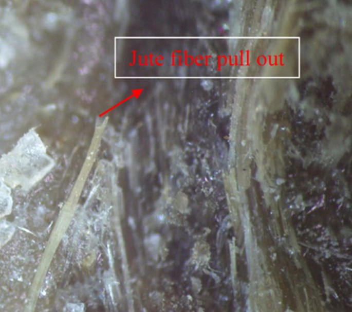
Front cross-sectional view
-
The Fig. 14 shows delamination in fractured samples.
Fig. 14 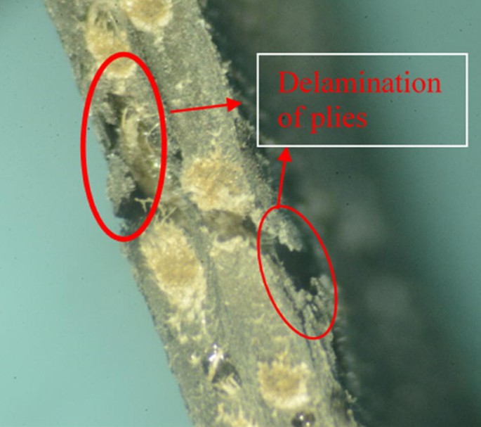
Side view of fractured specimen


Furthermore, Scanning Electron Microscope (SEM) images of CJCJC sequence reveals that matrix fails in form of matrix fragmentation. Voids can also be seen in Fig. 15a. Similar effect of voids are clearly highlighted in previous study [19,20,21,22] showing that these voids decrease tensile strength. It happened due to hand layup technique in which air is entrapped and relative movement of the fibers and resin during curing. Matrix/fiber fragmentation is found due to abrasion of the matrix from fiber fractured surfaces as shown in Fig. 15b. Fiber pull out is also encountered in Fig. 15c, d, which happens because of weak interfacial adhesion between matrix and fiber. Also, carbon fiber interacts well with epoxy (oxidizing agent) than jute fiber whose surface is not chemically active.

SEM images of CJCJC samples a voids presence, b matrix failure, c jute fiber pullout and d jute fiber showing more elongation
4 Conclusions
Following conclusions can be drawn from above study
-
Hybridization of carbon fiber with jute fiber can replace carbon fiber composites without significant loss in tensile strength.
-
Simulation technique that’s a nondestructive technique of material characterization has a good scope for predicting tensile response. 90% material cost can be saved which is required for tensile characterization through destructive lab experimentation. These simulations are widely used in aerospace and automotive industries.
-
Minimum deviation of simulation from average experimental results is 9% for CCJCC sequence and this error increases with increasing jute percentage due to non-uniform properties of jute.
-
Fractographic study shows that delamination phenomenon is present between plies and carbon fiber shows less pull-out than jute. Jute fiber reveals more elongation due to poor adhesion of jute fiber with epoxy resin.
-
SEM analysis depicted that matrix fails in form of fragmentation due to presence of voids and brittle nature of epoxy while fibers show pullout during failure.
References
Saiteja J, Jayakumar V, Bharathiraja G (2019) Evaluation of mechanical properties of jute fiber/carbon nano tube filler reinforced hybrid polymer composite. Mater Today Proc. https://doi.org/10.1016/j.matpr.2019.10.110
Ashworth S, Rongong J, Wilson P, Meredith J (2016) Mechanical and damping properties of resin transfer moulded jute-carbon hybrid composites. Compos B 105:60–66
Balakrishnan S, Krishnaraj C, Raajeshkrishna CR (2019) Mechanical characterization of pineapple, watermelon peel nanoparticles reinforced carbon, jute fabric, and its hybrid epoxy composites. Mater Res Express 6(10):105356
Raajeshkrishna CR, Chandramohan P, Saravanan D (2019) Effect of surface treatment and stacking sequence on mechanical properties of basalt/glass epoxy composites. Polym Polym Compos 27(4):201–214
Nirbhay M, Dixit A, Misra RK, Mali HS (2014) Tensile test simulation of CFRP Test specimen using finite elements. Procedia Mater Sci 5:267–273
Rafiquzzaman M, Islam M, Rahman H, Talukdar S, Hasan N (2016) Mechanical property evaluation of glass–jute fiber reinforced polymer composites. Polym Adv Technol 27(10):1308–1316
Gilioli A, Manes A, Giglio M (2018) Evaluation of the effects of the numerical modelling choices on the simulation of a tensile test on CFRP composite. Procedia Struct Integr 8:33–42
Wang HW, Zhou HW, Gui LL, Ji HW, Zhang XC (2014) Analysis of effect of fiber orientation on Young’s modulus for unidirectional fiber reinforced composites. Compos B Eng 56:733–739
Duleba B, Dulebová L, Spišák E (2014) Simulation and evaluation of carbon/epoxy composite systems using FEM and tensile test. Procedia Eng 96:70–74
Bandaru AK, Patel S, Sachan Y, Ahmad S, Alagirusamy R, Bhatnagar N (2016) Mechanical behavior of Kevlar/basalt reinforced polypropylene composites. Compos A Appl Sci Manuf 90:642–652
Vinšová L, Urban T (2017) Testing of mechanical properties of thick-walled carbon fiber composite for FEM simulations. Mater Today Proc 4(5):5989–5994
Ramana MV, Ramprasad S (2017) Experimental investigation on jute/carbon fibre reinforced epoxy based hybrid composites. Mater Today Proc 4(8):8654–8664
Glória GO et al (2017) Tensile strength of polyester composites reinforced with PALF. J Mater Res Technol 6(4):401–405
Hossain R, Islam A, Van Vuurea A, Verpoest I (2013) Tensile behavior of environment friendly jute epoxy laminated composite. Procedia Eng 56:782–788
de Oliveira CG, Margem FM, Monteiro SN, Lopes FPD (2017) Comparison between tensile behavior of epoxy and polyester matrix composites reinforced with eucalyptus fibers. J Mater Res Technol 6(4):406–410
Santulli C et al (2013) Mechanical behaviour of jute cloth/wool felts hybrid laminates. Mater Des 50:309–321
ASTM (2014) ASTM D3039/D3039M. Annual book of ASTM Standard, pp 1–13
Gay D, Hao SV, Tsai SW (2003) Ply properties. Compos Mater Des Appl 24:263–272
Naik RA (1995) Failure analysis of woven and braided fabric reinforced composites. J Compos Mater 29(17):2334–2363
Hernández S, Sket F, Molina-Aldareguía JM, González C, Lorca J (2011) Effect of curing cycle on void distribution and interlaminar shear strength in polymer-matrix composites. Compos Sci Technol 71(10):1331–1341
Dauda B, Oyadiji SO, Potluri P (2009) Characterising mechanical properties of braided and woven textile composite beams. Appl Compos Mater 16(1):15–31
Zhu H, Wu B, Li D, Zhang D, Chen Y (2011) Influence of voids on the tensile performance of carbon/epoxy fabric laminates. J Mater Sci Technol 27(1):69–73
Author information
Authors and Affiliations
Corresponding author
Ethics declarations
Conflict of interest
On behalf of all authors, the corresponding author states that there is no conflict of interest.
Additional information
Publisher's Note
Springer Nature remains neutral with regard to jurisdictional claims in published maps and institutional affiliations.
Rights and permissions
About this article

Cite this article
Khalid, M.Y., Nasir, M.A., Ali, A. et al. Experimental and numerical characterization of tensile property of jute/carbon fabric reinforced epoxy hybrid composites. SN Appl. Sci. 2, 577 (2020). https://doi.org/10.1007/s42452-020-2403-2
Received:
Accepted:
Published:
DOI: https://doi.org/10.1007/s42452-020-2403-2