
Abstract
A unique design for an optimized N-bit multiplier is proposed and implemented which utilizes a modified divide-and-conquer technique. The conventional technique requires four N/2-bit multipliers to perform N-bit multiplication, whereas the proposed design uses only one multiplier module in hardware to perform the functionality of four modules. It uses Dadda algorithm in its multiplier module. It has been implemented using Verilog HDL, and a good accuracy of results was observed in simulations which effectively verify its functionality. Design was also synthesized on various FPGAs including Spartan 3E, Virtex-5 and Virtex-7. Performance summary, after place and route, showed that the proposed approach significantly reduces hardware utilization. Furthermore, the proposed design is almost 75% more efficient in terms of resources utilization and operating frequency as compared to the conventional design.
1 Introduction
Multiplication is the most common, critical and widely used operation in many applications. The commonly used architectures include Baugh-Wooley and Booth multiplier. For multiplication of signed numbers, typically the Baugh-Wooley multiplier is preferred [1]. Radix-2 and Radix-4 booth multipliers were implemented in [2] for 8-bit and 16-bit multiplication. It was claimed that Radix-4 booth multiplier utilizes less resources and achieves high speed. Vedic algorithm can be used to handle complex mathematical problems and logic design [3], and it is a fast and low-power algorithm [4]. It solves numerous mathematical problems in 16 distinct ways. Researchers have also utilized Urdhva-Tiryakbhyam and Nikhilam multiplication algorithms. The former is a high-speed algorithm as the partial products are generated and added concurrently [5] while the latter one is more efficient in terms of hardware utilization [6]. An array multiplier is the simplest architecture but its drawback is its higher number of partial products as compared to the tree multipliers and hence it consumes more resources and time [7]. Wallace tree is also an advanced, pipelined, fast and highly used algorithm [8]. Xilinx also provides some tools to optimize the area, delay and power of the designed system. These tools have been realized in [9] on Dadda, Booth, Array and Wallace multipliers. They exhibited different properties in balanced, area-optimized, timing performance and power-optimized modes.
In [10], a re-configurable digit-serial multiplier is proposed which used clock gating for power optimization but this work does not optimize the resource consumption of FPGA. A two-dimensional bypassing technique is used in [11] to design the multiplier, and the article focused on optimization of power consumption and delay, whereas the proposed approach presented in this article optimizes the resource consumption of FPGA. In [12], a multiplexer-based 8-bit multiplier is presented with 50 MHz frequency, whereas the proposed architecture achieves 320 MHz frequency for 16-bit multiplication. E. George Walters III presents array multipliers using six-input LUTs and shift register LUTs [13], whereas the research presented in this article presents those using four-input LUTs. The modern FPGAs have built-in multipliers in them but still the configurable multipliers using LUTs play a vital role in many applications due to their flexible size, placement and modification ability [13]. Many researchers have worked on the design of multipliers earlier, as reported in this section, but they have not explored the option of reusing the same resources using iterative methods. Some of the advanced digital signal processing (DSP) applications demand more resources. The significance of the proposed work lies in its ability to reuse its multiplier module for multiple iterations. Therefore, by reducing the resources for the multiplication process, this work allows the designer to dedicate more resources for other modules in complex applications.
It can be concluded from literature review that Dadda algorithm is the most efficient in speed [14], while array multiplier shows the longest delay. Moreover, a brief comparison of Dadda and Wallace tree multipliers, as presented in [15], concluded that the Dadda multiplier is better in terms of speed and complexity than the Wallace tree multiplier. Dadda algorithm for tree reduction is usually used for reducing the propagation delay in the addition process of partial products.
Dadda algorithm can be used for 16-bit or higher order multiplication but with the increase in number of bits, the complexity also increases. For a 4-bit Dadda multiplier, the maximum tree height of partial products is four and reduction stages are three [16]. When the same algorithm is utilized to perform 8-bit multiplication, the tree height increases to six and reduction stages increase to four [17], thereby increasing the resources consumption and delay. To address this issue, a hybrid technique is developed in this article to perform 16-bit multiplication that uses 8-bit Dadda multiplier and divide-and-conquer technique.
2 Multiplication technique
Divide-and-conquer algorithm allows to perform multiplication process by dividing an N-bit number into two N/2-bit numbers. It executes series of multiplications and then performs the addition of partial products (PP) [18].

Divide-and-conquer methodology (16-bit number)
Referring to Fig. 1, we have two 16-bit numbers A and B which are expressed as:
Where \(A_{\rm H}\) and \(B_{\rm H}\) are the most significant half bits of each number, \(A_{\rm L}\) and \(B_{\rm L}\) are the least significant half, while \(k=2^{n/2}\) [18]. If the value of k is \(2^{1},\) then it represents single-bit left shift. Therefore, if we have 16-bit number, then \(2^{8}\) would represent a left shift of eight bits. The product of both numbers can be expressed as:
Multiplication will be performed using 8 bits from each number in a single iteration. The partial products (PP) can be written as:
The partial products (PP) are comprised of 16 bits. These partial products are further divided into two equal parts as:
Partial products are added after proper alignment to get the final product (FP) as per the following equations:
However, multiple adders are utilized to execute Eqs. (9–11) and the carry of each stage is added to the next stage. Details of the adder block are available in the later section. Similar concept can be used for higher bits.
3 Proposed optimized design
Conventionally, four multiplication processes of divide-and-conquer technique are implemented using four dedicated N/2-bit multipliers. It performs all multiplication processes at a time. Inputs at all four modules arrive at a time, and they produce partial products, respectively. A good optimization approach is to reuse the allocated resources on proper time intervals instead of dedicating each block of the design to only one iteration.
We propose a novel design to achieve N-bit multiplier using only one N/2-bit multiplier module. This concept is demonstrated for 16-bit multiplication using only one 8-bit multiplier module. It is a combination of divide-and-conquer mechanism and Dadda algorithm. The architecture and design of the proposed approach are given in Fig. 2.
A 2-bit counter is used to drive multiplexer (MUX) and decoder. Outputs of the multiplexers are attached to the inputs of multiplier. To produce four partial products, an 8-bit Dadda multiplier is used. Its outputs are stored in data registers, which are getting enable signal from the output of decoder. A finite state machine (FSM), as shown in Fig. 3, describes the complete cycle of iterations of the proposed design approach. This FSM shows that one partial product is produced in each state which is stored on only two data registers that are getting an active high signal from the decoder. The addition of products is similar to conventional approach. Detailed description is given in the following sections.
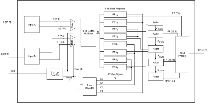
Architecture and design of 16-bit multiplier module

FSM of 16-bit multiplier module
3.1 Counter
A 2-bit up counter is used in this design to synchronize the multiplier inputs with respective storage registers. It resets its value to zero on reaching overflow state. The outputs of counter are connected to the MUX select lines as well as the decoder inputs.
3.2 Multiplexers
As in the proposed approach, there is only one multiplier module to produce four partial products. Therefore, the multiplier does not take the input values directly; it rather utilizes the multiplexers to generate partial products using four iterations. The inputs A and B are attached to the multiplexers as shown in Fig 2.
In this way, the inputs to multiplier will change according to the change in select lines of both multiplexers. Multiplexers will change their outputs according to Table 1.
3.3 Decoder
A 2–4 decoder provides enable signals to all data registers. Each of its output lines is connected to two registers. The MSBs and LSBs of multiplier output are stored in these registers separately. Although the output data are available to all eight data registers, the ones with high enable lines store the data. The decoder provides enable signals to the registers according to Table 2.
3.4 Multiplier module
The 8-bit Dadda multiplier performs four multiplication operations to produce \({\rm PP}_{1}\), \({\rm PP}_{2}\), \({\rm PP}_{3}\) and \({\rm PP}_{4}\) according to Eqs. 4–7. Dadda algorithm is usually used for reducing the propagation delay in the addition process of the partial products. The finite state machine of the proposed multiplication sequence is shown in Fig. 3 which uses the counter’s output sequence to generate partial products.
3.5 Adders
The addition of the partial products was accomplished by utilizing ripple carry adder since it is an area-efficient and less complex technique [19, 20]. Multiple adders have been used to carry out the addition of partial products to get the final product according to Eqs. (8–11). In single iteration, the adder can take only two inputs. Therefore, the addition process is further divided into multiple steps and the proposed design utilizes five 8-bit adders as shown in Fig. 2.
4 Results and comparison
The verification of the proposed algorithm was done by using multiple simulation environments. The design has been implemented using Verilog HDL and tested against various sets of inputs for multiplication. A good agreement between theoretical and simulation results was observed. The design was also implemented on various FPGAs including Spartan 3E (xc3s500-5fg320), Virtex-7 (xc7vx485t-3 ffg1157) and Virtex-5(xc5vlx20t-2ff323) to compare the resource utilization. The design is fully synthesizable, and estimation of all the resources was obtained after successful place and route process. Table 3 summarizes the resource utilization to verify the improved performance of the proposed design.
To demonstrate the fact that the improved results are due to the proposed architecture instead of the tools and technology, the design has been compared to the relevant literature which utilized the same technology and tools as used in this work. The proposed design was compared with [7] and [4], and the comparison results are tabulated in Table 4. The proposed design requires approximately 70% fewer resources (including flip-flops, LUTs and slice registers) as compared with [7] and [4] to produce the same multiplication. The reduction in LUTs is 73%, 74%, 77% and 81% as compared to the conventional approaches which utilized array, Dadda, Wallace and Vedic algorithms, respectively. Reduction in resources is due to the utilization of 75% less 8-bit multiplier modules as compared to the conventional technique. One module of an 8-bit Dadda multiplier requires seven half adders and 49 full adders. Each half adder contains five universal gates, and each full adder contains nine universal gates. The proposed work reduces three 8-bit multipliers. The implementation of three 8-bit multipliers require approximately 1428 gates. The additional components used to implement this approach are two multiplexers, one counter and one decoder which require approximately 4, 20 and 6 gates, respectively. Overall the proposed design reduces the gate count by almost 1400 gates. It also achieves 75% more operating frequency. Therefore, we conclude that the proposed design is more resource efficient than the conventional approach.
As the proposed design produces only one partial product at a time, it needs more iterations to perform complete multiplication process but it uses less resources. Consequently, there is a trade-off between resource consumption and number of iterations. Nevertheless, the proposed architecture has been designed with good optimization techniques which achieves high frequency leading to very quick process of iterations. Hence, this design not only reduces the resource utilization but is also fast as compared to the previous designs.
5 Conclusion
This article has presented a novel approach to design a multiplier by modifying the divide-and-conquer algorithm and optimizing it for resource utilization. For multiplication process, it uses Dadda algorithm. The design reduces the hardware multiplier modules from four to one, and therefore, it uses three times less resources as compared to the conventional approach. The proposed design can be operated at a higher frequency as compared to previous designs, which also makes it suitable for high-speed applications. It has been tested on various FPGAs to validate the results.
References
Badawi A, Alqarni A, Aljuffri A, BenSaleh MS, Obeid AM, Qasim SM (2015) FPGA realization and performance evaluation of fixed-width modified Baugh–Wooley multiplier. In: 2015 Third international conference on technological advances in electrical, electronics and computer engineering (TAEECE). IEEE, pp 55–158
Sukowati AI, Putra HD, Wibowo EP (2016) Usage area and speed performance analysis of booth multiplier on its FPGA implementation. In: International conference on informatics and computing (ICIC). IEEE, pp 117–121
Narula U, Tripathi R, Wakhle G (2015) High speed 16-bit digital vedic multiplier using FPGA. In: 2015 2nd international conference on computing for sustainable global development (INDIACom). IEEE, pp 121–124
Ram GC, Lakshmanna YR, Rani DS, Sindhuri KB (2016) Area efficient modified vedic multiplier. In: 2016 international conference on circuit, power and computing technologies (ICCPCT). IEEE, pp 1–5
Kumar KS, Swathi M (2018) 128-bit multiplier with low-area high-speed adder based on vedic mathematics. In: Proceedings of 2nd international conference on micro-electronics, electromagnetics and telecommunications. Springer, pp 163–172
Patil HP, Sawant S (2015) Design and implementation of energy efficient vedic multiplier using FPGA. In: 2015 International conference on information processing (ICIP). IEEE, pp 206–210
Ram GC, Rani DS, Balasaikesava R, Sindhuri KB (2016) Design of delay efficient modified 16 bit Wallace multiplier. In: IEEE International conference on recent trends in electronics, information & communication technology (RTEICT). IEEE, pp 1887–1891
Martha P, Kajal N, Kumari P, Rahul R (2018) An efficient way of implementing high speed 4-bit advanced multipliers in FPGA. In: 2018 2nd international conference on electronics, materials engineering & nano-technology (IEMENTech). IEEE, pp 1–5
Swee KLS, Hiung LH (2012) Performance comparison review of 32-bit multiplier designs. In: 2012 4th International conference on Intelligent and advanced systems (ICIAS), vol 2. IEEE, pp 836–841
Elsayed E, El-Boghdadi HM (2015) A novel power-efficient multi-operand digit-multiplier using reconfiguration and clock gating. J Supercomput 71:2539–2564
Srinivas KB, Aneesh YM (2014) Low power and high speed row and column bypass multiplier. In: 2014 IEEE international conference on computational intelligence and computing research, pp 1–4
Rashidi B, Sayedi SM, Farashahi RR (2014) Design of a low-power and low-cost booth-shift/add multiplexer-based multiplier. In: 2014 22nd Iranian conference on electrical engineering (ICEE), pp 14–19
Walters EG (2016) Array multipliers for high throughput in xilinx FPGAs with 6-input LUTs. Computers 5(4)
Buddhe V, Palsodkar P, Palsodakar P (2014) Design and verification of dadda algorithm based binary floating point multiplier. In: 2014 International conference on communications and signal processing (ICCSP). IEEE, pp 1073–1077
Townsend WJ, Swartzlander Jr. EE, Abraham JA A comparison of dadda and wallace multiplier delays. In: Optical science and technology, SPIE’s 48th Annual Meeting. International Society for Optics and Photonics, pp 552–560
Riaz MH, Ahmed SA, Javaid Q, Kamal T (2018) Low power 4 x 4 bit multiplier design using dadda algorithm and optimized full adder. In: 2018 15th international Bhurban conference on applied sciences and technology (IBCAST), pp 392–396
Jeevan B, Narender S, Reddy CK, Sivani K (2013) A high speed binary floating point multiplier using dadda algorithm. In: 2013 International multi-conference on automation, computing, communication, control and compressed sensing (iMac4s). IEEE, pp 455–460
Manolopoulos K, Reisis D, Chouliaras VA (2011) An efficient multiple precision floating-point multiplier. In: 2011 18th IEEE international conference on electronics, circuits and systems (ICECS). IEEE, pp 153–156
Shinde KD, Badiger S (2015) Analysis and comparative study of 8-bit adder for embedded application. In: 2015 International conference on control, instrumentation, communication and computational technologies (ICCICCT). IEEE, pp 279–283
Saini J, Agarwal S, Kansal A (2015) Performance, analysis and comparison of digital adders. In: 2015 International conference on advances in computer engineering and applications (ICACEA). IEEE, pp 80–83
Author information
Authors and Affiliations
Corresponding author
Ethics declarations
Conflict of interest
The authors declare that they have no conflict of interest.
Additional information
Publisher's Note
Springer Nature remains neutral with regard to jurisdictional claims in published maps and institutional affiliations.
Rights and permissions
About this article

Cite this article
Abrar, M., Elahi, H., Ahmad, B.A. et al. An area-optimized N-bit multiplication technique using N/2-bit multiplication algorithm. SN Appl. Sci. 1, 1348 (2019). https://doi.org/10.1007/s42452-019-1367-6
Received:
Accepted:
Published:
DOI: https://doi.org/10.1007/s42452-019-1367-6