
Abstract
According to the 2016 Mckinsey report, the global construction industry is one of the least productive (The Construction Productivity Imperative, McKinsey Report, 2016), which can be attributed to a minimal implementation of digital and automation technology (Berger Digtization in the Construction industry—Building Europe's road to "Construction 4.0 THINK/ACT—BEYOND MAINSTREAM, 2015). This research argues that this relates to the skill base of construction workers since very few, if any, can operate digital fabrication systems. Here, a digital model is considered foundational knowledge and is used to communicate with a fabrication unit. The difficulty lies in communicating the digital model to the fabrication machine, which arguably requires a level of specialist knowledge. However, history shows that other methods of communicating complex construction information have existed, such as 1:1 on-site drawing, which used to be made by architects or construction workers to communicate complex information related to constructing jigs or building components (The Tracing Floor of York Minster.” In Studies in the History of Civil Engineering, 1:81–86. The Engineering of Medieval Cathedrals. Routledge, 1997). We propose an alternative where we learn from history and amalgamate that knowledge with a robotic framework. We present the calibration process behind a parametric visual feedback method for robotic fabrication that detects on-object hand-drawn markings and allows us to assign digital information to detected markings. The technique is demonstrated through a 1:2 prototype that is fabricated using an ABB IRB 120 robot arm.
1 Preface
This paper presents ongoing research intending to develop new robotic interfacing methods for an existing mobile robotic framework (Kahlen 2020), as part of an industrial Ph.D. study undertaken at Aarhus School of Architecture in collaboration with Odico Construction Robotics. We will describe the calibration and implementation strategy for a parametric visual feedback method that was developed for a robotic fabrication workflow, where a tablet user interface controls fabrication tasks based on On-Object Hand-Drawn Markings(OOHDM) (Pedersen et al. 2020). The paper introduces current challenges and state-of-the-art of visual feedback systems in architectural research (Sect. 2.2), and architectural context (Sect. 2.1). Section 3 describes the implementation of computer vision (CV) techniques and how they are calibrated. Section 4 illustrates a case study that uses the developed method to fabricate a medium scale timber structure (2*2*0.6 m (W*H*D)). Last, the paper describes a system augmentation to enable detection of OOHDM’s on multiple surfaces of a given material (Sect. 5) and concludes by discussing the findings from previous sections (Sect. 6).
2 Introduction
Conventionally, digital fabrication, as an architectural fabrication technique, is an off-site technology exploited for its capabilities to create complex geometrical forms through infinitely varied pieces. Projects such as the Centre Pompidou Mets (Stehling et al. 2014) or the Opus Dubai (Opus Dubai 2020) are a result of such a process, where the fabrication technology was either Computer Numerically Controlled (CNC) machines or robots. Despite using different fabrication technologies, the starting condition is the same—a complex digital model, made by specialists and used to communicate with the fabrication facility. However, researchers and practitioners have begun to mature digital fabrication technologies for on-site work, for example, ETH’s ‘In Situ Fabricator’ (despite challenges related to positioning in space) (Giftthaler et al. December (2017)). Similarly, the ‘Factory on the Fly’ by Odico construction robotics (Kahlen 2020) (research subject for this Ph.D. project)—a mobile robot framework that is operated via a tablet device containing the digital model necessary to communicate fabrication information with a robot. While these approaches demonstrate potential solutions for automating on-site work, two issues remain: (1) construction workers still need to communicate with robot technologies and (2) robots are born with mechanical limitations, which can manifest as large limitations for a construction system. For instance, when designing a robot system for a given fabrication task, it is common to place the precision with the robot. Therefore, the robot setup needs to reach the length and width of the biggest workpiece for a specific task, which consequently requires a large, often costly robot, or a smaller robot coupled with a linear track. Regardless of which option is chosen, the robot system becomes larger and less mobile. But what if precision is placed with the human operator? He/she could physically mark where cuts or details would be positioned, and the robot would carry out the fabrication action. This scenario simplifies station design because the only requirement is to position the workpiece in front of the robot freely. Besides, the robot would need to be able to sense or see its work environment.
Computer Vision (CV), a branch of computer science, presents the opportunity of deducing meaning from a camera system, thereby making it possible to give ‘eyes’ to digital fabrication systems. The difficulty lies in interpreting the ‘seen’ signs/markings/symbols presented by humans. We argue that embedding digital systems with a visual system would make robotic interface methods intuitive for construction workers.
Consequently, this paper describes the calibration and implementation method for an existing visual robotic fabrication workflow (Pedersen et al. 2020) that allows users to interface with the robotic fabrication system through OOHDMs—i.e. a robot can be instructed through physical drawings/markings made on the material it processes. We describe the calibration steps, discuss the benefits of the method through the learning outcome of a 1:2 prototype, and present a system augmentation where drawings can be situated on multiple sides of a material. The work has been carried out using an inexpensive webcam from Logitech—model C920, an ABB IRB120 industrial robot arm equipped with a Kress mill, and the Emgu computer vision library (Emgu 2020).
2.1 Related historical work
Making drawings on-site to communicate construction information has a long history exemplified by the tracing floors of York Minster (ca 1350–1500). Here, architects/builders had a designated plaster floor made on-site into which they etched 1:1 drawings for complex jigs or architectural components (The Tracing Floor of York Minster 1997) (Fig. 1). This process resulted in formally complex buildings for their time, but the construction processes would take generations. By comparison, the pace of construction today has increased dramatically due to the hegemony of technology (digital fabrication and CAD drawings) that has enabled to shift many processes from on-site to off-site work. However, through personal building inspections, it has been found that hand-drawn symbols are used to communicate construction information today (Fig. 1). Therefore, one might argue that hand-drawn markings are still an integral part of on-site construction work. With this in mind, the research positions itself within this architectural tradition, a tradition where construction information is communicating through drawings; the shift occurs when communication is now between craftsmen and robot(s).

Left: Tracing of drawing floor in the York Minster by AR Whitaker (The Tracing Floor of York Minster 1997). Right: Photo from an on-site inspection of in progress timber house
2.2 Visual feedback state of the art
Today, there exist multitudes of visual feedback systems (a term used for any digital fabrication system that relies on sensor or camera technologies to enable an understanding of the physical world) for robotic fabrication. Many such systems have the common aim of increasing the accuracy by giving it a level of agency—whereby it adjusts future or current actions on some sensor feedback. Volker et al. (2016) present a method to mitigate propagating tolerances that result from material or hardware tolerances in a robotic system. Here, a digital model is updated based on information measured by a laser sensor. The updates inform subsequent robotic actions for physical assembly and fabrication (Volker et al. 2016). Sutjipto et al. (2018) use computer vision algorithms paired with a camera (integrated into a 3D printed tool) mounted on the wrist of a robot to analyse the complex material parameter space of robotic 3D printing (Sutjipto et al. 2018). Alvarez et al. (2018) present a method using computer vision to locate where to position a sewn joint on a partially assembled timber structure. Once the position of the sewn joint is identified, the movement of the robot adjusts to the physical situation (Alvarez et al. 2018). Last, Wu and Killian (2019) present a different visual system, where a robot learns through a Convolutional Neural Net (CNN) algorithm to position timber in different design configurations. As part of this system, Wu and Killian present two layers of visual feedback: (1) to understand the piece it is handling and (2) to understand the design it is making (Wu and Kilian 2019). The first three examples present methods aimed at solving workflows for geometrically complex architectures and are efficient in closed digital processes—i.e., the robot can reach every point in the full- or part of the assembly. Although this presents solutions to a niche problem, the approach has three downsides; it increases the complexity of using the system; it is highly specialized and solves one problem. Third, it limits the possibilities of the robotic system to small-scale work due to reachability. However, the last example (Wu and Killian 2019) presents a different opportunity—one where the robot understands/sees its physical reality.
This research builds upon the trajectory of the cyber-physical system with visual feedback, towards a process where a digital signal (image) is parsed for a physical input (drawing) and decipher meaning from it (fabrication information).
3 Visual feedback system
The developed cyber-physical system is outlined in Fig. 2, where this paper details the highlighted area related to calibration and implementation sequence. First, a brief outline of physical marking to the fabrication pipeline is described (Sect. 3.1). The choice of CV algorithms (Sect. 3.2) plays an essential role in the calibration steps of camera and algorithm (Sect. 3.3). The calibration process and choice of CV algorithm was developed through an idealized setup where hand drawings were made on paper, detected, and re-traced using an ABB IRB 120 robot. Later in the paper, system robustness is tested and documented in Sect. 4. The method is applied to a case study representing a less than ideal scenario (OOHDM’s on timber).

The paper describes the highlighted area of a developed workflow, where the focus is on elements associated with the process of detecting on-object hand-drawn markings
3.1 Robot path planning
The calibration process was prototyped in the CAD environment Rhinocerous3d and Grasshopper3d, where it was possible to build a pipeline that emulates a tablet user interface. Therefore, the grasshopper definition was controlled through a series of boolean toggles (native Grasshopper component) that instantiated various parts of the workflow (see numbered list). For instance, these actions can be used to add fabrication information, such as tool path offsets and milling depths, to the geometrical output (the base) from the computer vision algorithms. Actions include the following:
-
1.
move the robot to detection pose;
-
2.
get geometrical information from drawing (base);
-
3.
add lap joint information to the base;
-
4.
the base is a cut-out;
-
5.
the base is a cut;
-
6.
the base is a trim operation, and
-
7.
fabricate
For instance, if toggle two is pressed, we get the CAD representation of the physical drawing that serves as the base for subsequent actions. Following this action, toggle three is pressed, and the base is used as the basis for a set of rules whereby it is converted to a lap joint (currently works for straight lines). The resulting geometry has a rapid program assigned to it through an in-house robotic fabrication grasshopper plugin that allows to execute rapid code directly on the robot by pressing toggle 7 (granted it has PCSDK (ABB-Developer Center 2019) enabled). Since this method was only used to develop the calibration process, it is deemed ok that it does not follow safety regulations.
3.2 Computer vsion
The visual feedback system uses CV algorithms compiled in EmguCV (2020), a C#DotNet wrapper of OpenCV. During the development, two CV methods to digitize hand-drawn markings in a video stream were identified—HoughLinesP (OpenCV: Hough Line Transform 2020) and Image Contour(OpenCV: Contours : Getting Started 2020) (Fig. 3). The accuracy of both algorithms is increased when using binary images, which is made using methods such as “Canny edge detection” (Canny 1986) or “inRange” (OpenCV: Thresholding Operations Using InRange 2020) functions from the Emgu library.

Top: test carried out using the HoughLineP function that produces scattered line segments, needing a geometrical clean up to produce a relevant output. Bottom: show how the ImageContour function produces a continuous result with no need of post processing
The preferred method is “image contour” as it produces clear outlines for curves, lines, and closed curves (Fig. 3, bottom). However, each type needs a separate method for deriving the central axis that is the basis for creating robotic fabrication information (Fig. 4).

a Centreline for a line is made using a variation of a principal component analysis (PCA) (Pearson November 1901). b Closed curves are represented in pairs (inside and outside of the curve), where the central curve is found by averaging point pairs on both curves. c The centre line for curves is calculated using a medial axis algorithm (Felkel and Obdrzalek 1998)
3.3 Calibration process
The following paragraphs describe the sequence of steps that allows integrating the visual feedback method with a robot. The calibration method was developed by equipping an ABB IR120 arm with a 3D-printed tool carrying a pen and an inexpensive web-camera. The aim was to detect and re-trace a drawing made by the robot operator on a piece of paper.
Pen calibration and auto-detections of the drawing position The simplest way to isolate a drawing in an image is to know its colour. Therefore, the first calibration step is to identify the colour spectrum of a marker for a given lighting condition. Knowing the colour spectrum of the marker makes it simple to isolate markings/drawings made with it in an image/video stream with the inRange function (OpenCV: Thresholding Operations Using InRange 2020). However, if the lighting conditions change drastically, it will be necessary to recalibrate this step. However, if the robot system is positioned in a near-constant lighting situation, this might be avoided.
This research tested multiple markers and found that a red or blue was best suited for the robot context. Isolating the marker colour allows to automatically isolate the drawing and generate a Rectangle of Interest (ROI). The ROI is of crucial importance as it speeds up the computational process and minimizes/removes noise from the CV output since algorithms are only applied within the ROI (Fig. 5, bottom).

The markers are calibrated by placing sample points in the regions of the sample drawing, which returns a min/max value for an RGB spectrum for that marker. This colour spectrum is then used to isolate the drawing and find its location in pixel space
Camera Calibration All images have spherical distortion due to the focal length of the camera, which took the photo. This distortion can be removed using methods found in Emgu (Camera Calibration With OpenCV–OpenCV Documentation 2019) and require a camera- and distortion matrix. These are computed once by analysing several images (15 +) that include a checkerboard printout. Once the matrices are calculated, they are applied to each image taken with that camera. Figure 6 shows the variation from no calibration to a good one (A good calibration has a deviation value close to 0.). The retraced robot drawing (blue) drifts with no- and poor calibration compared to a good calibration. This research used a calibration with a deviation factor of 0.11(Fig. 6, right), and the retracing is within 1 mm of the centreline of the drawing.

Three different scenarios of camera calibration, where a bad calibration makes the detected drawings drift when re-traced with the robot (middle images)
Calibrating scale/orientation and identifying work-object position in pixel-space The values and positions found in the images are in pixel space and needs to be converted to metric space and positioned digitally in front of the robot. The scale factor is computed once, unless the detection pose changes (Fig. 2), using a printout with several lines of known size and different orientation. The lines are found using the CV techniques described in Sect. 3.2. When found, each line has its central axis computed and scaled to the known size, returning one scale factor pr line. All scale factors are summarized and averaged to produce one unified scale factor. When the single scale factor is applied to all lines, it returns lines with a deviation from the known length at − 0.64 to + 0.66 mm, a deviation which is deemed satisfactory (Fig. 7, top).

a (Left) The calibration print out is placed in front of the robot. a (Right) showing the derived centre lines, individual and averaged scale factor alongside the deviations from the lengths in the printout. b (Left) The calibration print out is placed in front of the robot. b (Right) The detected lines and their angles with world X or Y. b The work-object position in the image
Next, the rotation relative to the robot is identified. Similarly, identifying the scale factor, a printout with two lines is aligned and positioned in the work area. The lines signify X/Y direction, and when detected, the centreline representation can be used to compute the angle with a digital world X/Y axis (Fig. 7, bottom).
Last, the position of the calibrated robot work-object (description of the surface that the robot is working on and is typically calibrated using a routine on the robot.) in pixel space is identified (Fig. 7, bottom). Knowing this allows the robot to perform its fabrication routine in the right position through the following steps:
-
After centreline extraction, scale, and rotation, subtract detected objects XY components with the XY components of the identified pixel-space work object
-
These positions detected objects with respect to 0,0 in a world coordinate system
-
Before fabrication reorient detected objects using the calibrated robot work-object
-
Generate fabrication code and fabricate
4 Adoption of system to case study
Once the calibration process was developed, it was tested against a case study designed to document following subjects:
-
system robustness;
-
precision of the system, and
-
benefits of the method with respect to on-site robotic processes.
The case study explores the fabrication of a 1:2 scale timber frame structure constructed from roughly sawn timber (A material with visual noise, in the form of grain/knot structure and rough texture.). The basis for the structure is a hand-drawn sketch and OOHDMs are used for robot programming (Fig. 8, top). OOHDMs can be either closed/open curves or lines that can make simple cuts or be digitally augmented with joinery details (Fig. 8, bottom).

Top: From file to fabrication. Notice how the robot accurately mill the marking. Bottom: how the on-object markings are used to communicate various fabrication information
As was earlier stated, the case-study was carried out using an ABB IRB 120 robot arm equipped with a camera and Kress mill with a 6-mm routing bit (Fig. 8, right). The robot processes 600–1700 mm long linear elements in both ends, which is far beyond the described reach of the robot (IRB—Industrial Robots (Robotics)—Industrial Robots From ABB Robotics 2020).
The case study was carried out using the same setup as the calibration process, but with a different tool and camera position. Therefore, the scale and rotation had to be re-calibrated. The calibration printouts are positioned on top of the workpiece in the cutting area, and the routine described in Sect. 3.2 is carried out. Calibrating on top of the workpiece is necessary since this is where the OOHDMs are made and, therefore, where the scale needs to be identified. Once performed, the autodetection method was tested and returned good results (Fig. 9).

The calibration steps and test of the calibration setup
After recalibrating the system—two frames as pr, the sketch in Fig. 8 was constructed and is shown in Fig. 10. The fabrication was carried out by the researcher, who is adept at using robots and has some carpentry skill.

The final piece, a 1:2 scale two framed timber structure with a bounding volume of 2 by 2.1 by 0.6 m, where individual timber pieces are between 0.6 to 1.7 m in length. The markings to the top left and bottom right show where there were experienced inaccuracies in the structure—not because of the machining process, but simply due to false positions made by the operator
4.1 Case-study findings
Carrying out the case study was an immense learning experience, revealing that the accuracy varies depending on which curve type had been drawn (line or curve). There is a simple explanation for this—variation in the method used to convert the outlines from Emgu to a centreline representation. Therefore, this highlights an area to improve, as the accuracy for lines is within a millimetre, but for curves, it is 2–3 mm. The aim is to do more research in computer graphics to find better methods for centreline creation. The case study found minor system inaccuracies, but the structure’s assembly revealed that some OOHDMs had been wrongly positioned by the operator, leading to tolerances of ± 15 mm. These were not due to system issues because the robot always machined the workpiece where there was a drawing/marking (Fig. 10, bottom right). However, they were quickly adopted by altering subsequent OOHDMs. Therefore, an argument could be made that the method is accurate, with inaccuracies of 2–3 mm in worst cases and within a millimeter at best.
Another discovery was issues related to computing the scale factor. Within the current setup, the scale needs recomputing every time the cross-section of the material changes. If we assume the camera/image stream is flat (see Sect. 3.2) and positioned at a fixed Z-position, the scale factor should vary linearly depending on the workpiece cross-section. This indicates that computing the new scale factor can be automated through a micro-controller and sensor that communicates the camera’s measurement to the top of the workpiece to the server (Fig. 2).
The method presented through the paper solves many issues related to on-site robotics, where we wish to highlight the following:
-
Reachability issues—the method negates reach issues since the workpiece can be freely positioned within the cut zone with an OOHDM visible to the system. Therefore, smaller cheaper robots can be used to process elements far longer than the robot reach (Fig. 11, bottom)
Fig. 11 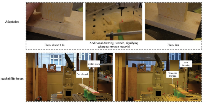
Top: Adaptation—if pieces do not fit, one can simple redraw on a piece and use that information to remove extra material. Bottom: Reach—the reach of the robot becomes negligible because the workpiece and OOHDM can be positioned freely within the cutting area
-
On-Site adjustments—it is known that using digital fabrication technologies can lead to accumulating tolerances due to various factors (Volker et al. 2016). Therefore, it is seen as an asset that the method allows to adjust already cut pieces, without any need of digital modelling or complex workflow development (Fig. 11, top)
-
Native communication method—the process uses a communication method that is simple and native to construction workers—the drawing. Therefore, it is assumed that it would make the system more accessible for on-site work as it does not require re-education of the workforce. However, this has not been tested yet, and is, therefore, a claim made by the researcher, but later research will aim to document if this is true

In addition to the findings, the case study uncovered the following work to be carried out as the system continues to mature:
-
Develop a flexible method for identifying drawing scale using a micro-controller and laser sensor.
-
Make better curve centre line generation to increase precision.
-
Implement a machine learning strategy for
-
Identification of drawing location. The current method takes 1–2 s and could be sped up in this way
-
Develop a human to robot language, to allow user to communicate what type of robotic action is needed through numbers or symbols.
-
Store drawing information to optimize work processes for making copies of duplicate objects.
-
Use the drawing information to automatically build a digital model to keep track of the construction process.
5 System augmentation
Disclaimer: This area of research was carried out during the Covid-19 pandemic, where the research team was not able to make use of any robots. Therefore, it is a digital study that is validated through the success of the method documented through Sects. 3, 4.
After concluding the case-study, it was realized that the method was limited to 2D detection of OOHDMs, and. Therefore. has a limited design space (Fig. 12, top). Contrary to digital fabrication’s strength, that is the infinitely varied (Fig. 12, bottom). Therefore, we propose a system augmentation where multiple cameras are used to detect OOHDMs on several sides of a workpiece. This new process is developed through a digital case-study, where numerous photos have been taken around a piece of timber, using the methods described through Sects. 3, 4, 5.1 and 5.2. The system augmentation describes the potential changes to hardware (Sect. 5.1) and how detected objects from multiple sides are combined to a 3D model (Sect. 5.2).

5.1 Hardware updates to the system
Currently, the setup makes use of a single camera mounted on the robot arm in a 3d-printed mount (Fig. 13, top left), which is moved to a predefined pose, where the camera can see the work area and pieces to cut. This pose will be referred to as the “Master pose” because it serves as the basis for assembling drawings detected on other sides of the workpiece (Sect. 5.2). The developed setup could continue to be used; the robot would navigate to all the different detection positions. However, this positions the robot in awkward positions (Fig. 13, top middle), which might not be reachable or able to give a perpendicular image as described in Fig. 13, bottom. These limitations could be mitigated through cleaver positioning of the work-area within the reach of the robot, or by using a larger robot with better reach. But, this goes against the described benefits of Sect. 4.1, hence why a second option is proposed. The second option takes its inspiration from WU and Kilian (2019), where fixed cameras were positioned around the work-area of complex aggregations made by a robot (Wu and Kilian 2019). It is proposed to amalgamate this idea with the current use of a “Master pose”, where OOHDM’s detected from the fixed cameras would be combined with the one(s) detected from the master pose (Fig. 13, top right). Using this method allows to not stray from the identified benefits of the method.

Top: To the left is the pose used in the current method, which is referred to as the “master pose”. The middle shows the different poses if the current approach is used. To the right multiple cameras are situated around the work area, OOHDMs detected at either camera will be combined with the one from the Master pose. Bottom: When detecting OOHDMs the images should be taken perpendicular to the side of the workpiece
5.2 Combining multiple detected OOHSM’s
Detecting drawings on multiple sides of a workpiece is challenging not because of hardware or the detection process (see Sects. 3 and 4); the challenge is how the detected drawings are combined into a 3D model that can be used for fabrication. This research has developed a method where OOHDMs detected at the master pose are used to position and combine any subsequent OOHDMs. All OOHDMs are detected using the developed techniques, meaning that each camera has a unique scale, rotation and work-object defined (Fig. 14). Making use of the developed technique allows to combine multiple OOHDMs through the following simple steps (Fig. 14 for info):

Describes the naming conventions used in Sect. 5.2, and (right) highlights how each image has the necessary information to perform a successful detection—i.e. calibrated work object, work-object identified in each image, etc.
-
Detect a drawing at the master pose.
-
Check if there are drawings elsewhere.
-
If a drawing is detected in views 1 or 2, use the robot work object positioning method described in Sect. 3.3.
-
This orients the digital twin correctly with respect to its own work-object, but it might not be positioned precisely in relation to the drawing from the master pose.
-
Depending on which detection camera was used, reposition the drawing from the component with the highest Z-coordinate to either the start or end of the master pose drawing.
-
If a drawing is detected in view 3, use the robot work object positioning method described Sect. 3.3.
-
Move the repositioned drawing by a factor known due to a fixed position of the work piece or the use of a micro controller that has measured the necessary information.
-
Depending on the combination of detected OOHDMS, use native Rhino/Grasshopper functions, such as sweep 1 or 2, to create a 3rd model.
5.3 Testing the method
The presented method was tested through a series of digital pre-studies, where a setup resembling Fig. 13 (top, middle) had been used to take a series of images with a workpiece. OOHDMs were then made digitally on top of the images and used to develop the assembly method. Once concluded, the method was tested against physical OOHDMs that yielded a sufficient 3D model ready to cut, see Fig. 15 for the results of the study.

Results from a digital pre-study aimed at developing the correlation method to combine multiple OOHDM’s to a 3rd model ready for fabrication
6 Conclusion
This paper has presented the calibration of a novel visual feedback method. It demonstrates its functionality through a fabrication process driven by on-object hand-drawn markings successfully negating the digital model as the starting condition of a digital fabrication process. The paper documented a calibration method in ideal conditions and is adapted to a far from ideal fabrication scenario. Here, the system was shown to cope with various visual noise types such as debris, construction materials or other visual noise. As a result, the calibration method and subsequent visual feedback method were successfully established and are now considered robust and well suited for on-site robotic processes in mobile robotic units.
Future work will be extended towards industrial applications in mobile robot units; new case studies; and trials with non-specialists as the technique matures with the described new developments. These new applications would better the understanding of the developed process and highlight limitations/potential related to human–machine interfacing in the construction industry, and how these are necessary to move forward.
References
Harvey JH (1997) “The Tracing Floor of York Minster.” In: Studies in the History of Civil Engineering, vol 1, pp 81–86. The Engineering of Medieval Cathedrals. Routledge, 1997
Mckinsey (2016) Reinventing Construction: a route to higher productivity. https://www.mckinsey.com/business-functions/operations/our-insights/reinventing-construction-through-a-productivity-revolution. Accessed 11 Jun 2020
(2016) Berger, Roland: Digtization in the Construction industry - Building Europe's road to "Construction 4.0 THINK / ACT – BEYOND MAINSTREAM, 2015 June 2016
(2020) “Opus Dubai.” Accessed June 11, 2020. https://odico.dk/en/references/opus-dubai-2
(2020) “Emgu CV: OpenCV in .NET (C#, VB, C++ and More).” Accessed January 20, 2020. http://www.emgu.com/wiki/index.php/Main_Page
ABB-Developer Center. Accessed July 8, 2019. http://developercenter.robotstudio.com/pcsdk
Alvarez ME, Erik EM-P, Ehsan B, Oliver DK, Tobias S, Lauren V, Chai H, Achim M, Philip FY (2019) Tailored Structures, Robotic Sewing of Wooden Shells. In: Jan W, Philippe B, Marco H, Kendra B, Tim S (eds) Robotic Fabrication in Architecture, Art and Design 2018, 405–20. Springer International Publishing, New York
Bullar J (2013) Complete Guide to Joint-Making, The. GMC Publications, Lewes, East Sussex
Camera Calibration With OpenCV — OpenCV 2.4.13.7 Documentation. Accessed 12 Nov 2019. https://docs.opencv.org/2.4/doc/tutorials/calib3d/camera_calibration/camera_calibration.html
Canny J (1986) A Computational Approach to Edge Detection. In: Ieee Transactions on Pattern Analysis and Machine Intelligence
Felkel P, Obdrzalek S (eds) (1998) “Straight Skeleton Implementation”, 210–18. Comenius University, Bratislava
Giftthaler M, Sandy T, Dörfler K, Brooks I, Buckingham M, Rey G, Kohler M, Gramazio F, Buchli J (2017) Mobile robotic fabrication at 1:1 scale: the in situ fabricator. Constr Robots 1(1–4):3–14. https://doi.org/10.1007/s41693-017-0003-5
Hoadley RB (2000) Understanding Wood: A Craftsman’s Guide to Wood Technology. In: 2nd Revised edition edition. Newtown, CT : Emeryville, CA: Taunton Press Inc
“IRB 120 - Industrial Robots (Robotics) - Industrial Robots From ABB Robotics.” Accessed February 9, 2020. https://new.abb.com/products/robotics/industrial-robots/irb-120.
Kahlen J (2020) “Factory on the Fly.” Odico (blog). Accessed August 28, 2020. https://odico.dk/en/factoryonthefly/.
OpenCV: Hough Line Transform. Accessed 21 Jan 2020. https://docs.opencv.org/3.4/d3/de6/tutorial_js_houghlines.html
OpenCV: Contours : Getting Started. Accessed February 9, 2020. https://docs.opencv.org/3.4/d4/d73/tutorial_py_contours_begin.html
OpenCV: Thresholding Operations Using InRange. Accessed 21 Jan 2020. https://docs.opencv.org/3.4/da/d97/tutorial_threshold_inRange.html
Pearson K (1901) On lines and planes of closest fit to systems of points in space. LondEdinb Dublin Philos Mag J Sci 2(11):559–572. https://doi.org/10.1080/14786440109462720
Pedersen J, Narendrakrishnan N, Jay H, Asbjørn S, Dagmar R (2020) augmented drawn construction symbols: a method for ad hoc robotic fabrication. Int J ArchitComput. https://doi.org/10.1177/1478077120943163
Stehling H, Fabian S, Jean R, Fabio G, Matthias K, Silke L (2014) Bridging the gap from cad to cam:: concepts, caveats and a new grasshopper plug-in. In: Fabricate 2014, DGO-Digital original., 52–59. Negotiating Design & Making. UCL Press, 2017. https://doi.org/10.2307/j.ctt1tp3c5w.10
Sutjipto S, Daniel T, Gavin P, Teresa V-C, Tim S (2019) Towards Visual Feedback Loops for Robot-Controlled Additive Manufacturing. In: Jan W, Philippe B, Marco H, Kendra B, Tim S (eds) Robotic Fabrication in Architecture, Art and Design 2018, 85–97. Springer International Publishing
Volker H, Michael K, Thomas Fabio G, Matthias K (2016) Additive robotic fabrication of complex timber structures. In: Advancing wood architecture: a computational approach, 1st ed., 29–43. Routledge, London; New York
Wu K, Kilian A (2019) Designing Natural Wood Log Structures with Stochastic Assembly and Deep Learning. In: Jan W, Philippe B, Marco H, Kendra B, Tim S (eds) Robotic fabrication in architecture, art and design 2018, pp 16–30. Springer International Publishing
Zwerger K (2015) Wood and Wood Joints. 3rd ed. edition. Basel ; Boston: Birkhäuser
Funding
The research is partly funded by the Danish Innovation fund.
Author information
Authors and Affiliations
Corresponding author
Additional information
Publisher's Note
Springer Nature remains neutral with regard to jurisdictional claims in published maps and institutional affiliations.
Rights and permissions
About this article

Cite this article
Pedersen, J., Søndergaard, A. & Reinhardt, D. Hand-drawn digital fabrication: calibrating a visual communication method for robotic on-site fabrication. Constr Robot 5, 159–173 (2021). https://doi.org/10.1007/s41693-020-00049-2
Received:
Accepted:
Published:
Issue Date:
DOI: https://doi.org/10.1007/s41693-020-00049-2